The Smell of Molten Projects in the Morning

Ed Nisley's Blog: Shop notes, electronics, firmware, machinery, 3D printing, laser cuttery, and curiosities. Contents: 100% human thinking, 0% AI slop.

Category: Science

If you measure something often enough, it becomes science

  • Glass Tiles: USB Charger Current Waveforms

    Glass Tiles: USB Charger Current Waveforms

    Looking at what comes out of various USB chargers, with the Tek current probe monitoring the juice:

    USB Current-Probe Extender - in action
    USB Current-Probe Extender – in action

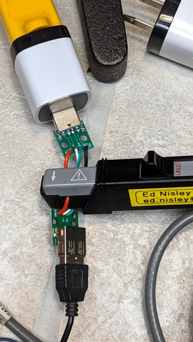
    First, a known-good bench supply set to 5.0 V:

    Tiles 2x2 - bench supply - 50 mA-div
    Tiles 2×2 – bench supply – 50 mA-div

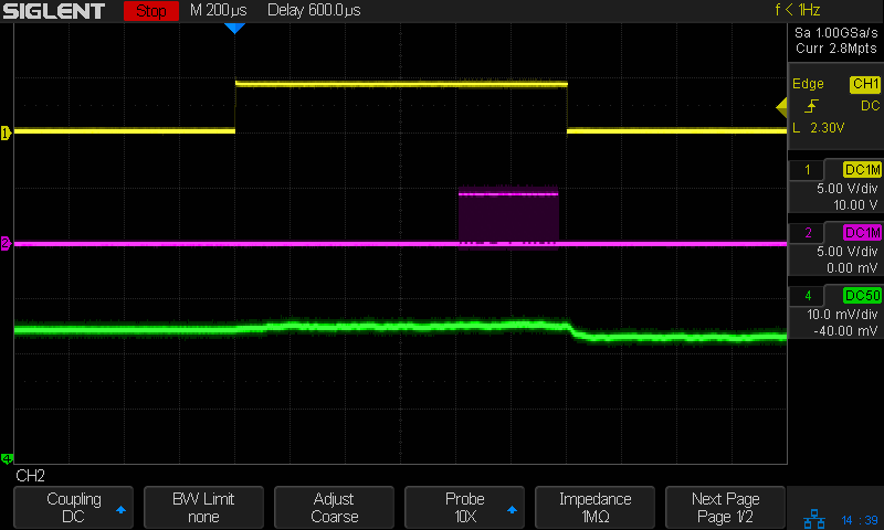
    The yellow trace is the Glass Tile Heartbeat output, which goes high during the active part of the loop. The purple trace shows the serial data going to the SK6812 RGBW LEDs. The green trace is the USB current at 50 mA/div, with the Glass Tile LED array + Arduino drawing somewhere between 50 and 100 mA; most of that goes to the LEDs.

    The current steps downward by about 10 mA just after the data stream ends, because that’s where the LEDs latch their new PWM values. The code is changing a single LED from one color to another, so the current will increase or decrease by the difference of the two currents.

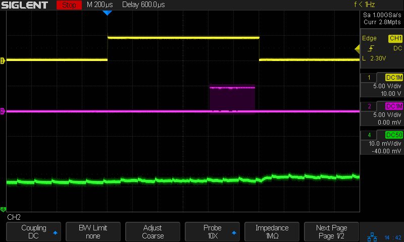
    A charger from my Google Pixel 3a phone (actually made by Flextronics and, uniquely, UL listed), with Google’s ever-so-trendy and completely unreadable medium gray lettering on a light gray plastic body:

    Google Pixel charger - dataplate
    Google Pixel charger – dataplate

    The current waveform looks only slightly choppy:

    Tiles 2x2 - Google Flextronics charger - 50 mA-div
    Tiles 2×2 – Google Flextronics charger – 50 mA-div

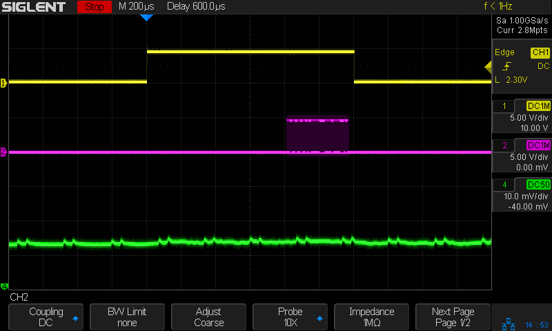
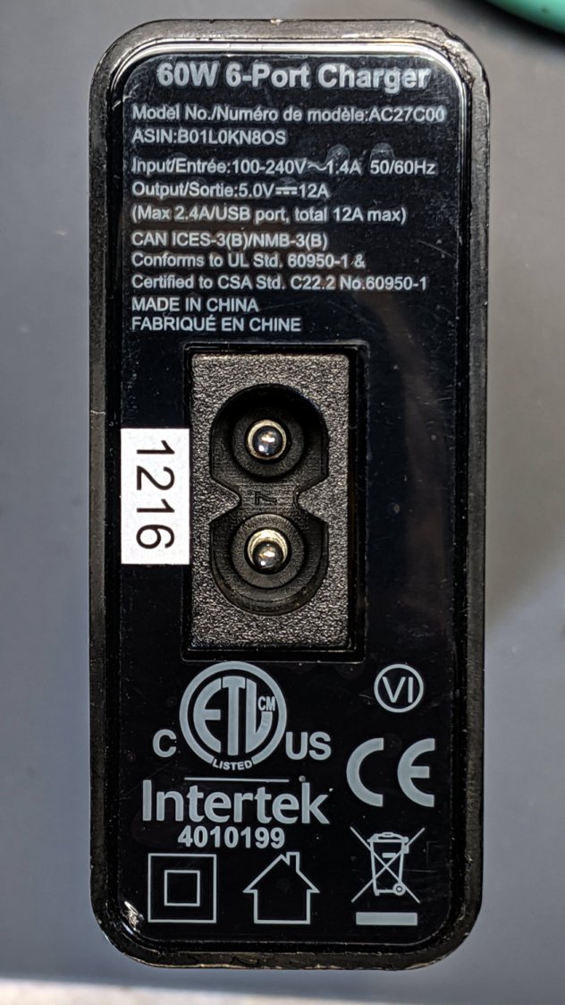
    An AmazonBasics six-port USB charger from tested by Intertek:

    AmazonBasics charger - dataplate
    AmazonBasics charger – dataplate

    The waveform:

    Tiles 2x2 - Amazon Basics Intertek Basics charger - 50 mA-div
    Tiles 2×2 – Amazon Basics Intertek Basics charger – 50 mA-div

    A blackweb (their lack of capitalization) charger, also made tested by Intertek:

    blackweb charger - dataplate
    blackweb charger – dataplate

    The current:

    Tiles 2x2 - blackweb charger - 50 mA-div
    Tiles 2×2 – blackweb charger – 50 mA-div

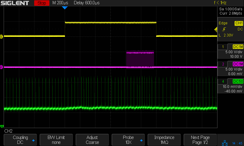
    Finally, one from a lot of dirt-cheap chargers from eBay:

    Anonymous white charger - dataplate
    Anonymous white charger – dataplate

    Which has the most interesting current waveform of all:

    Tiles 2x2 - anon white charger - 50 mA-div
    Tiles 2×2 – anon white charger – 50 mA-div

    A closer look:

    Tiles 2x2 - anon white charger - pulse detail - 50 mA-div
    Tiles 2×2 – anon white charger – pulse detail – 50 mA-div

    From the 75 mA baseline, the charger is ramming 175 mA pulses at 24 kHz into the filter cap on the Arduino Nano PCB! The green trace has a few seconds of (digital) persistence, so you’re seeing a lot of frequency jitter; the pulses most likely come from a voltage comparator controlling the charger’s PWM cycle.

    It’s about what one should expect for $1.28 apiece, right?

    They’re down to $1.19 today: who knows what the waveform might be?

    Update: Having gotten a clue from a comment posted instantly after I fat-fingered the schedule for this post, I now know Intertek is a testing agency, not a manufacturer.

  • USB Testers vs. Reality

    USB Testers vs. Reality

    Set up a test harness with a USB tester between two amputated USB cables:

    USB Testers - Keweisi plugged
    USB Testers – Keweisi plugged

    Input comes from a bench power supply:

    USB Testers - 5 V input clips
    USB Testers – 5 V input clips

    Output goes to an 8 Ω power resistor:

    USB Testers - 8 ohm load
    USB Testers – 8 ohm load

    Yes, it’s mounted on the isothermal block from back in the Thing-O-Matic days, disspating barely 2 W. Thermocouples FTW, but in this case I don’t care about the temperature.

    Because these are random USB cables, they come with the usual caveats. Indeed, I measured a 9.8 Ω loop resistance (!) at the input end. The resistor is slightly under 8Ω, so the 1.8 Ω wire resistance suggests (at least) one of the USB cables contains very little copper. That’s measured without the USB tester in series, because it tries really hard to power up from the ohmmeter’s source voltage and basically shorts out the resistor.

    Both testers accurately report the source voltage with no load, so I presume the voltage shown with current flowing through the resistor represents the actual voltage at the tester. The source cable drops a substantial voltage under load.

    The 8 Ω resistor should draw 5 V / 8 Ω = 625 mA at 5 V. The voltmeter probes provide a non-intrusive way to measure the actual current by working backwards: current = volts / 8 Ω. As it turned out, the resistor sees less than 4 V with the bench supply set to 5.0 V.

    So, we begin.

    With the bench supply at 5.5 V, the Keweisi meter shows 4.9 V and 0.48 A with 4.0 V across the resistor for an actual 500 mA current. The source cable drops 600 mV, indicating a wire resistance of 1.2 Ω, about 2/3 of the total wire resistance.

    The anonymous meter produces two different results for an actual 500 mA current, depending on nothing under my control:

    • Supply 5.3 V, indicated 5.0 V and 0.5 A
    • Supply 5.1 V, indicated 4.76 V and 0.5 A

    Both results show about 300 mV source drop, half of the Keweisi meter’s 600 mV, suggesting a wire resistance of 0.6 Ω. The meter displays a blinking ▲, presumably indicating the input voltage is kinda high.

    I have no explanation.

    After the meters measured an actual 500 mA load for about an hour:

    • Keweisi: 1.6 hr → 782 mA·h, should be 800 mA·h
    • Anonymous: 1.0 hr → 515 mA·h, should be 500 mA·h

    Which roughly agrees with the battery charge data:

    USB Testers - Charge vs Runtime
    USB Testers – Charge vs Runtime

    The anonymous meter seems reasonably accurate, the Keweisi meter undershoots by 2.5%, and they’re both Close Enough for simple measurements.

    There’s probably a duty cycle effect, too, because the battery charger presents a pulsed load, but I’m just not going to worry about it.

  • Robin Nest: Eggs!

    Robin Nest: Eggs!

    After pausing to recover from construction, Ms Robin laid four eggs in four days:

    • Garage Robin Nest - first egg - 2020-05-28
    • Garage Robin Nest - 2 eggs - 2020-05-29
    • Garage Robin Nest - 3 eggs - 2020-05-30
    • Garage Robin Nest - 4 eggs - 2020-05-31

    She’s surprisingly tolerant of our comings and goings, as well as garage door openings and closings:

    Garage Robin Nest - robin brooding
    Garage Robin Nest – robin brooding

    We’re trying to stay out of her way as much as possible.

    The gallery pix come from my phone, held against the soffit over the nest, and aimed entirely by feel, while standing on the Greater Ladder. If I had access to the top of the soffit, I’d drill a webcam hole, but …

  • Monthly Science: USB Current Testers vs. NP-BX1 Batteries

    Monthly Science: USB Current Testers vs. NP-BX1 Batteries

    Having some interest in my Sony HDR-AS30 helmet camera’s NP-BX1 battery runtime, I’ve been measuring and plotting recharge versus runtime after each ride:

    USB Testers - Charge vs Runtime
    USB Testers – Charge vs Runtime

    The vertical axis is the total charge in mA·h, the horizontal axis is the discharge time = recorded video duration. Because 1 A = 1 coulomb/s, 1 mA·h = 3.6 C.

    The data points fall neatly on two lines corresponding to a pair of cheap USB testers:

    USB Testers
    USB Testers

    When you have one tester, you know the USB current. When you have two testers, you’re … uncertain.

    The upper tester is completely anonymous, helpfully displaying USB Tester while starting up. The lower one is labeled “Keweisi” to distinguish it from the myriad others on eBay with identical hardware; its display doesn’t provide any identifying information.

    The back sides reveal the current sense resistors:

    USB Testers - sense resistors
    USB Testers – sense resistors

    Even the 25 mΩ resistor drops enough voltage that the charger’s blue LED dims appreciably during each current pulse. The 50 mΩ resistor seems somewhat worse in that regard, but eyeballs are notoriously uncalibrated optical sensors.

    The upper line (from the anonymous tester) has a slope of 11.8 mA·h/minute of discharge time, the lower (from the Keweisi tester) works out to 8.5 mA·h/minute. There’s no way to reconcile the difference, so at some point I should measure the actual current and compare it with their displays.

    Earlier testing suggested the camera uses 2.2 W = 600 mA at 3.7 V. Each minute of runtime consumes 10 mA·h of charge:

    10 mA·h = 600 mA × 60 s / (3600 s/hour)

    Which is in pretty good agreement with neither of the testers, but at least it’s in the right ballpark. If you boldly average the two slopes, it’s dead on at 10.1 mA·h/min; numerology can produce any answer you need if you try hard enough.

    Actually, I’d believe the anonymous meter’s results are closer to the truth, because recharging a lithium battery requires 10% to 20% more energy than the battery delivered to the device, so 11.8 mA·h/min sounds about right.

    Memo to Self: Trust, but verify.

  • Beaver Dam: More Timber!

    Beaver Dam: More Timber!

    Team Beaver continues to add logs, branches, and mud to their dam beside the Dutchess Rail Trail:

    Beaver Lodge and Dam - DCRT N of Golds Gym - 2020-05-26
    Beaver Lodge and Dam – DCRT N of Golds Gym – 2020-05-26

    Apparently they’re now busy raising a bunch of little beavers inside the lodge. Next year we expect the water will begin rising in other marshes along the rail trail.

    Go, beavers, go!

  • Snakeskin

    Snakeskin

    A shed snakeskin appeared when I opened the garage door:

    Snakeskin - overview
    Snakeskin – overview

    The skin sits atop the retaining wall next to the door, on a stone(-like) background with poor contrast: even an empty snake has good camouflage!

    The exterior looks like genuine snakeskin:

    Snakeskin - exterior
    Snakeskin – exterior

    I didn’t know the interior has an entirely different pattern:

    Snakeskin - interior
    Snakeskin – interior

    As far as I can tell, the snake was going about its business elsewhere in the yard.

    To be fair, there’s some luck involved.

    Update: After Mitch nudged me, I found the (somewhat the worse for wear) snakeskin again. The head end was split, much as I described, but the tail end was intact (the snake having pulled out like a finger from a glove) and what I though was the inside of the top was the outside of the bottom, just pushed inward to form a very thin double layer.

    Today I Learned … to always look closer!

  • Gosling Time

    Gosling Time

    The Dutchess Rail Trail has gotten far more use in recent months than ever before, with entire families walking along the path:

    Canada Geese Families on the Rail Trail - 2020-05-08
    Canada Geese Families on the Rail Trail – 2020-05-08

    Almost by definition, though, goslings don’t practice social distancing …