Ed Nisley's Blog: Shop notes, electronics, firmware, machinery, 3D printing, laser cuttery, and curiosities. Contents: 100% human thinking, 0% AI slop.
We used Diamond K540KM truck mirror-bracket antenna mounts clamped to the top seatback rail on our Tour Easy recumbents for several years, but they weren’t entirely satisfactory. The vibration from our ordinary on-road bike rides (a TE isn’t an off-road bike!) fractured the stamped-steel base after four years.
Antenna Bracket Repair
I fixed that by screwing a steel plate across the crack. It became obvious that these mounts weren’t suited to the application when the second mount failed shortly thereafter.
Broken Diamond K540KM Antenna Mount
But we kept using them and, as you might expect, Mary’s mount failed in the middle of a 350-mile bike ride when the die-cast support dingus broke. The fresh granular metal fracture looks dead white in the picture.
I lashed the pieces together with a multitude of cable ties and we completed the mission. When I rolled our bikes into the Basement Laboratory Bike Repair Wing after returning home, the mount on my bike failed.
These mounts aren’t intended for “high vibration” applications and, it seems, bicycles produce much higher vibration than trucks. I’m certain that the frequency range is higher, although I’m not sure about the amplitude.
Obviously, it was time for something better… which meant some quality shop time. More on that tomorrow.
Mary dropped a pair of her sunglasses that disintegrated on impact: both earpieces broke off. She has trouble finding sunglasses that fit, so this is not to be taken lightly…
The sunglasses had interchangeable lenses, a feature which she’d never used, and the lower of the two tabs that snapped into the earpieces had broken off — on both sides, simultaneously. These weren’t high-snoot items, but they were name-brand: Rudy Project from, IIRC, nashbar.com.
Peering through the microscope, it turns out that the lens material may have been pretty good optically, but wasn’t up to the mechanical task: the two remaining tabs had deep stress cracks. The right-side picture shows the lens upside-down, as that was the easiest way to set up the shot.
Notice the many, many cracks that penetrate nearly all the way through the tabs. The tabs didn’t break because she dropped the glasses on the floor, they broke because there was barely anything left holding the tabs in place.
Mind you, she’d never removed the lenses from the earpieces, so this isn’t a case of failure-from-overuse, either. They’re about a year old, more or less, and have been used in stressful tasks like gardening and the occasional bike ride.
Urethane adhesive foam-in-place
I slobbered urethane glue into the ends of the earpieces to mechanically lock the remaining tabs in place and fill all the voids. It looks rather ugly here, but the excess adhesive simply snaps off because it doesn’t chemically bond with either of the other two plastics.
Rudy sunglasses stress cracking – center
After screwing everything back together again, I noticed that there’s another stress crack growing in the middle of the lens, just over the nosepiece. These sunglasses are not long for this world: that failure will be an end-of-life event.
The frames claim “Designed in Italy” which doesn’t win any points with me; the design is fundamentally flawed.
Yo, Rudy, how about designing some sunglasses with a high-tech feature like durability… rather than style?
Oh, yeah, I suppose this repair voids the Warranty. Perhaps buying from Nashbar on sale triggers this clause: “Buying Rudy Project sunglasses, goggles or helmets from an online retailer at a price below the suggested retail price (MSRP) voids your warranty.” The expense of sending them in negates any possible benefit, which I’m sure they realize, too.
Our daughter has been helping a friend learn to ride a bike (at age 15: it’s never too late!) and we’ve been rehabilitating a new-to-her bike in the process. It’s an inexpensive Ross bike, perfect for the task at hand, and is providing a good introduction to machine-shop work.
The fact that it’s much older than she is makes not a whit of difference. Nay, verily, I rode a bike pretty much like this one for hundreds & hundreds of miles back in the day. I got better ones when I could afford them and she will, too; maybe we’ll tempt her into a recumbent bike some day…
Anyhow, the seat tended to spin around even with the clamp cranked dangerously tight. Taking a look down the tube showed that they used welded-seam tubing (it really was an inexpensive bike) and didn’t bother to clean up the internal seam. As a result, the chromed steel seat post rested on maybe three small patches of metal that didn’t provide much friction at all.
I wrapped a neodymium magnet in a rag and stuffed it down the tube to catch the filings, then applied a coarse cylindrical file (a rat-tail would work as well) to the seam. When it was nearly flush, I switched to a finer file to smooth it and the other high spots. The picture shows the improved seam, ready for the seat post. Ugly, but rough is actually a Good Thing in this situation.
Seat Clamp Swaging
The seat tube has a nominal 1-inch OD, so I clamped a random round from the heap in the vise, tapped the clamp around it, and massaged it lightly with a hammer to persuade it into a more cylindrical shape. It’s still not perfect, but at least the bolt lugs engage the seat tube around the slit somewhat better.
With all that in hand, the seat post is now perfectly secure.
On her first “I can ride!” parking-lot outing, she experimentally determined that a bicycle wheel’s lowest-energy state resembles the edge of a potato chip. Fortunately, it was the front wheel and, after a bit more shop derring-do than one might wish, we swapped in another wheel that’s been hanging on the garage wall for a decade, ready for just such an occasion.
Remember how independent your first bike made you feel? It’s working that way for those two, just like it did for us. Life is full of bumps and they’ll get hurt every now and then, but there’s no other way to get through it; they’re just about ready to ride over the horizon.
Happy Independence Day for those of us in the USA!
While replacing the rear derailleur on Mary’s Tour Easy, I rediscovered that I have two different cable sizes in my stash: large brake cables and small derailleur cables.
The large ferrules are 0.235 inches in diameter, the smaller 0.187 inches. The brazed-on cable-stop sockets are obviously sized for the larger ferrules, which makes perfect sense.
If you put a small ferrule in a large stop, it tends to cant whichever way the cable pulls it. That results in the cable sawing into the edge of the ferrule… and that results in excess friction and sometimes a broken cable.
In the past I’ve snipped out little brass shimstock rectangles, wrapped them around mandrels, and generally spent a lot of time fiddling around. This time I remembered to rummage in my collection of brass tubing cutoffs, which yielded a pair of very-nearly-perfect slip fit pieces that neatly adapted the small ferrules to the large stops.
Rear shift cable with modified ferrules
Life is good…
I have no idea what the cables look like on weight-weenie exotic-frame bikes. For sure, this isn’t a trick for hydraulic disk brakes.
Incidentally, the cable housing length worked out to 130 mm. Neither of the charts in the SRAM X.7 instructions matched the TE’s butt end; the seat stay angle is halfway between what’s normal for diamond-frame bikes. So we picked a reasonable length and it seems to be OK.
As I mentioned there, I originally connected my bicycle-mobile amateur radio gadget to the ICOM IC-Z1A radio using separate mic and speaker plugs. That seemed like a good idea, but bicycles vibrate a lot and the plugs apply enough leverage to the jacks inside the radio to pry them right off the PCB. That requires a protracted repair session that I never wanted to do again.
The solution is to mount both plugs rigidly on the radio so that they simply can’t move. I dithered for a while and finally decided that function trumps good looks on this project, particularly given that our radios spend their entire lives inside a bag behind the bike seats.
The top picture shows the small aluminum plates I made to align the plugs to the HT jacks, along with a plastic gluing fixture to hold the plugs parallel while the epoxy cures. If you just jam the plugs into the radio without an alignment fixture, you will glue the plugs together in such a way that they cannot be removed: the radio does not hold the shafts exactly parallel!
Plug stabilization – What Not To Do
How do I know? Well, I tried doing exactly that by simply epoxying the existing plugs into place, applying enough epoxy putty to stabilize the plugs against the radio. Looks reasonable, but when it came time to take them out (and you will want to take them out, trust me) they are firmly and permanently embedded. I had to carve them apart to get them out.
The mic, speaker, and coaxial power jacks are 10 mm on center. The 2.5 mm mic plug has a small shoulder that required a matching recess in the plate, while the 3.5 mm speaker plug is basically a cylinder. I don’t use the coaxial power jack, having hacked an alkaline battery pack with Anderson Powerpoles. The plate’s external contour matches the flat area atop the radio around the jacks.
You could lay out and drill close-enough holes by hand, use a step drill to make the shoulder recess, and then let the epoxy do the final alignment. However, you want the center-to-center distance exactly spot-on correct, as the plugs won’t mate properly otherwise. I turned it into a CNC project for my Sherline mill, of course, but that’s just because I have one.
HT Plugs in gluing fixture
This picture shows two plugs epoxied into the plate. While the epoxy cures, the plate rests atop the fixture with the two plugs vertical and their shell flanges flush against it. I applied the epoxy with a toothpick and worked it into the gap between the threads and the plate.
The end result will be a pair of plugs that exactly match the radio’s jacks in a plate that sits firmly atop the radio’s case. You should find that the plugs snap firmly into place and the entire assembly is absolutely rigid.
Caveat: don’t use an aluminum plate if your radio depends on separate electrical connections for the mic and speaker plug shells. The IC-Z1A has isolated shells, but remains happy when they’re connected. My Kenwood TH-F6A HT uses the shells for entirely different functions and will not work with them shorted together.
With the epoxy cured, wire the connections as usual. I had a small cable with enough tiny wires to put the mic conductors in their own shielded pair, but that’s likely overkill.
Finished plugs with epoxy blob
You could machine a nice enclosure, but I simply molded an epoxy putty turd around the connections, shells, and cable. The trick is to wait until it’s nearly cured, plug it into the radio, then shave off whatever gets in the way of the knobs, antenna plug, and other appurtenances.
The radio on Mary’s bike has been misbehaving over the last few months: the PTT button on the handlebars occasionally had no effect. Debugging this sort of intermittent problem is quite difficult, as it would sometimes fail and repair itself before we could get stopped in a safe place where I could poke around in the wiring.
After months of this nonsense, I narrowed the failure down to the short cable from the HT’s mic jack to the interface board: by positioning the cable just so, the radio would work fine for days or weeks at a time. I taped the thing in position and all was well, at least for a few days or weeks at a time.
These two pictures show what the interface looked like back in 2001 when I put it together (modified from another version I did in 1997!) and what it looks like today. The most significant change is in the plugs connecting the whole affair to the HT: a CNC-machined plate holds them perfectly parallel at the proper spacing and an epoxy-putty turd fuses them into a rigid mass. More on that sub-project tomorrow…
Loose plugs, it turns out, vibrate the HT’s jacks right off the circuit board in short order and those jacks are a major pain to replace. Ask me how I know…
The wire break seemed to be precisely where the mic cable exits the epoxy turd. You’d expect a fatigue fracture to occur at that spot, so I wasn’t particularly surprised, although I was amazed that the thing hadn’t failed completely over the months I spend fiddling with it. I finally resolved to fix this once and for all, which meant either flaying the cable and patching the wire in situ or rebuilding the whole connector assembly. Either choice requires enough fiddly work to discourage even me.
Sooo, disconnect everything & haul it to the Basement Laboratory, Electronics Workbench Division…
Before cutting into the cable, I measured the mic voltage on the PCB and tried to make the thing fail on the bench. The HT (an ancient ICOM IC-Z1A) normally presents 3.5 V DC on the mic wire and the external PTT switch pulls it to ground through a 22 kΩ (or 33 kΩ or thereabouts) resistor. The mic audio is a small AC signal riding a volt or so of DC bias with the PTT active.
The wire measured maybe 0.25 volts and the PTT dragged it flat dead to ground. Yup, through that honkin’ big resistor. Well, maybe the last conductor in that mic wire had finally broken, right there on the bench?
Measured from the 2.5 mm plug tip conductor (tip = mic, ring = 3.5 V DC, sleeve = mic common) to the PCB pad on the PC, the mic wire stubbornly read 0.0 Ω, regardless of any wiggling & jiggling I applied to the cable. But no voltage got through from the radio to the board…
Sticking a bare 2.5 mm plug into the HT mic jack produced a steady 3.5 V on the tip lug. Reinstalling my epoxy-turd plug assembly produced either 0.25 or 3.5 V, depending on whether I twisted the thing this way or that way.
Ah-ha! Gotcha!
Pulled out my lifetime supply of Caig DeoxIT Red, applied a minute drop to the end of the mic plug, rammed it home & yanked it out several times, wiped off the residue, and the PTT now works perfectly. Did the same thing to the adjacent speaker plug, just on general principles, and I suspect that’ll be all good, too.
Diagnosis: oxidation or accumulated crud on the mic jack inside the radio.
Now, to try it out on the bike and see how long this fix lasts. Anything will work fine on the bench, but very few things survive for long on a bicycle.
Memo to Self: It’s always the connectors. Unless it’s the wires.
Here’s the schematic, just in case you’re wondering. I wouldn’t do it this way today, but that’s because I’ve learned a bit over the last decade or so…
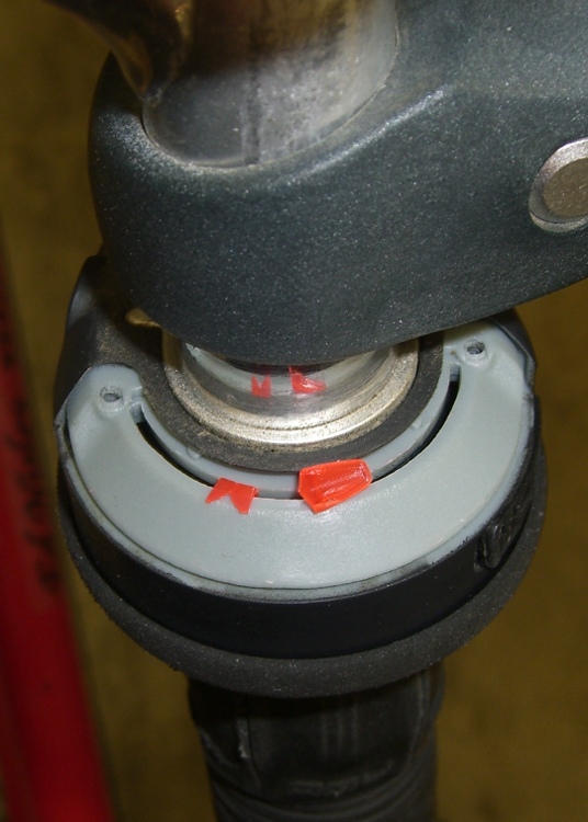
The little red pointer inside my Tour Easy’s rear SRAM Grip-Shift broke. Back in the old days, this wouldn’t be a problem, as we used friction shifters on the downtube (as we rode to school, uphill, in the snow, both ways) and knew by feel which gear was engaged. But that was then, this is now, and fixing things is what I do anyway.
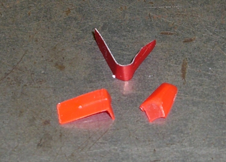
The pointer turned out to be a thin plastic strip, molded into an L with a domed arch over the pointy end. It simply rests in a slot in the shifter mechanism, held in place by the transparent cover (which, mercifully, came off without dismantling the bike or even removing the cable).
I made a similar replacement from thin red-anodized aluminum, but that didn’t work out at all. The mechanism snaps from one gear to the next at roughly the speed of heat, accelerating the pointer so rapidly that the aluminum deformed. Score one for plastic!
Actually, I made two aluminum pointers. Prototype One vanished into the Sargasso heap in front of the Solvents & Lubricants Shelves at the first upshift; that’s when I discovered just how much snap that shifter applies to the pointer. Made another one, installed the cover, and then discovered it wasn’t going to work.
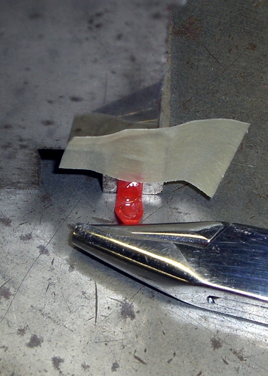
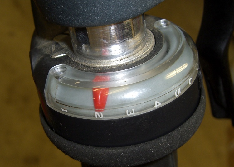
So I applied some Plastruct solvent adhesive to the broken plastic bits, lined the parts up on my crusty surface plate, applied a bit of gentle pressure overnight, and in the morning had a like-new pointer. It installed just fine and works like the original.
Solvent-bonded plastic is supposed to be just about as strong as the original material. We’ll see just how long this repair lasts…
Pop Quiz: Do you know the first four derivatives of position w.r.t. time?
Answer: Velocity, acceleration, jerk, and snap. You could look it up…
Update: Alas, the repair lasted only about two weeks before failing at the same spot. Some deep rummaging produced a similar (but more thoroughly dead) SRAM shifter. Turns out the pointers are similar, so I salvaged the older one. Ya gotta have stuff… and remember it, too, which is becoming something of a challenge.