Ed Nisley's Blog: Shop notes, electronics, firmware, machinery, 3D printing, laser cuttery, and curiosities. Contents: 100% human thinking, 0% AI slop.
I should mention the lamp test in case it comes in useful later on…
	digitalWrite(PIN_HEARTBEAT,LOW);	// turn off while panel blinks

	analogWrite(PIN_DIMMING,LEDS_ON);	// enable LED array

	for (byte i=0; i<NUMROWS; i++) {
		for (byte j=0; j<NUMCOLS; j++) {
			LEDs[i].ColR = LEDs[i].ColG = LEDs[i].ColB = 0x80 >> j;
			for (byte k=0; k<NUMROWS; k++) {
				UpdateLEDs(k);
				delay(25);
				if (GeigerTicked) {
					GeigerTicked = false;
					TogglePin(PIN_HEARTBEAT);
				}
			}
		LEDs[i].ColR = LEDs[i].ColG = LEDs[i].ColB = 0;
		}
	}
	UpdateLEDs(NUMROWS-1);			// clear the last LED
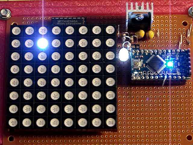
Updating / multiplexing all the rows inside the inner loop with a 25 ms pause produces distinct flashes and demonstrates that each LED operates separately from all the others:
Lamp Test
The lamp test ends with all the LEDs turned off, but having the array gradually fill with light looked odd.
After some tinkering, I added the GeigerTicked conditional to handshake with the Geiger pulse interrupt handler, thus producing a nice random time at the end of the loop. Feed that mostly random time into the hash function, use the hash as the random number seed, then set all the LEDs using random(2) function calls:
	randomSeed(jenkins_one_at_a_time_hash((char *)GeigerTime,4));

	for (byte Row=0; Row<NUMROWS; Row++) {
		for (byte Col=0; Col<NUMCOLS; Col++) {		// Col runs backwards, but we don't care
			LEDs[Row].ColR |= random(2) << Col;
			LEDs[Row].ColG |= random(2) << Col;
			LEDs[Row].ColB |= random(2) << Col;
		}
		UpdateLEDs(Row);
	}

	GeigerTicks = 0;				// reset counter
	GeigerTicked = false;			// resume capture
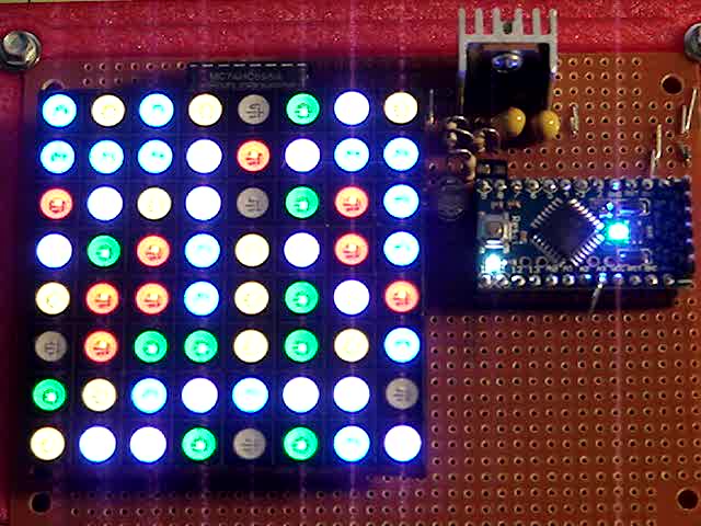
Which produced a more-or-less random fill that looked better:
Random Preload – bright
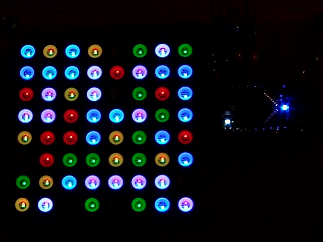
Underexposed to reduce the burnout (after a few Geiger events):
Random Preload – dim
There should be about eight of each color and, hey, it’s close enough.
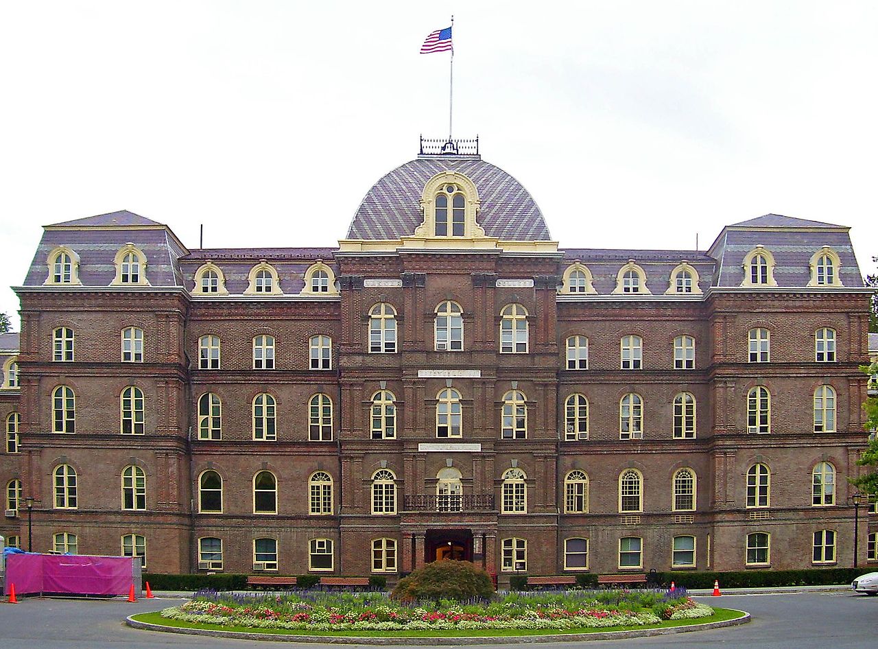
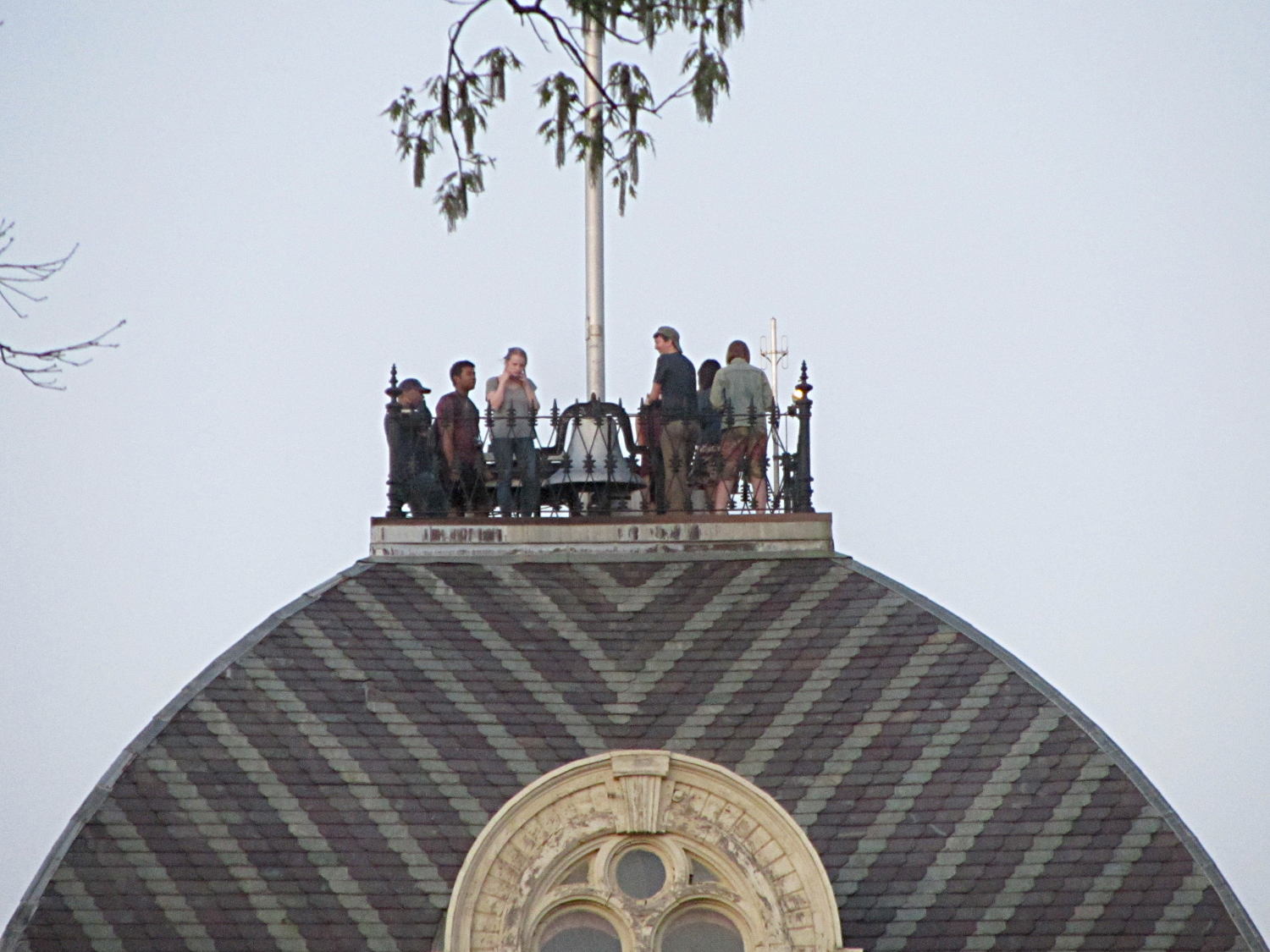
MHVLUG meetings end around 8 pm and, depending on this-and-that, the bell atop Old Main on the Vassar College campus will be tolling the hour as we emerge. Here’s a scene-setting photo from Wikimedia, taken from about where I parked the car:
Vassar College Old Main Building
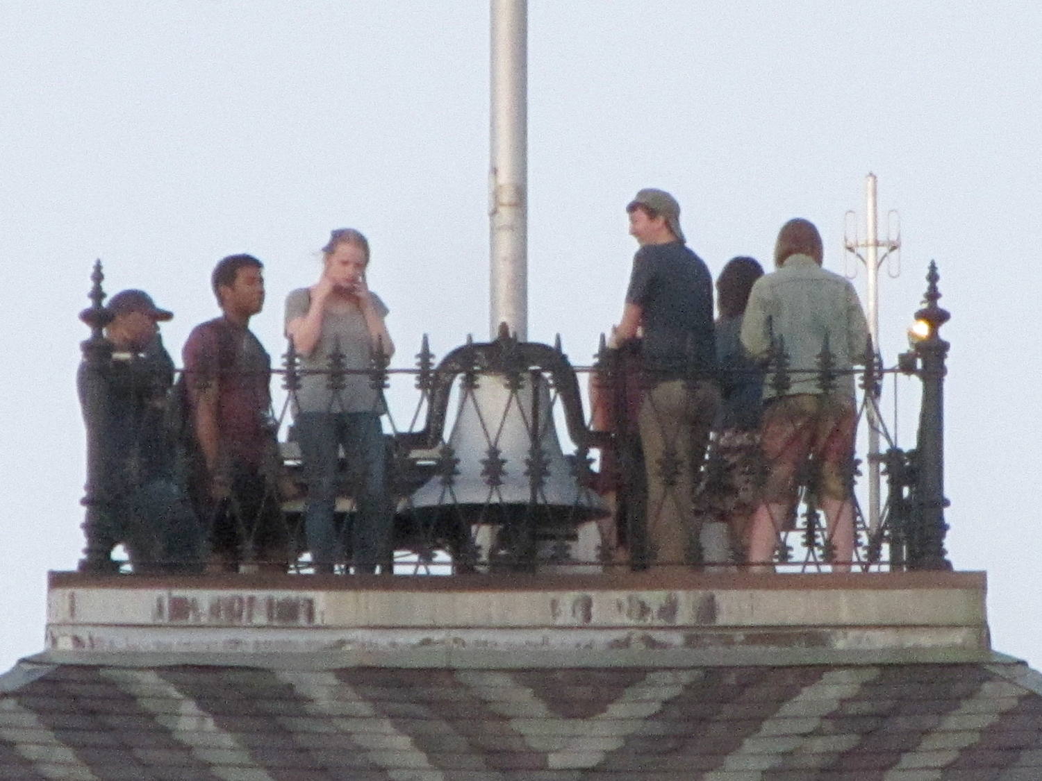
Although the bell didn’t have its usual steady rhythm after the most recent meeting, I didn’t expect this:
Bell Ringers atop Vassar Old Main
The tree grows in the near foreground, not over Old Main.
Two of them realized the risk of permanent hearing damage, but do you see the real hazard?
The “pen holder” in an HP 7475A plotter carries the pen across the width of the paper:
HP 7475A – Pen Holder – overview
Given that it was designed to carry pens, not knives, I wasn’t surprised that the spring-loaded finger clamping the knife adapter didn’t apply enough force to hold the adapter in place against the cutting forces. I figured a quick test of a gizmo to stabilize the adapter would be in order, even though I knew:
The pen holder doesn’t apply enough downward force
The knife adapter doesn’t have a depth-of-cut shroud around the blade
In order to build the gizmo, I need the carrier’s dimensions…
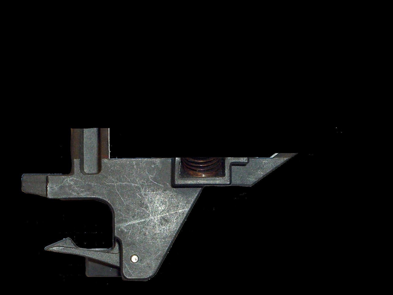
An overhead photo of the pen holder shows the layout in the XY plane:
HP7475A – pen holder – top view
I shouldn’t have used graph paper as a background, because the next step was to remove the background and isolate the carrier:
HP7475A – pen holder – top view – isolated
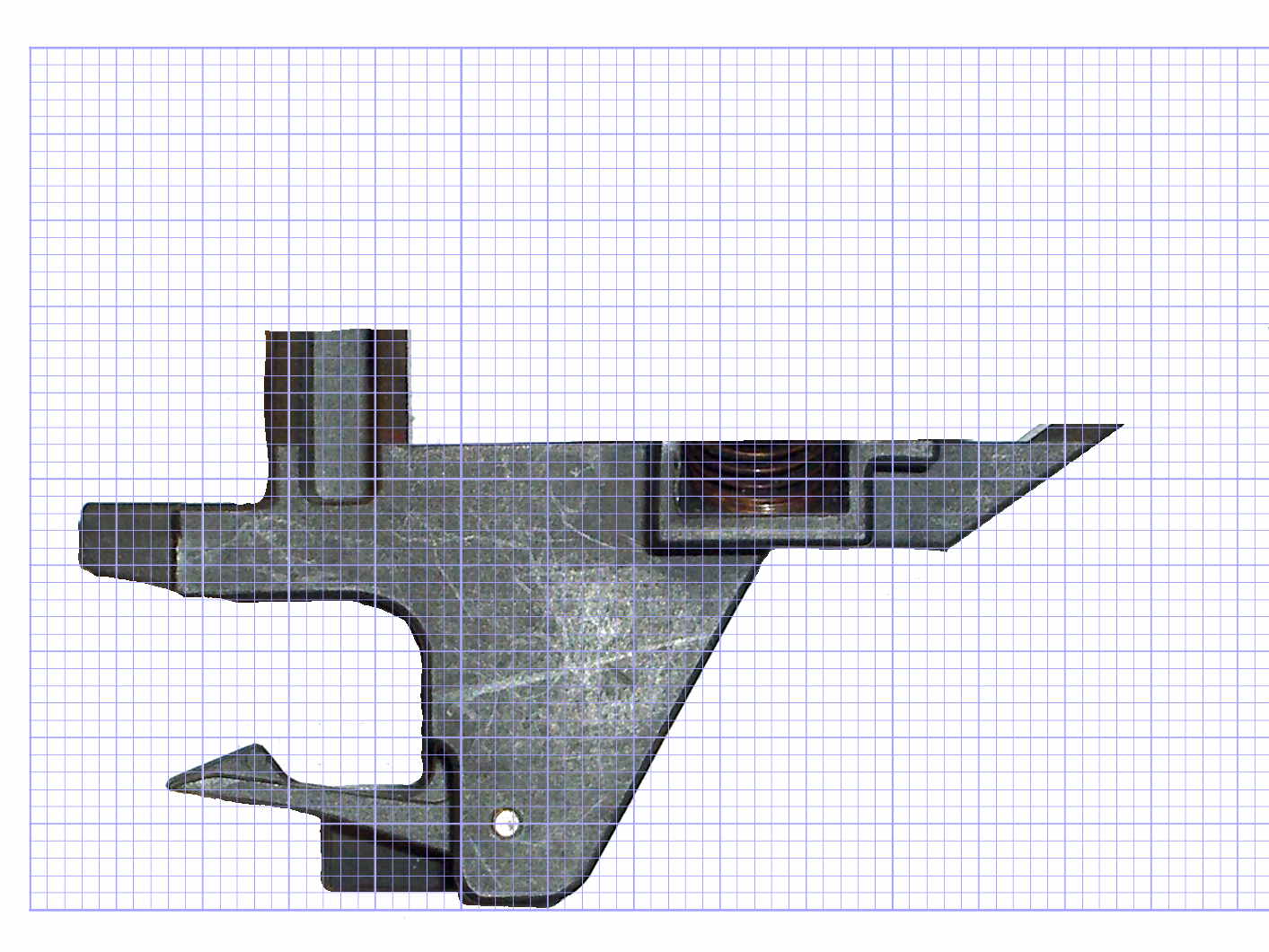
The carrier measures 26.8 mm front-to-back, so scaling a grid to match that dimension provides a coordinate system overlay:
HP7475A – pen holder – top view – 1 mm grid
The (0,0) origin sits at the lower left, so you can read off all the relevant coordinates as needed.
However, rather than go full-frontal digital, I resized the isolated image to 20 pixel/mm, turned it into a height map, and treated it like a chocolate mold or cookie cutter with gray values scaled to the desired height:
Black = background to be removed
Dark gray = 2.5 mm thick
Medium gray = 3.5 mm
Light gray = 7 mm
White = 10 mm
Drawing the walls with a 40 pixel diameter pen makes them 2 mm wide at 20 pixel/mm:
HP7475A – knife stabilizer
It’s painfully obvious why I don’t do much freehand drawing, although the knife adapter hole is supposed to be oval.
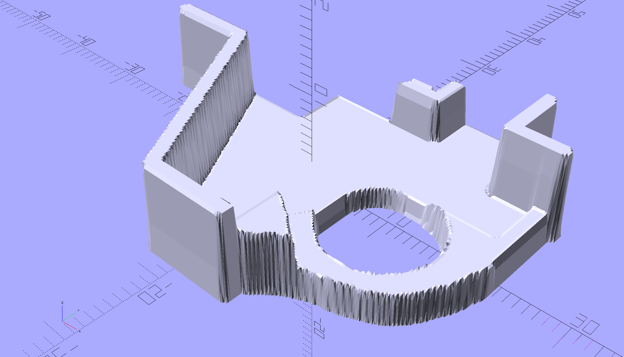
As with cookie cutters and chocolate molds, there’s no need for that much resolution, so I rescaled it to 4 pixel/mm, saved that tiny image as a PNG file, and handed it to OpenSCAD’s surface() function to get a solid model. This being a one-off, I typed this OpenSCAD source code directly into the OpenSCAD editor on the fly, then remembered to save it (!) before shutting down:
The mirror() transformation inverts the model top-to-bottom along the Z axis, compensating for the flip from drawing the height map as though the walls rise upward from the pen carrier, after which the flip() transformation puts the flat side down to make it buildable.
The height map image conversion produces a bazillion irrelevant faces, but it’s quick and easy:
HP7475A – Roland knife stabilizer – height map model
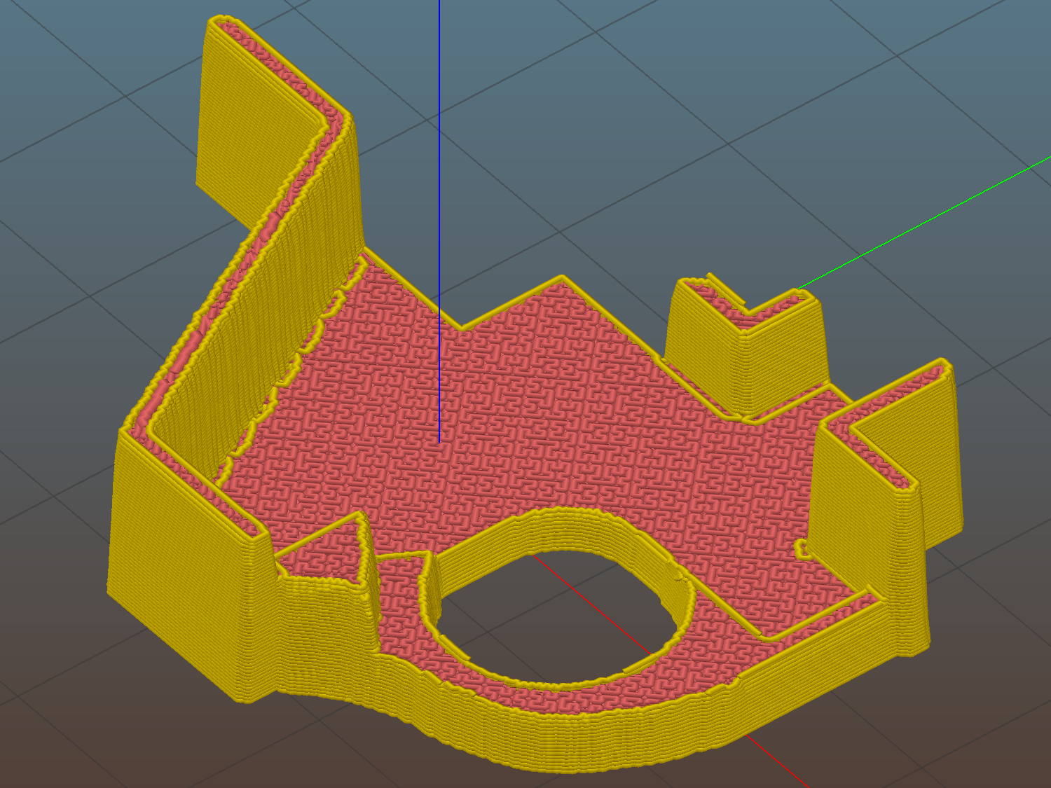
I’ve been using Slic3r’s Hilbert Curve pattern for top & bottom infill to get a nice textured result:
Roland knife stabilizer – height map – Slic3r preview
Which printed just about like you’d expect:
HP 7475A – Roland knife adapter and stabilizer – height map – bottom view
I reamed out the hole with a step drill (the HP pens are close enough to 7/16 as to make no difference here) to get the knife adapter to fit, but the walls and suchlike came out close enough.
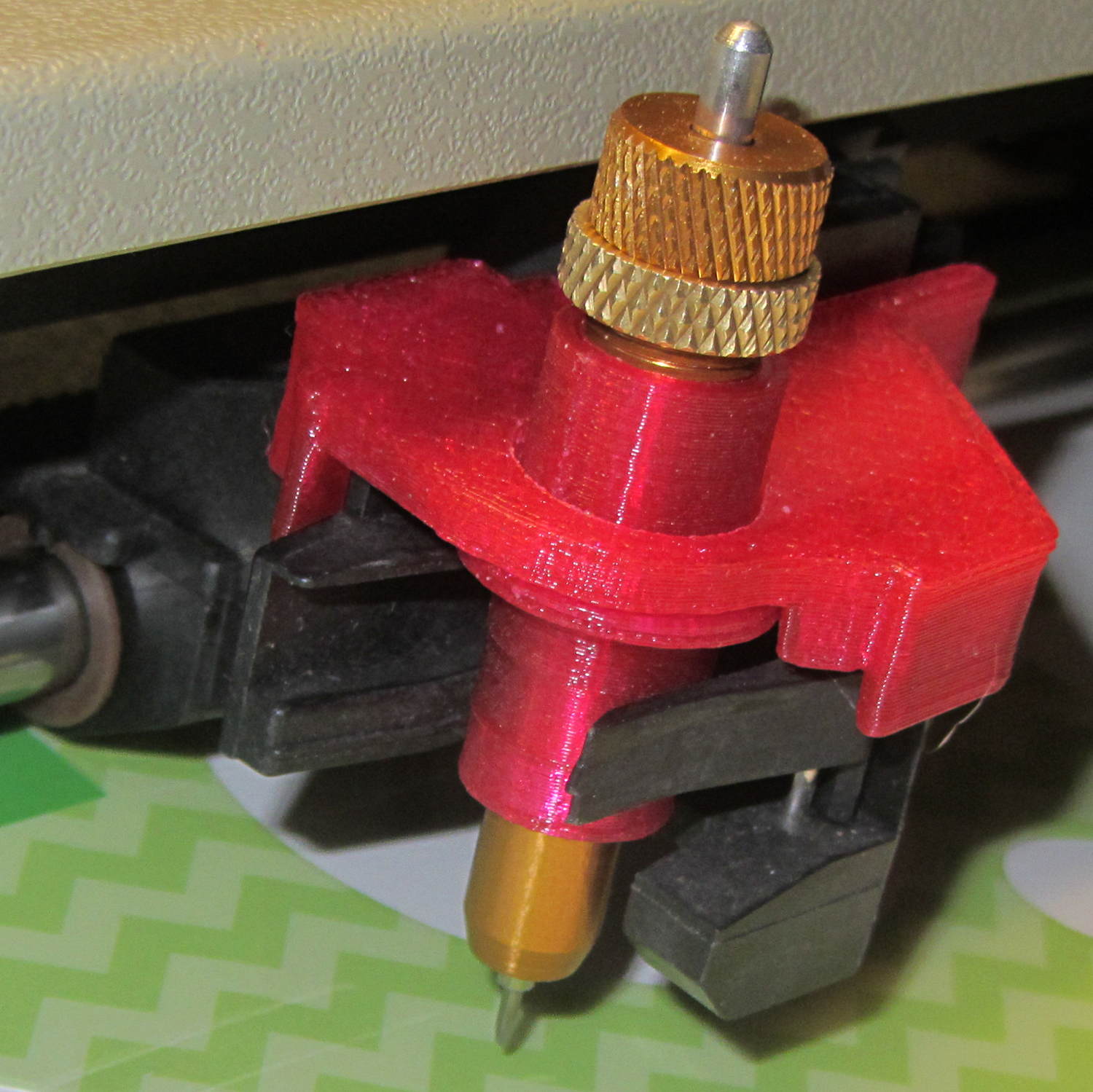
Then it just snapped into place:
HP 7475A – Roland knife adapter and stabilizer – height map
Actually, no, it didn’t just snap into place: some (dis)assembly was required.
First, remove the brass knife bearing from the adapter, push the knife adapter shell into the pen holder, slide the stabilizer cap down over the adapter, press it firmly around the pen holder, reinstall the brass knife bearing, then it’s ready.
The cuts in the green vinyl just to the left of the knife blade (in a window decoration sheet I spotted in a trash can) show that the blade can cut, albeit with some finger pressure, but the fancy red stabilizer didn’t stay stuck on the pen carrier nearly as well as I expected. A screw attachment will help with that, which calls for going all digital on those coordinates.
It’s the start of a new riding season and we’re returning from a concert at Vassar. I’m cranking 20+ mph, pushed by a gusty tailwind.
T minus 7 seconds:
Cedar Valley Rd – Left Cross – T-7
The white car approaches the intersection a bit faster than usual, which leads me to expect a New York State Rolling Stop-and-Go right turn directly in front of me.
T minus 5 seconds:
Cedar Valley Rd – Left Cross – T-5
The white car slows enough that I now expect a stop with the front end well onto the shoulder. A quick check in the mirror shows no traffic behind me: I can take the lane if needed. This intersection always has a large gravel patch spanning the shoulder, so I must move closer to the fog line anyway.
T minus 2 seconds:
Cedar Valley Rd – Left Cross – T-2
The white car comes to a full stop, not too far onto the shoulder, and my fingers come off the brakes. I gotta work on that fingers-up position, though.
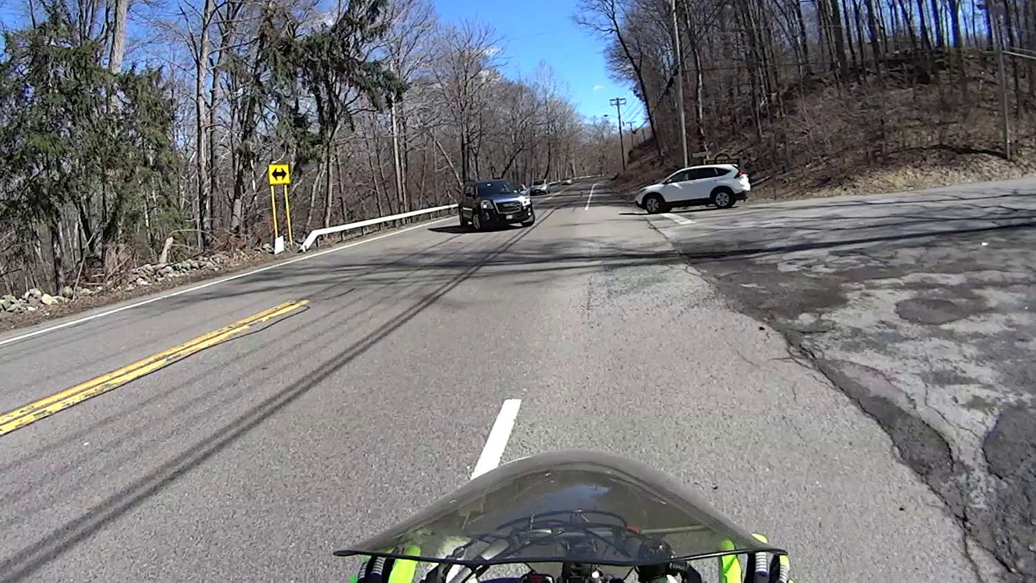
… Whoops, a classic left cross from the black SUV!
T minus 1 second:
Cedar Valley Rd – Left Cross – T-1
I’m now braking hard, barely to the left of the gravel patch.
T zero:
Cedar Valley Rd – Left Cross – T-0
Well, that was close.
Somewhat to my surprise, the white car hasn’t crept any further onto the shoulder.
The SUV driver gives me a cheery wave, as if to thank me for not scratching the doors. I never make hand gestures, but I did tell him he does nice work.
It is, apparently, easy to mis-judge a bike’s speed, although driver-ed courses used to recommend that you err on the side of not trying to beat an oncoming vehicle. Perhaps that recommendation has become inoperative?
The corresponding maneuver by a car passing you is known as a right hook.
Memo to Self: Always look at the license plate to give the camera a straight-on picture.
The trick depends on specifying the colors with HSB, rather than RGB, so that the buttons in each row have the same hue and differ in saturation and brightness. The Imagemagick incantations look like this:
Disabled: hsb\(${HUE}%,50%,40%\)
Unselected: hsb\(${HUE}%,100%,70%\)
Selected: hsb\(${HUE}%,100%,100%\)
For whatever reason, the hue must be a percentage if the other parameters are also percentages. At least, I couldn’t figure out how to make a plain integer without a percent sign suffix work as a degree value for hue.
Anyhow, in real life they look pretty good and make the selected buttons much more obvious:
The LCD screen looks just like that; I blew out the contrast on the surroundings to provide some context. The green square on the left is the Arduino Mega’s power LED, the purple dot on the right is the heartbeat spot.
The new “needle stop anywhere” symbol (left middle) is the White Draughts Man Unicode character: ⛀ = U+26C0. We call them checkers here in the US, but it’s supposed to look like a bobbin, as you must disengage the handwheel clutch and stop the main shaft when filling a bobbin; the needle positioning code depends on the shaft position sensor.
Weirdly, Unicode has no glyphs for sewing, not even a spool of thread, although “Fish Cake With Swirl” (🍥 = U+1F365) came close. Your browser must have access to a font with deep Unicode support in order to see that one…
This is mostly a test to see how long it takes before something on the RPi goes toes-up enough to require a manual reboot. Disabling the WiFi link’s power saving mode seems to keep the RPi on the air all the time, which is a start.
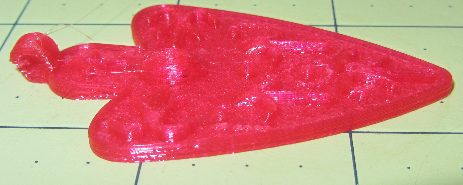
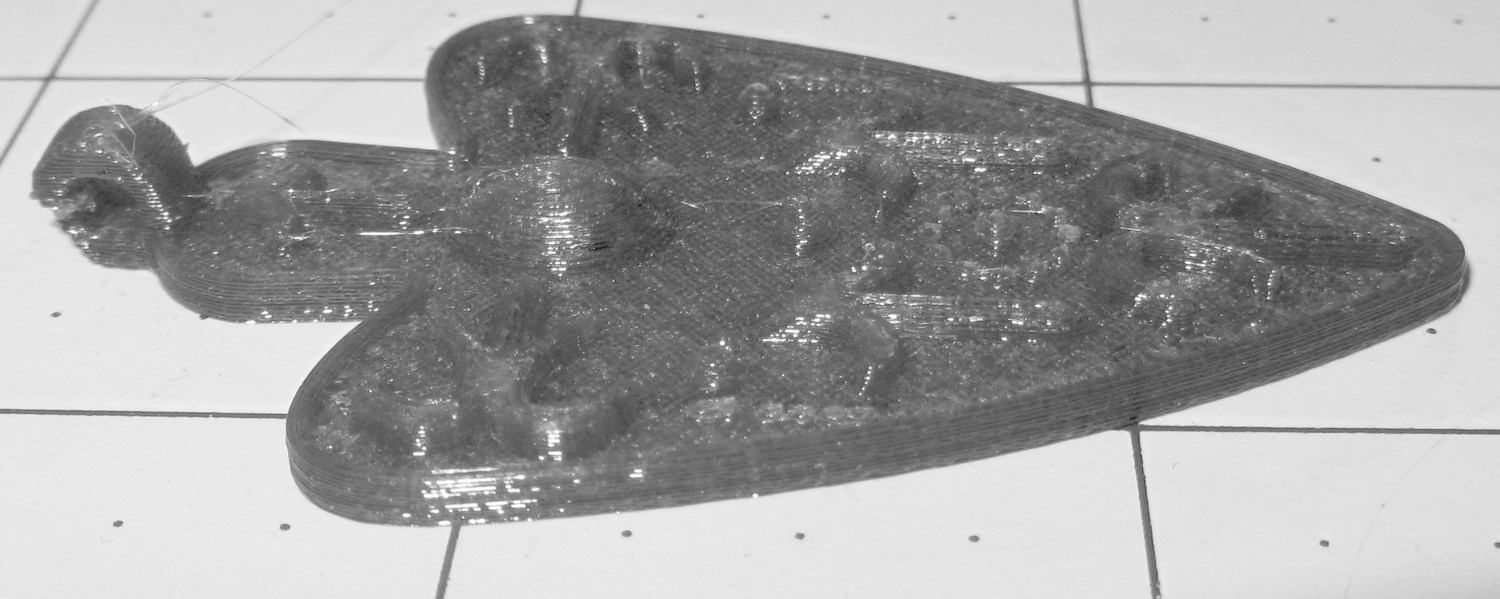
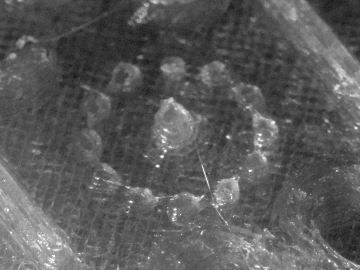
I also tried using the camera in its B&W mode to discard the color information up front:
Necklace Heart – circle detail
It’s taken through the macro adapter with the LEDs turned off and obviously benefits from better lighting, with an LED flashlight at grazing incidence. You can even see the Hilbert Curve top infill.
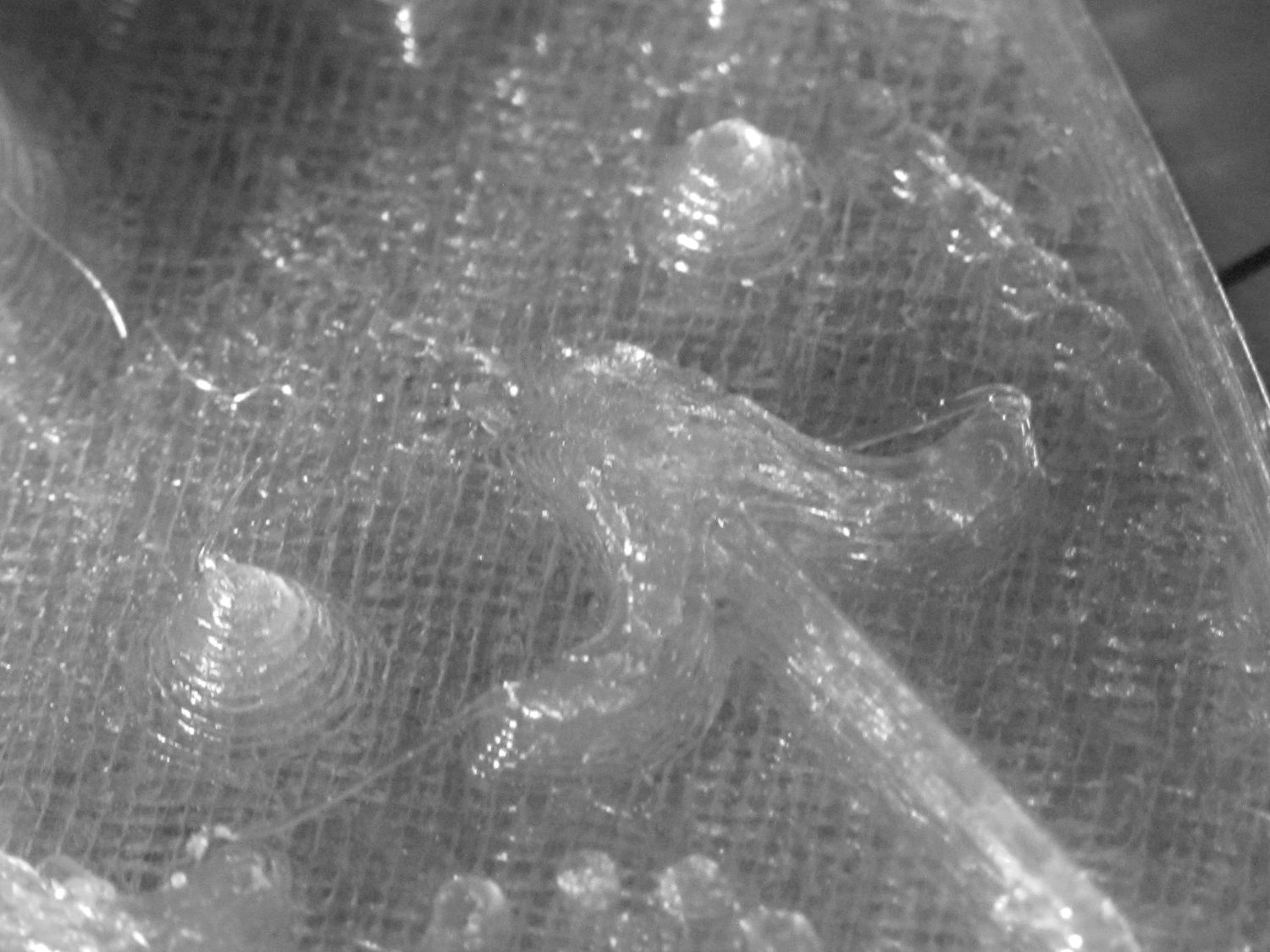
The object of the exercise was to see if those tiny dots would print properly, which they did:
Necklace Heart – dots detail
Now, admittedly, PETG still produces fine hairs, but those dots consist of two layers and two thread widths, so it’s a harsh retraction test.
A look at the other side:
Necklace Heart – detail
All in all, both the object and the pix worked out much better than I expected.
Leaving the camera in full color mode and processing the images in The GIMP means less fiddling with the camera settings, which seems like a net win.