Ed Nisley's Blog: Shop notes, electronics, firmware, machinery, 3D printing, laser cuttery, and curiosities. Contents: 100% human thinking, 0% AI slop.
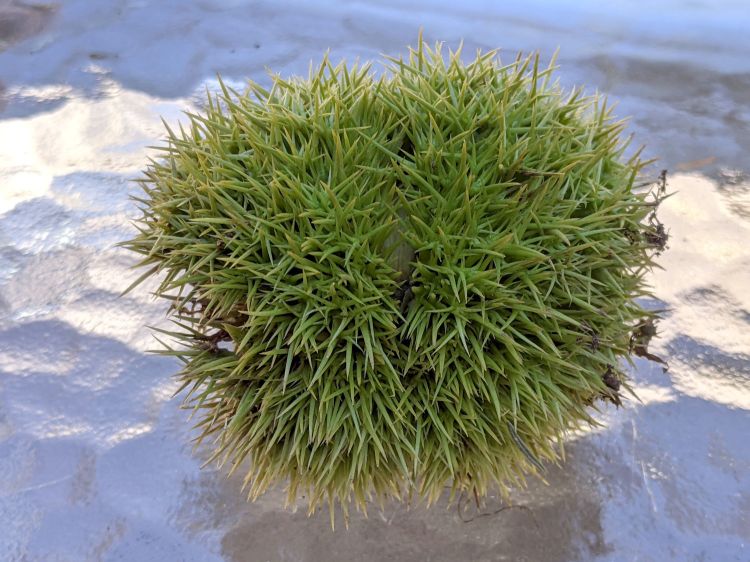
Much to our utter astonishment, this appeared on the driveway:
Chestnut burr
We’ve since found half a dozen chestnut burrs in the yard, which means at least two trees (it takes two to cross-fertilize) are growing in the immediate area.
We originally thought they were American Chestnuts, but Mary (being a Master Gardener) found enough references including comparative burr pictures to convince us they’re Chinese Chestnuts.
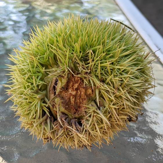
We’ve seen squirrels carrying the burrs in their mouths from the trees to wherever they bury their food supply, as shown by this gnawed spot on the other side of the burr:
Chestnut burr – gnawed section
I regard this as conclusive proof that squirrels either have no sense of pain or no lips, because I can’t imagine carrying that thing in my hand, let alone gnawing through it to extract the nuts inside.
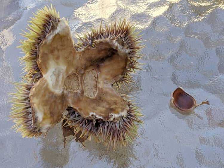
Each burr contains three nuts, although this empty husk shows some nuts can fail to fill out:
Chestnut burr – interior with failed nut
We don’t know where the trees are, but the squirrels seem to carry the burrs across our yard from north to south, so they can’t be too far from us or each other.
Despite our conclusion, it’s faintly possible they’re American Chestnuts, in which case they’re definitely survivors!
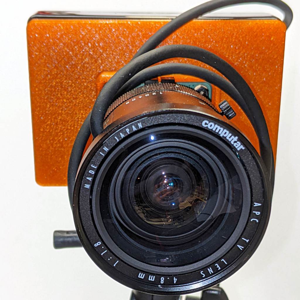
The Big Box o’ Optics disgorged an ancient new-in-box Computar 4.8 mm lens, originally intended for a TV camera, with a C mount perfectly suited for the Raspberry Pi HQ camera:
RPi HQ Camera – Computar 4.8mm – front view
Because it’s a video lens, it includes an aperture driver expecting a video signal from the camera through a standard connector:
Computar 4.8 mm lens – camera plug
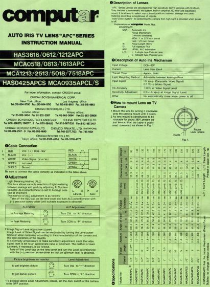
The datasheet tucked into the box (!) says it expects 8 to 16 V DC on the red wire (with black common) and video on white:
Computar Auto Iris TV Lens Manual
Fortunately, applying 5 V to red and leaving white unconnected opens the aperture all the way. Presumably, the circuitry thinks it’s looking at a really dark scene and isn’t fussy about the missing sync pulses.
Rather than attempt to find / harvest a matching camera connector, the cord now terminates in a JST plug, with the matching socket hot-melt glued to the Raspberry Pi case:
RPi HQ Camera – 4.8 mm Computar lens – JST power
The Pi has +5 V and ground on the rightmost end of its connector, so the Computar lens will be jammed fully open.
I gave it something to look at:
RPi HQ Camera – Computar 4.8mm – overview
With the orange back plate about 150 mm from the RPi, the 4.8 mm lens delivers this scene:
RPi HQ Camera – 4.8 mm Computar lens – 150mm near view
The focus is on the shutdown / startup button just to the right of the heatsink, so the depth of field is maybe 25 mm front-to-back.
For comparison, the official 16 mm lens stopped down to f/8 has a tighter view with good depth of field:
RPi HQ Camera – 16 mm lens – 150mm near view
It’d be nice to have a variable aperture, but it’s probably not worth the effort.
Despite the company name, the Arducam 5 MP Motorized Focus camera plugs into a Raspberry Pi’s camera connector and lives on a PCB the same size as ordinary RPi cameras:
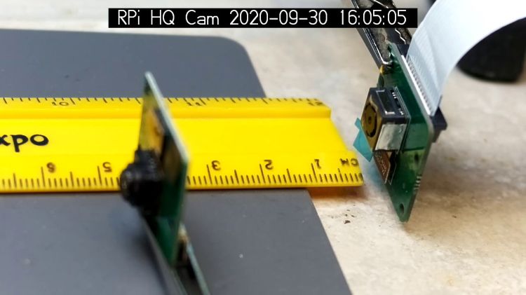
Arducam Motorized Focus RPi Camera – test overview
That’s a focus test setup to get some idea of how the control values match up against actual distances.
It powers up focused at infinity (or maybe a bit beyond):
Arducam Motorized Focus RPi Camera – default focus
In practice, it’s a usable, if a bit soft, at any distance beyond a couple of meters.
The closest focus is around 40 mm, depending on where you set the ruler’s zero point:
Pondering the sample code shows the camera focus setting involves writing two bytes to an I²C address through the video controller’s I²C bus. Enable that bus with a line in /boot/config.txt:
dtparam=i2c_vc=on
If you’re planning to capture 1280×720 or larger still images, reserve enough memory in the GPU:
gpu_mem=512
I don’t know how to determine the correct value.
And, if user pi isn’t in group i2c, make it so, then reboot.
The camera must be running before you can focus it, so run raspivid and watch the picture. I think you must do that in order to focus a (higher-res) still picture, perhaps starting a video preroll (not that kind) in a different thread while you fire off a (predetermined?) focus value, allow time for the lens to settle, then acquire a still picture with the video still running.
The focus value is number between 0 and 1023, in two bytes divided, written in big-endian order to address 0x0c on bus 0:
i2cset -y 0 0x0c 0x3f 0xff
You can, of course, use decimal numbers:
i2cset -y 0 0x0c 63 255
I think hex values are easier to tweak by hand.
Some tinkering gives this rough correlation:
Focus value (hex)
Focus distance (mm)
3FFF
45 (-ish)
3000
55
2000
95
1000
530
0800
850
Arducam Motorized Focus Camera – numeric value vs mm
Beyond a meter, the somewhat gritty camera resolution gets in the way of precise focusing, particularly in low indoor lighting.
A successful write produces a return code of 0. Sometimes the write will inexplicably fail with an Error: Write failed message, a return code of 1, and no focus change, so it’s Good Practice to retry until it works.
This obviously calls for a knob and a persistent value!
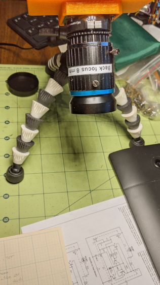
Part of the motivation for getting a Raspberry Pi HQ camera sensor was being able to use lenses with adjustable focus and aperture, like the Official 10 MP “telephoto” lens:
RPi HQ Camera – aperture demo setup
Yes, it can focus absurdly close to the lens, particularly when you mess around with the back focus adjustment.
With the aperture fully open at f/1.4:
RPi HQ Camera – aperture demo – f 1.4
Stopped down to f/16:
RPi HQ Camera – aperture demo – f 16
The field of view is about 60 mm (left-to-right) at 150 mm. Obviously, arranging the camera with its optical axis more-or-less perpendicular to the page will improve everything about the image.
For normal subjects at normal ranges with normal lighting, the depth of field works pretty much the way you’d expect:
At f/1.4, focused on the potted plants a dozen feet away:
Raspberry Pi HQ Camera – outdoor near focus
Also at f/1.4, focused on the background at infinity:
Raspberry Pi HQ Camera – outdoor far focus
In comparison, the laptop camera renders everything equally badly (at a lower resolution, so it’s not a fair comparison):
None of this is surprising, but it’s a relief from the usual phone sensor camera with fixed focus (at “infinity” if you’re lucky) and a wide-open aperture.
The NYS DOT has been improving the pedestrian crossings at the Burnett – Rt 55 intersection. I expect this will be a bullet item in their Complete Streets compliance document, with favorable job reviews for all parties. The situation for bicyclists using the intersection, which provides the only access from Poughkeepsie to the Dutchess Rail Trail, hasn’t changed in the slightest. No signal timing adjustments, no bike-capable sensor loops, no lane markings, no shoulders, no nothing.
Here’s what NYS DOT’s Complete Streets program looks like from our perspective, with the four-digit frame numbers ticking along at 60 frame/sec.
We’re waiting on Overocker Rd for Burnett traffic to clear enough to cross three lanes from a cold start:
Burnett Signal – 2020-09-25 – front 0006
That building over there across Burnett is the NYS DOT Region 8 Headquarters, so we’re not in the hinterlands where nobody ever goes.
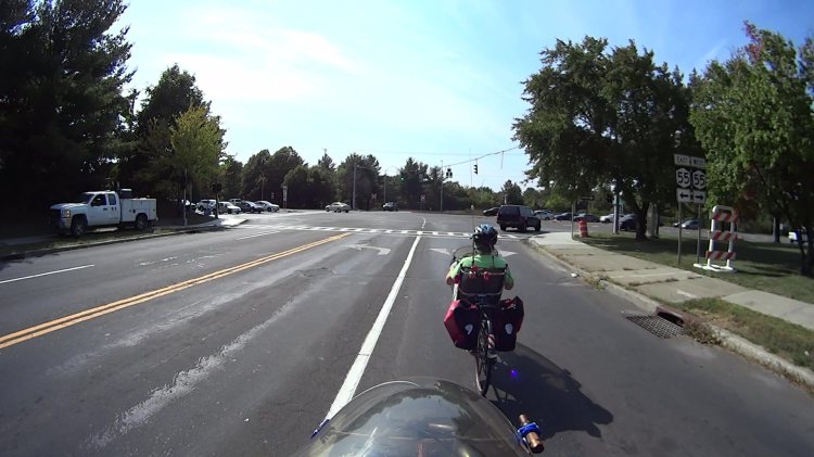
About 1.5 seconds later, the vehicles have started moving and we’re lining up for the left side of the right-hand lane:
Burnett Signal – 2020-09-25 – front 0752
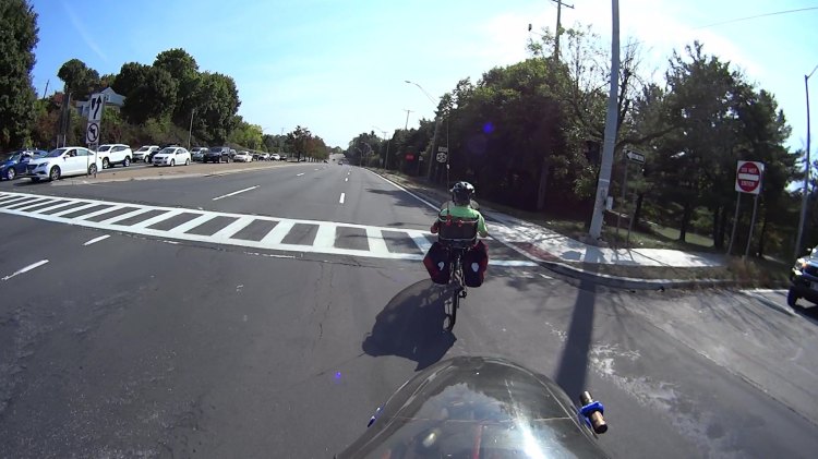
There’s no traffic behind us, so we can ride a little more to the right than we usually do, in the hopes of triggering the signal’s unmarked sensor loop:
Burnett Signal – 2020-09-25 – front 1178
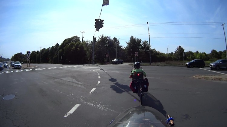
We didn’t expect anything different:
Burnett Signal – 2020-09-25 – front 1333
We’re rolling at about 12 mph and it’s unreasonable to expect us to jam to a stop whenever the signal turns yellow. Oh, did you notice the truck parked in the sidewalk over on the left?
As usual, 4.3 seconds later, the Burnett signals turn red, so we’re now riding in the “intersection clearing” delay:
One second later, we’re still proceeding through the intersection, clearing the lethally smooth manhole cover by a few inches, and approaching the far side:
Burnett Signal – 2020-09-25 – front 1771
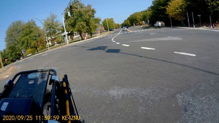
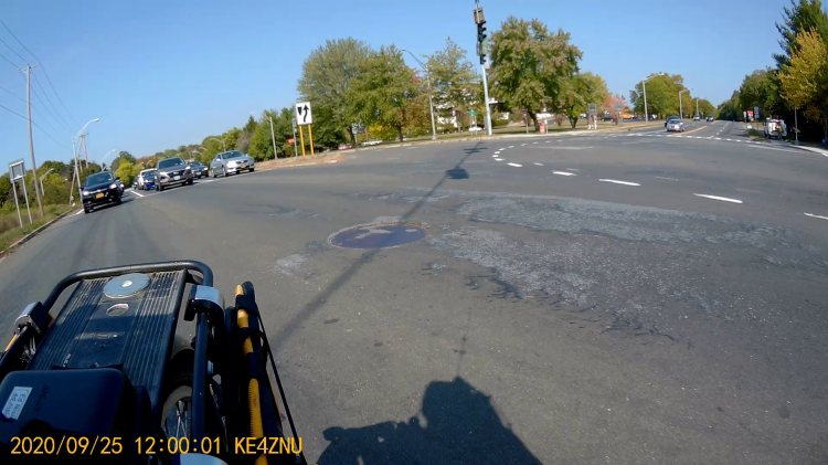
Here’s what the intersection looks like behind me:
Burnett Signal – 2020-09-25 – rear 1
Another second goes by and we’re pretty much into the far right lane , with the westbound traffic beginning to move:
Burnett Signal – 2020-09-25 – front 1831
The pedestrian crossing ladder has fresh new paint. They milled off the old paint while reconstructing the crossing, so the scarred asphalt will deteriorate into potholes after a few freeze-thaw cycles. Not their problem, it seems.
Although it’s been three seconds since Rt 55 got a green signal, the eastbound drivers remain stunned by our presence:
Burnett Signal – 2020-09-25 – rear 2
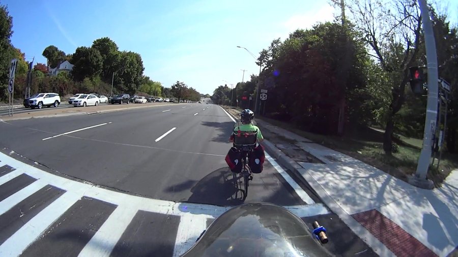
After another second, we’re almost where we need to be:
Burnett Signal – 2020-09-25 – front 1891
There’s a new concrete sidewalk on the right, with a wheelchair-accessible signal button I can now hit with my elbow when we’re headed in the other direction. It’s worth noting there is no way to reach Overocker by bicycle, other than riding the sidewalk; there’s only one “complete” direction for vehicular cyclists.
One second later puts us as far to the right as we can get, given all the gravel / debris / deteriorated asphalt along the fog line near the curb:
Burnett Signal – 2020-09-25 – front 1957
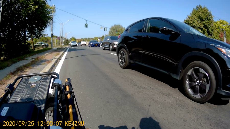
Which is good, because four seconds after the green signal for Rt 55, the pack has overtaken us:
Burnett Signal – 2020-09-25 – rear 3
If you were the driver of the grayish car in the middle lane, directly behind the black one giving us plenty of room, you might be surprised at the abrupt lane change in front of you. Maybe not, because you had a front-row seat while we went through the intersection.
Elapsed time from the green signal on Burnett: 25 seconds. My point is that another few seconds of all-red intersection clearing time wouldn’t materially affect anybody’s day and would go a long way toward improving bicycle safety.
Unlike the pedestrian crossing upgrade, NYS DOT could fix this with zero capital expenditure: one engineer with keys to the control box, a screwdriver or keyboard (depending on the age of the controls), and the ability to do the right thing could fix it before lunch tomorrow.
Rummaging through the Big Box o’ Optics in search of something else produced this doodad:
Microscope objective illuminator – overview
It carries no brand name or identifier, suggesting it was shop-made for a very specific and completely unknown purpose. The 5× objective also came from the BBo’O, but wasn’t related in any way other than fitting the threads, so the original purpose probably didn’t include it.
The little bulb fit into a cute and obviously heat-stressed socket:
Microscope objective illuminator – bulb detail
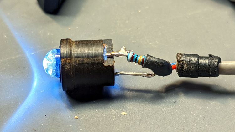
The filament was, of course, broken, so I dismantled the socket and conjured a quick-n-dirty white LED that appears blue under the warm-white bench lighting:
Microscope objective illuminator – white LED
The socket fits into the housing on the left, which screws onto a fitting I would have sworn was glued / frozen in place. Eventually, I found a slotted grub screw hidden under a glob of dirt:
Microscope objective illuminator – lock screw
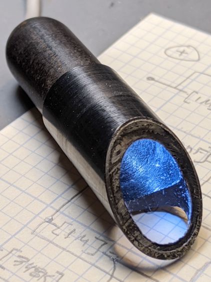
Releasing the screw let the fitting slide right out:
Microscope objective illuminator – lamp reflector
The glass reflector sits at 45° to direct the light coaxially down into the objective (or whatever optics it was originally intended for), with the other end of the widget having a clear view straight through. I cleaned the usual collection of fuzz & dirt off the glass, then centered and aligned the reflection with the objective.
Unfortunately, the objective lens lacks antireflection coatings:
Microscope objective illuminator – stray light
The LED tube is off to the right at 2 o’clock, with the bar across the reflector coming from stray light bouncing back from the far wall of the interior. The brilliant dot in the middle comes from light reflected off the various surfaces inside the objective.
An unimpeachable source tells me microscope objectives are designed to form a real image 180 mm up inside the ‘scope tube with the lens at the design height above the object. I have the luxury of being able to ignore all that, so I perched a lensless Raspberry Pi V1 camera on a short brass tube and affixed it to a three-axis positioner:
Microscope objective illuminator – RPi camera lashup
A closer look at the lashup reveals the utter crudity:
Microscope objective illuminator – RPi camera lashup – detail
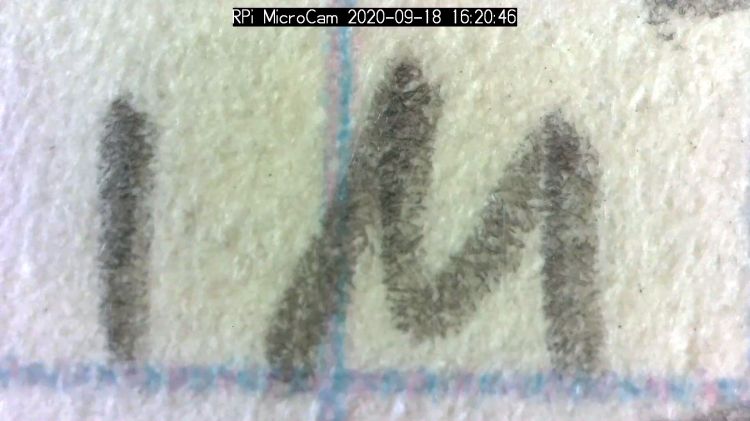
It’s better than I expected:
Microscope objective illuminator – RPi V1 camera image – unprocessed
What you’re seeing is the real image formed by the objective lens directly on the RPi V1 camera’s sensor: in effect, the objective replaces the itsy-bitsy camera lens. It’s a screen capture from VLC using V4L2 loopback trickery.
Those are 0.1 inch squares printed on the paper, so the view is about 150×110 mil. Positioning the camera further from the objective would reduce both the view (increase the magnification) and the amount of light, so this may be about as good as it get.
The image started out with low contrast from all the stray light, but can be coerced into usability:
The weird violet-to-greenish color shading apparently comes from the lens shading correction matrix baked into the RPi image capture pipeline and can, with some difficulty, be fixed if you have a mind to do so.
As far as I can tell, Raspberry Pi cases are a solved problem, so 3D printing an intricate widget to stick a Pi on the back of an HQ camera seems unnecessary unless you really, really like solid modeling, which, admittedly, can be a thing. All you really need is a simple adapter between the camera PCB and the case of your choice:
The plate has recesses to put the screw heads below the surface. I used nylon screws, but it doesn’t really matter.
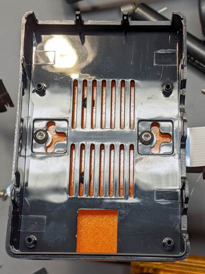
The case has all the right openings, slots in the bottom for a pair of screws, and costs six bucks. A pair of M3 brass inserts epoxied into the plate capture the screws:
RPi HQ Camera – case adapter plate – screws
Thick washers punched from an old credit card go under the screws to compensate for the case’s silicone bump feet. I suppose Doing the Right Thing would involve 3D printed spacers matching the cross-shaped case cutouts.
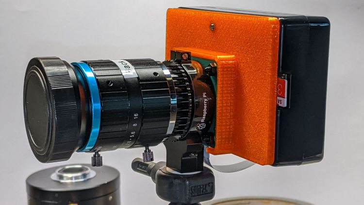
Not everyone agrees with my choice of retina-burn orange PETG:
RPi HQ Camera – 16 mm lens – case adapter plate
Yes, that’s a C-mount TV lens lurking in the background, about which more later.
This file contains hidden or bidirectional Unicode text that may be interpreted or compiled differently than what appears below. To review, open the file in an editor that reveals hidden Unicode characters.
Learn more about bidirectional Unicode characters