Ed Nisley's Blog: Shop notes, electronics, firmware, machinery, 3D printing, laser cuttery, and curiosities. Contents: 100% human thinking, 0% AI slop.
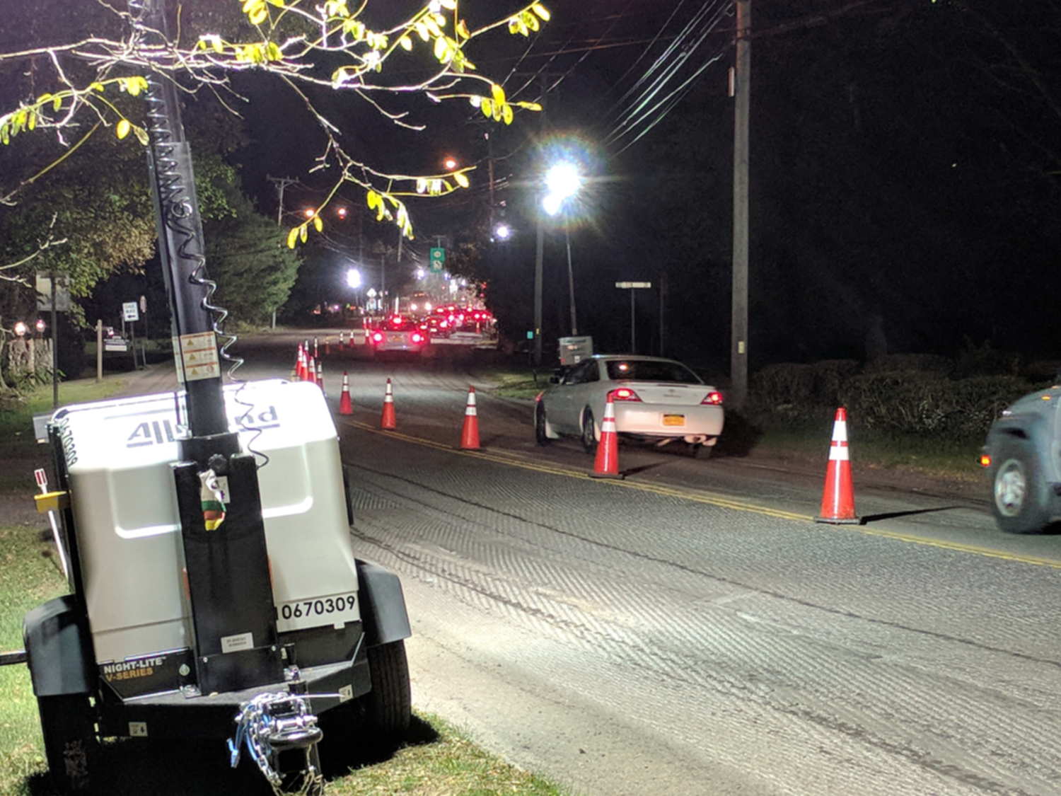
NYS DOT repaved the section of Rt 376 between our house and the Red Oaks Mill intersection during a mid-October week, doing most of the work overnight to avoid jamming traffic to the horizon in all directions. Having nothing better to do, I supervised the proceedings …
They prepared the surface by milling off the old pavement during three successive nights, which was just about as noisy as you’d think:
Rt 376 Repave – milled surface
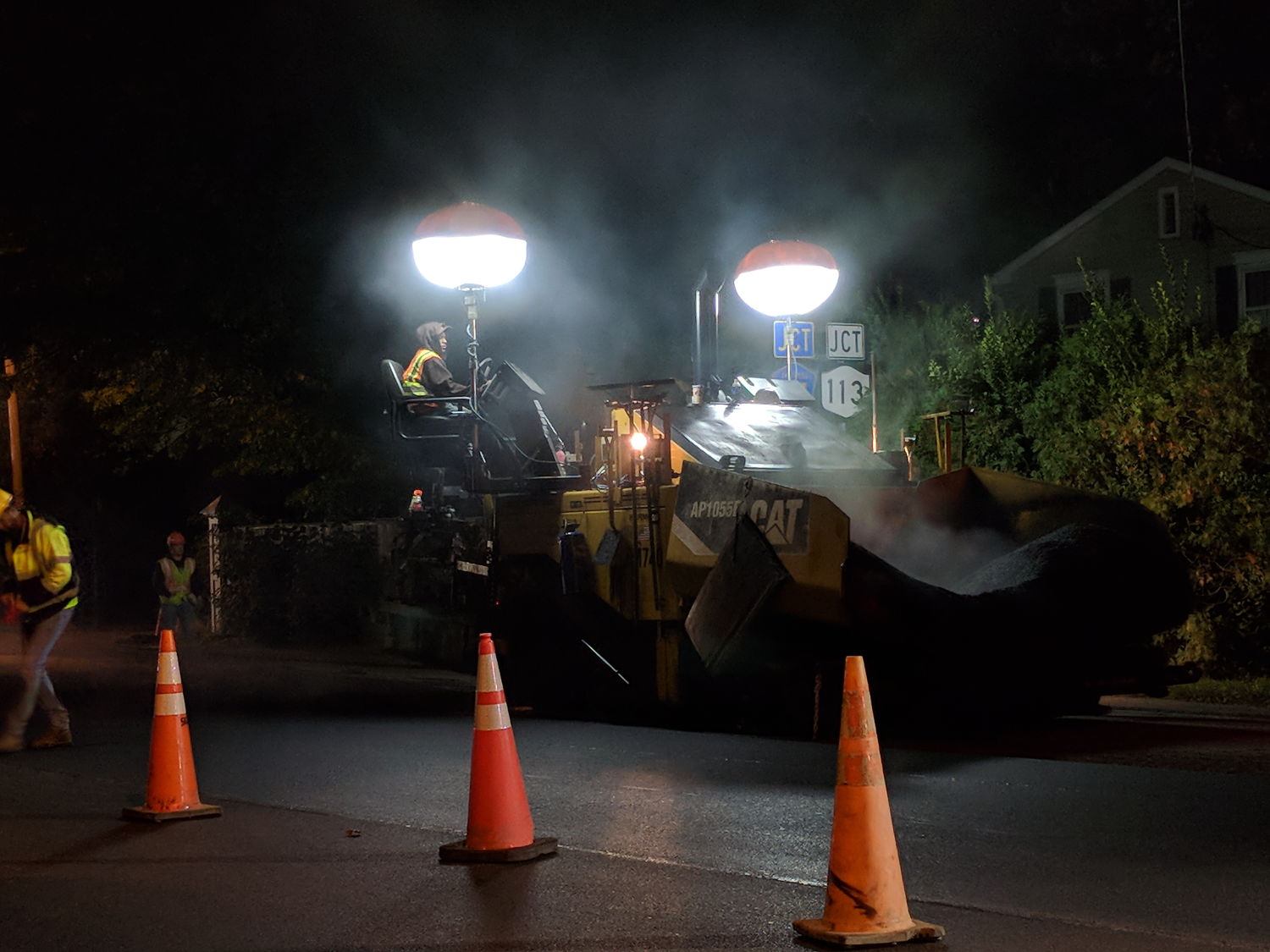
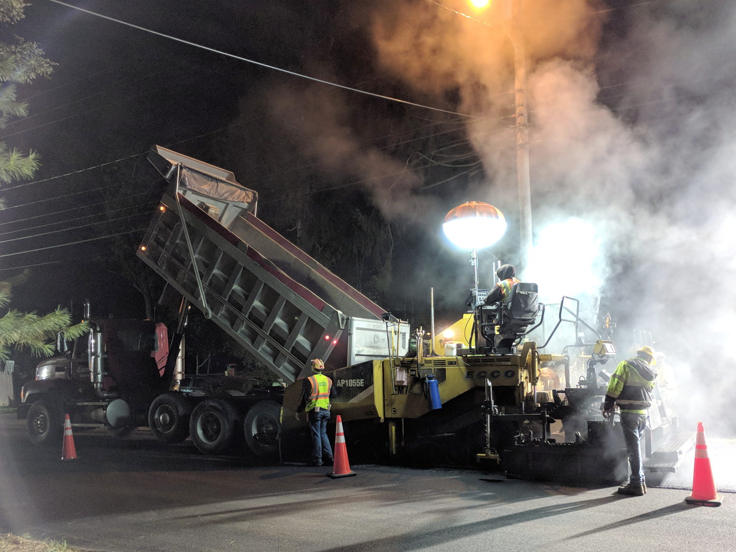
The asphalt spreader sported bizarre LED lights:
Rt 376 Repave – Spreader in Wait
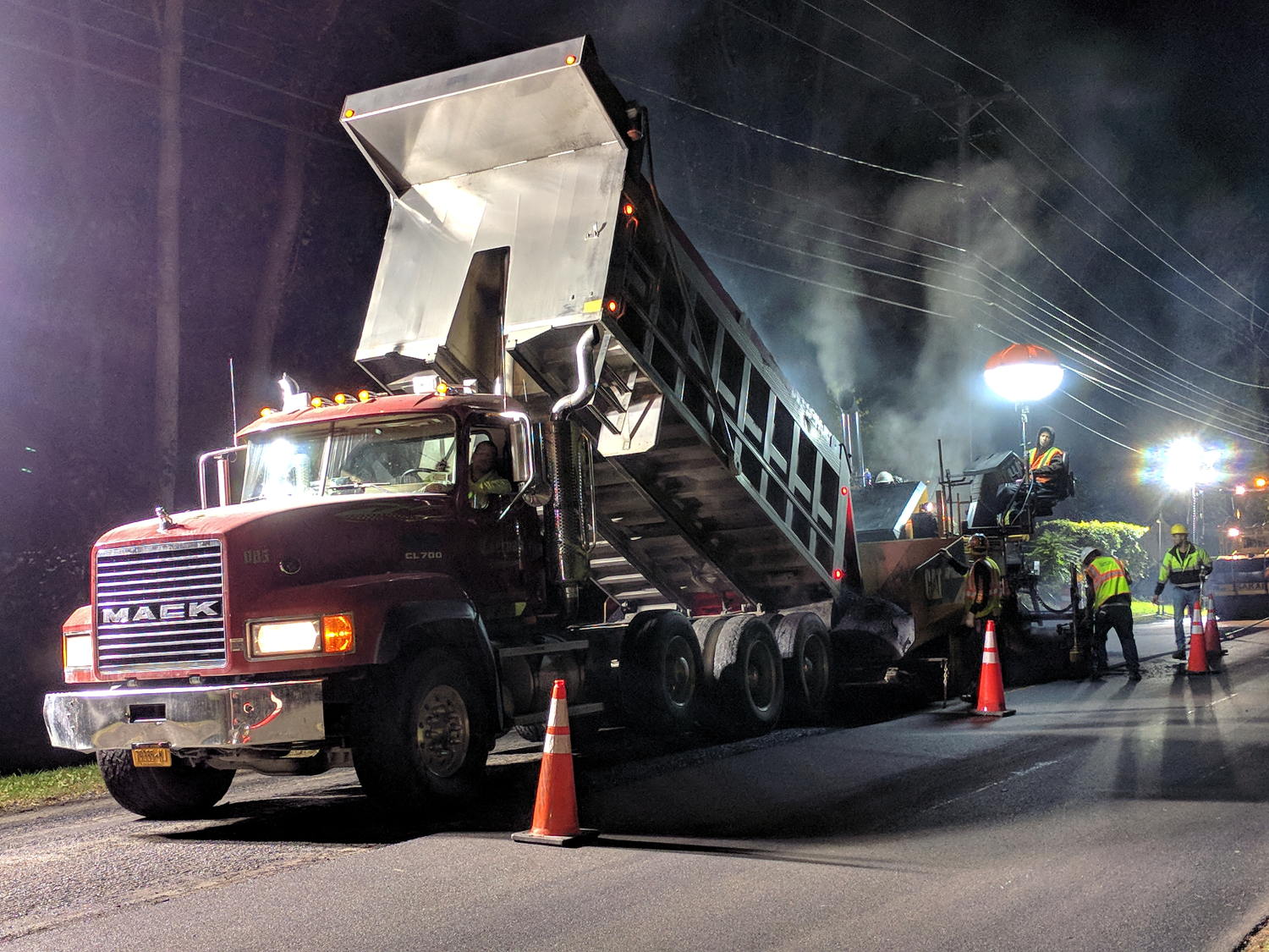
Southbound paving began with a crisp new truck:
Rt 376 Repave – Starting southbound
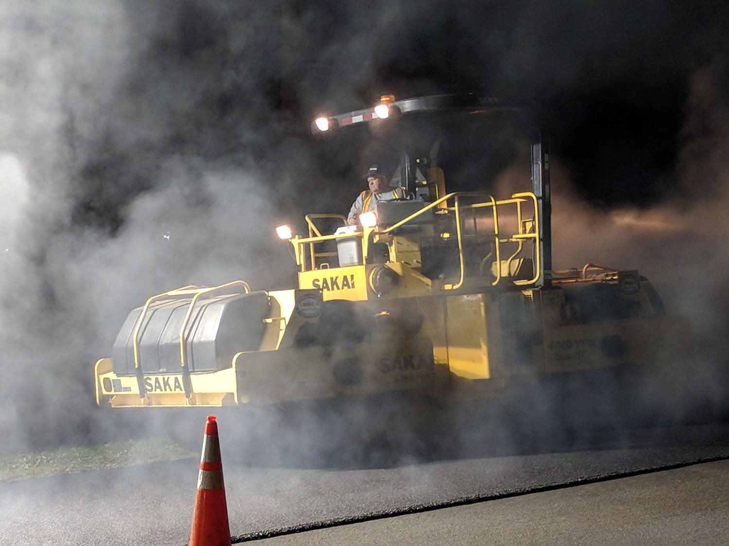
He would look the same rolling a highway straight through Hades:
Rt 376 Repave – Rolling
The short truck cleared the overhead wire:
Rt 376 Repave – Southbound under wire
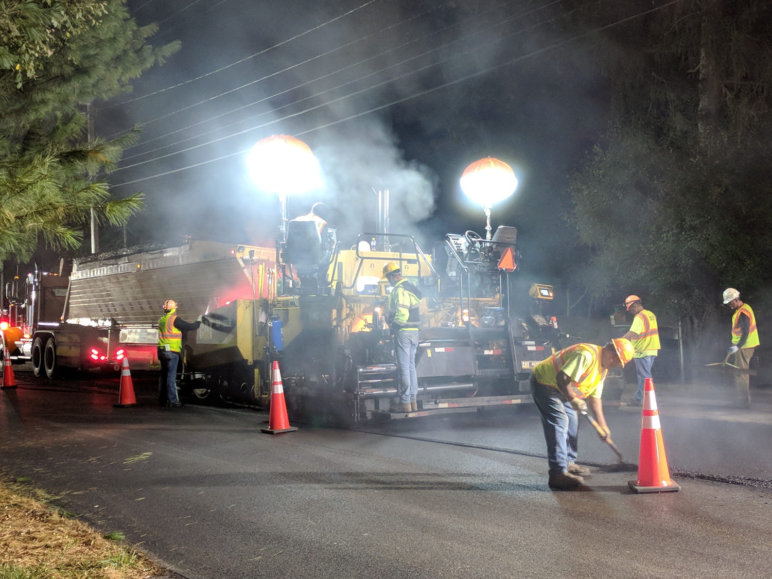
Then they chucked up a series of longer Flow Boy trailers:
Rt 376 Repave – Feathering the Edge
Despite all the machinery, the job requires guys with rakes and shovels.
All the pictures come from the Pixel, hand-held with automagic exposure and HDR+.
My tax dollars were definitely awake and hard at work during those nights!
I recently bought a pair of pork belly packages, one labeled “Local” at an additional buck a pound. They were packaged skin side downward, so the USDA inspection stamps came as a surprise:
Pork Belly Skin – USDA Stamps
Turns out the digits give the “establishment number”, which you can look up online. These came from a processor in Pine Plains.
We presume they keep track of their pigs …
The meat is curing even as I type. Next week: smoking.
This story unfolded over the course of three weeks:
USPS Tracking
After the package visited Poughkeepsie for the second time, I contacted the local delivery manager. He was absolute baffled as to what was going on, but promised to intercept it and give me a call when it returned.
When I called on 22 November, I got somebody else who was also completely baffled. However, she could view a scan of the package and noticed an odd mismatch:
The package tracking info showed my name and street address
The tracking info had my email address
The package label had somebody else’s name & address in Rensselaer
As best as I can follow the explanation, automated routing machinery at each facility scans each incoming package and shunts it to a conveyor belt filling a bin, thence to a truck, and away toward wherever it’s going. Alas, the (bogus) tracking info associated with this particular package aimed it toward me in Poughkeepise, but, when it arrived, a human read the actual label and tossed it in the bin headed toward Rensselaer.
Upon arriving in Renselaer, the automation fired it back toward Poughkeepsie.
Lather, rinse, repeat.
I buy plenty of “made in China” things, many shipped with tracking numbers, and tracking generally works the way you’d expect. Sometimes, however, the shipper does not tell me the tracking number and the first I learn of it is when tracking emails begin arriving from USPS. In other cases, no USPS facility along the way scans the package, whereupon the first notification I get happens when I open my mailbox and see the package.
In this case, I hadn’t bought anything close to the time when it would have been shipped and the tracking number didn’t correspond to any of my orders.
If this were an isolated incident, I’d shrug it off, but over the last year or two this is the third or fourth time this has happened, with packages from different Chinese sellers and another shipped from Arizona to Tennessee.
There was also a certified mail piece addressed to somebody at a nearby (easily typo-ed) address, delivered to our mailbox, but tracked as “handed to resident”. Whoops, indeed.
In all those cases, I got the tracking information from USPS, but the packages went directly to their destination. The extensive looping for this package was definitely a New Thing.
Nobody can explain how I (and my address!) get associated with these packages:
It’s obviously not a problem at the source, as I have no idea who the sellers / shippers are
To the best of my knowledge, they don’t know me, because their addresses aren’t familiar
The notices come directly from the USPS, so they’re associating me with a random package
It’s not a fault on my end, because I haven’t bought the items and don’t know they’re coming
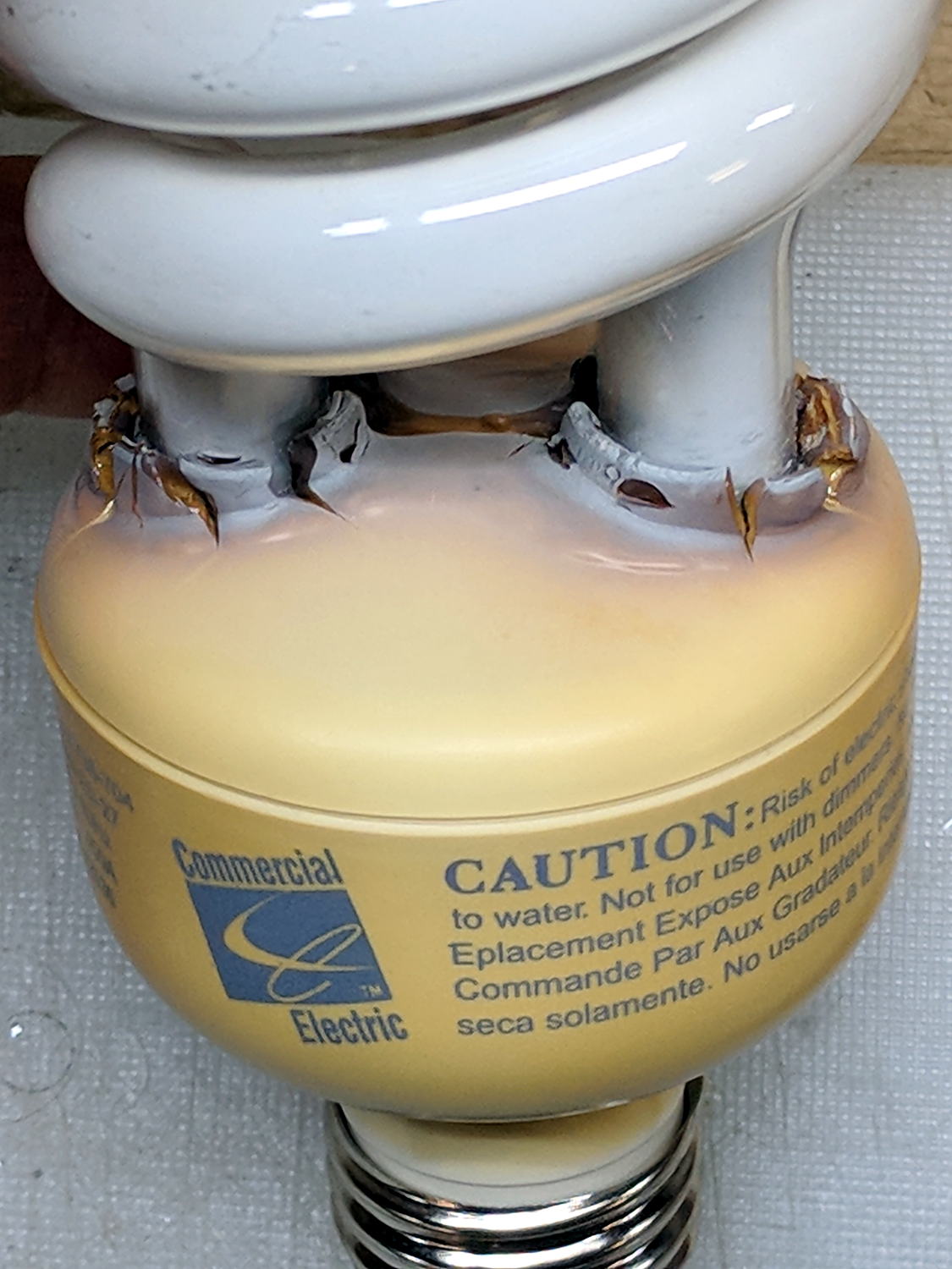
The straight-ish crack between the tube ends looks like it happened as the (yellowed) plastic ruptured and hardened.
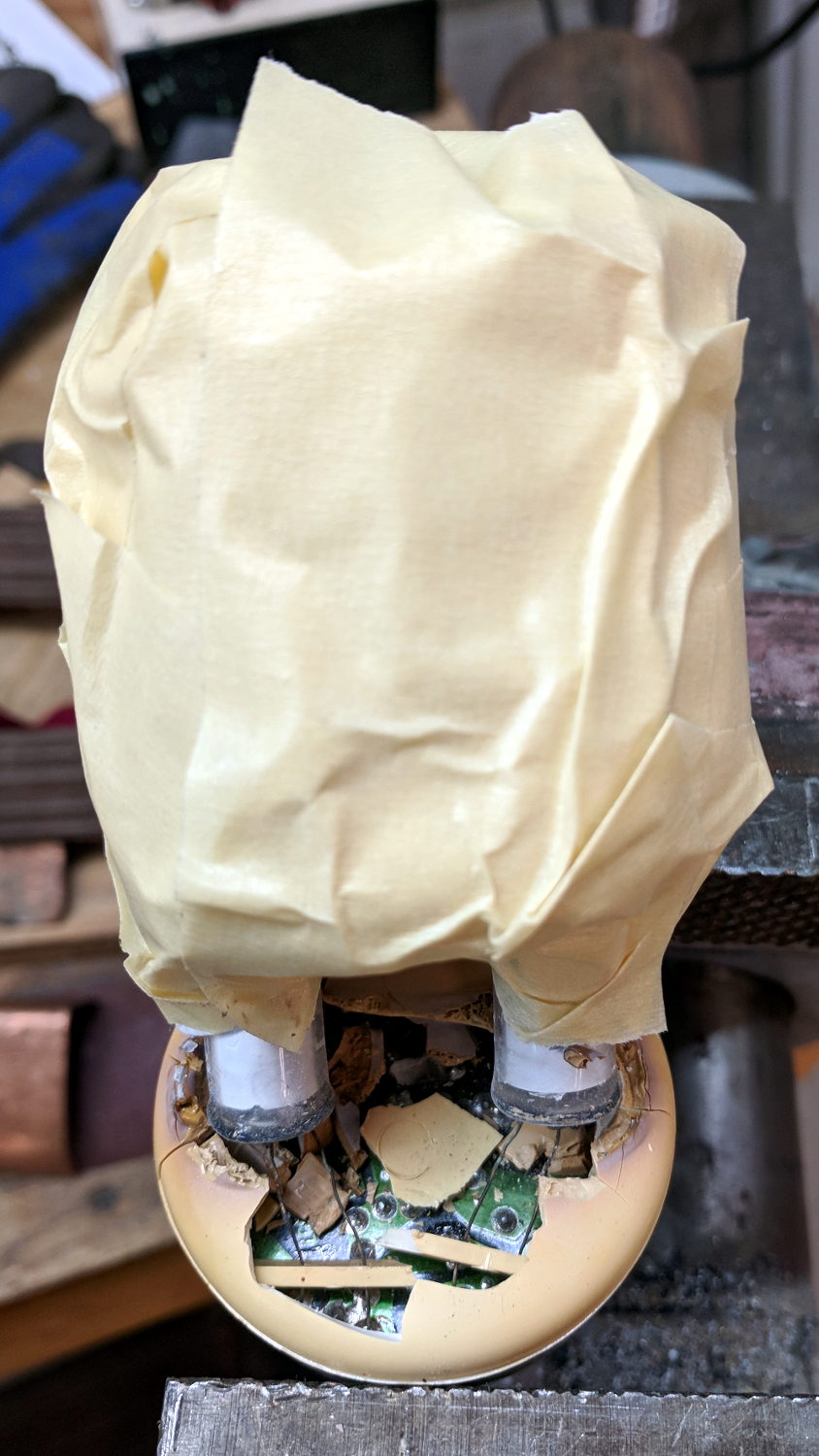
Not wanting to get a face full of glass fragments spiced with metallic mercury, I wrapped a blast shield around the spiral tube:
Failed CFL – tube wrap – shattered base
The terminal ends fit loosely in the crumbling base at the start of this operation, leaving the tube wobbling above the base. The plastic cracked as I wrapped the tube, so, for lack of anything smarter, I applied a pin punch to break away the rest of the upper base.
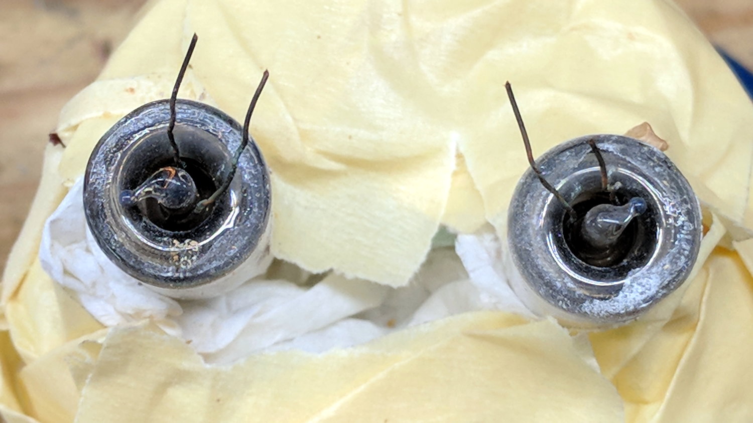
The tube doesn’t fit into a socket, of course, and terminates in four wire connections:
Failed CFL – tube terminals
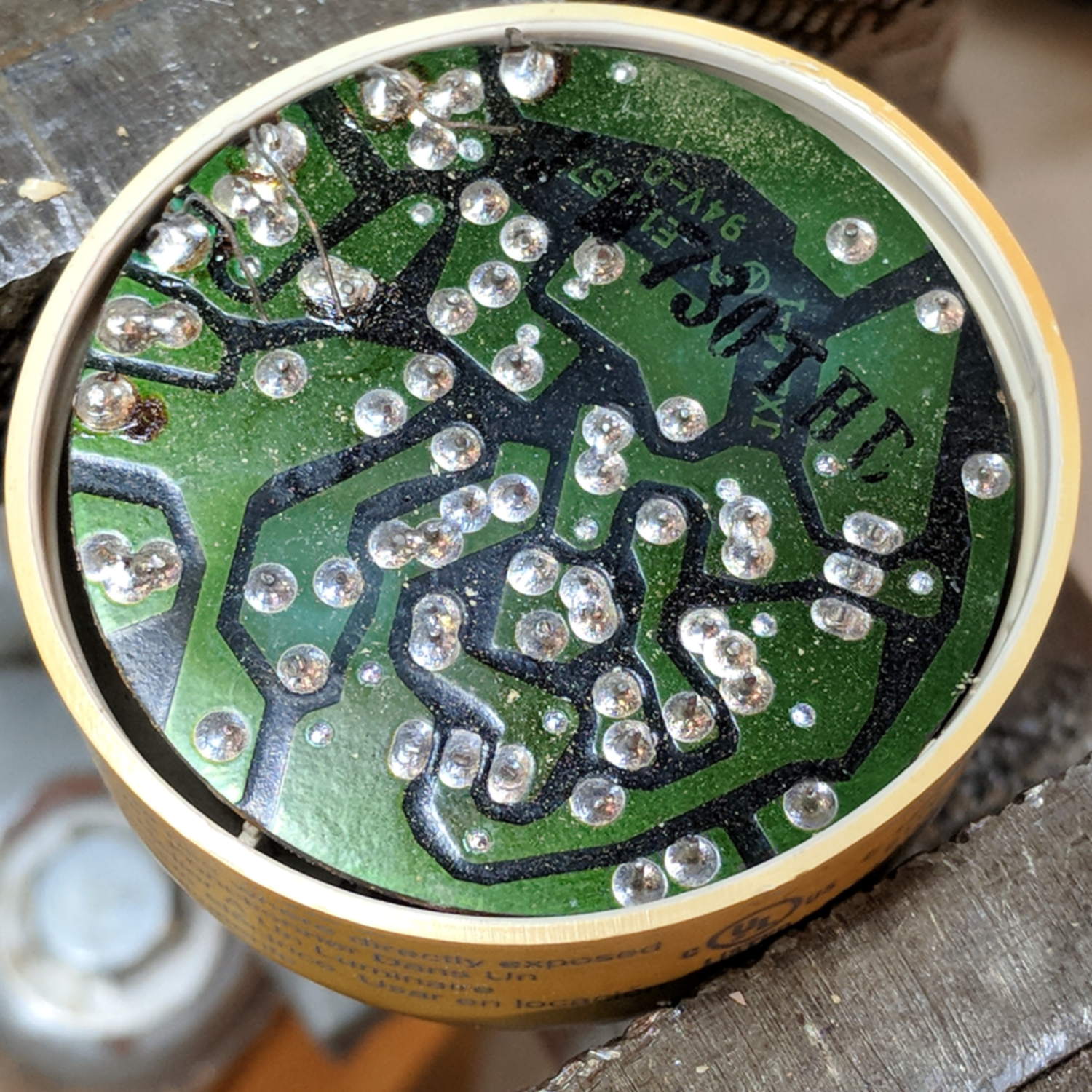
Those wires pass through notches on the edge of the PCB, bend around the board, pass through vias, and get soldered to pads. The solder side faces the tube, with all the components nestled into the base toward the screw terminals:
Failed CFL – PCB solder side faces upward
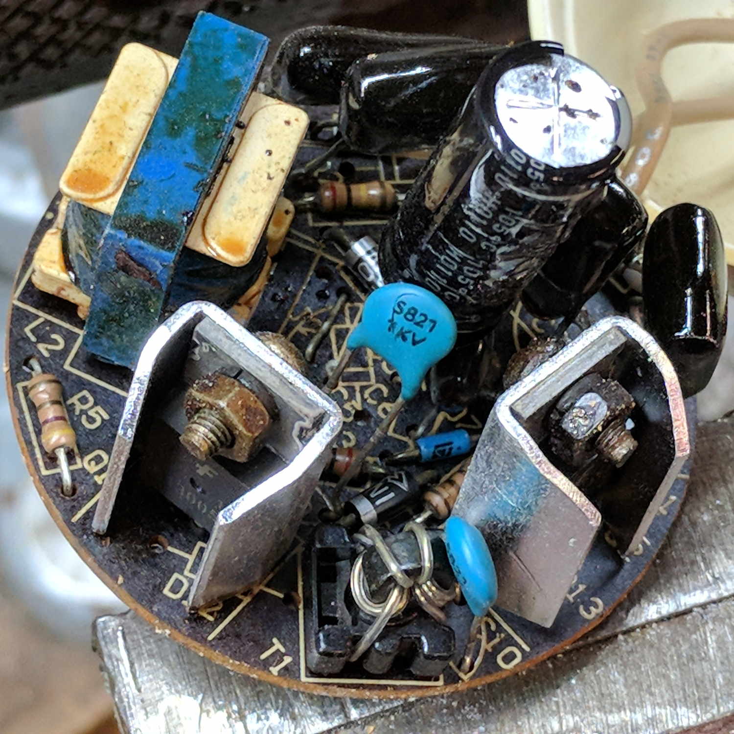
The component side sports a surprising number of parts:
Failed CFL – PCB components – 2
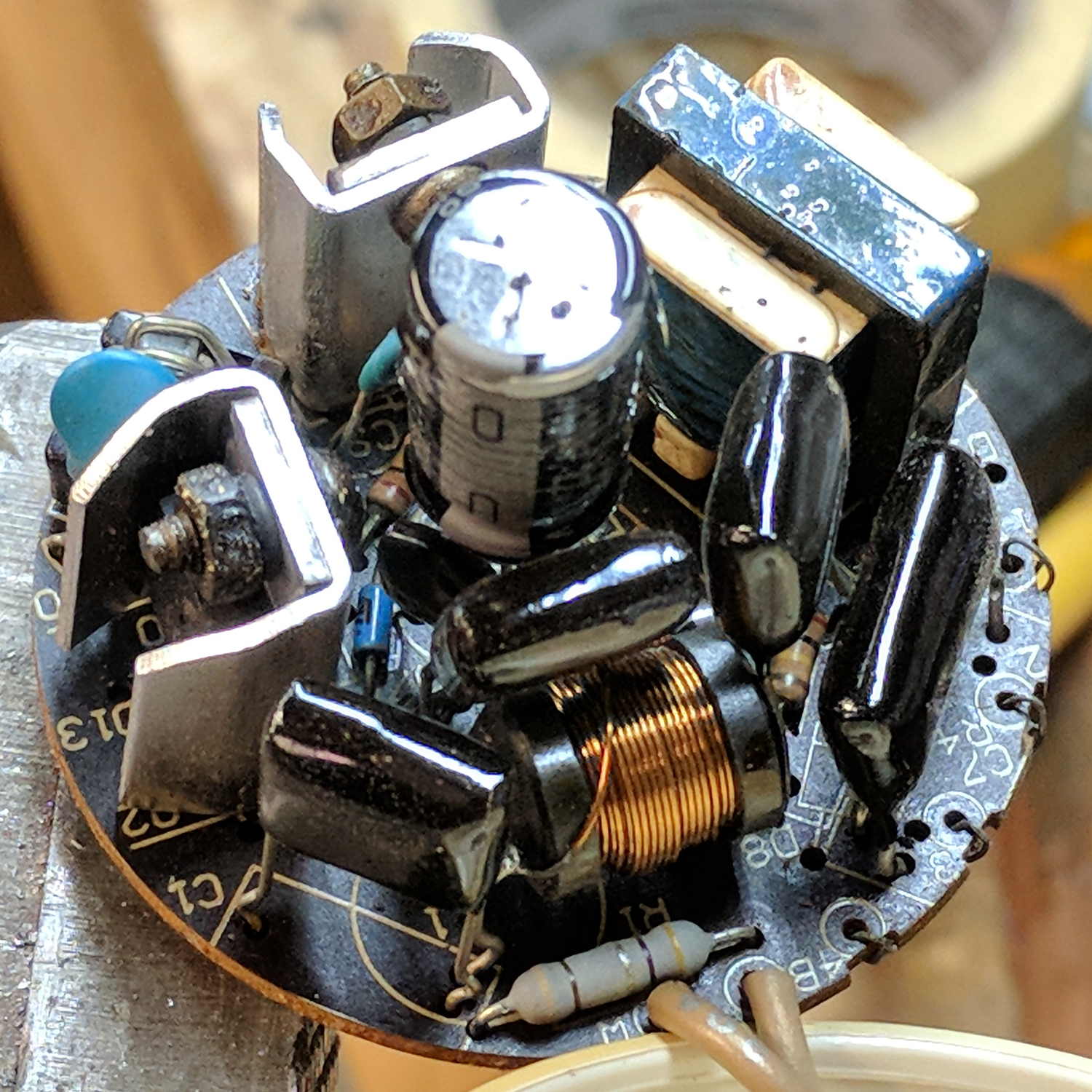
A view from the other direction, where you can see the tube wires curling around the edge:
Failed CFL – PCB components – 1
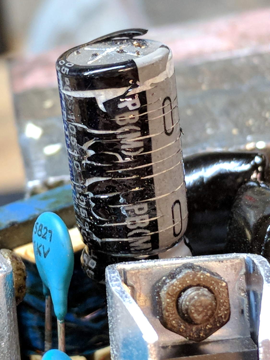
I generally harvest inductors & suchlike, but it got really really hot in there and, methinks, cooked the life out of the parts:
Failed CFL – overheated capacitor
The PCB date code stamp could be “730”, suggesting either 1997 or 2007. In any event, it’s been a while.
I hope LED bulbs outlast these things, but I have my doubts …
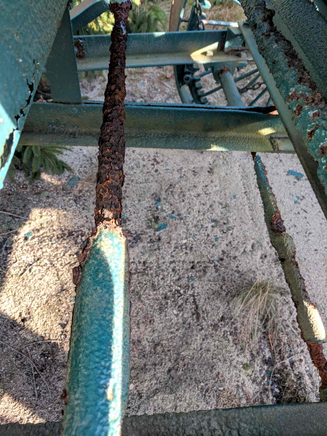
Admittedly, it’s been sitting untended for many years, but the worst corrosion formed along the midline of the machine, eating the conveyor housing, drive shafts, and support struts.
I managed to go all this time without realizing cranberry plants are evergreens.
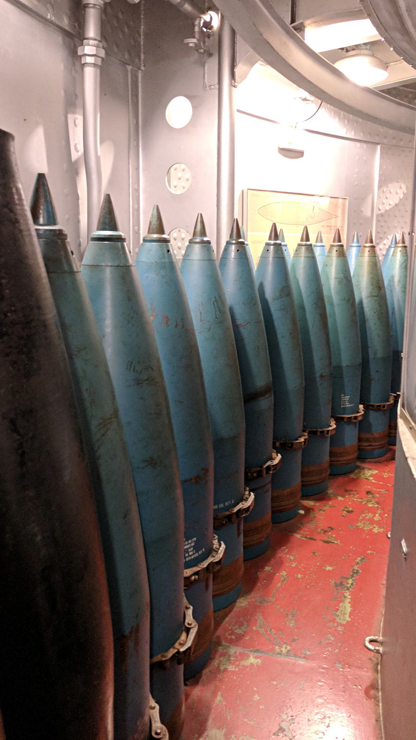
We explored the interior for several hours, all the way to the lower Turret 2 barbette:
USS Massachusetts BB-59 – Turret 2 Lower Barbette 16 inch Shell Storage
Each 16 inch projectile weighs 2700 pounds, with 800 shells distributed around three turrets. Looking at the drawings doesn’t make up for seeing the machinery.
The Massachusetts did shore bombardment during the Solomon Island campaign, where my father was assigned to guard a forward observer targeting Japanese redoubts and caves. He said the first rounds went over the far horizon, the second group landed short in the valley, and, from then on, the observer called out coordinates, walked the impact points down the valley, and wiped out each target in succession. BB-59 may not have been on the other end of those trajectories, but he said the Navy saved them plenty of trouble and inconvenience …