Mary’s folks asked me to figure out why the carousel on their Kodak 750H projector no longer turned. Some initial poking around suggested a problem with the solenoid, which only clunked when the projector was upside-down on the desk. I thought it might just have gummed up after all those years, but disassembling the thing (per the Service Manual and the usual Youtube videos) produced the root cause:
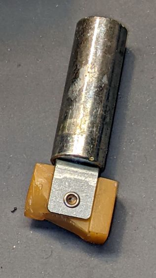
That explained the yellowish plastic fragments rattling around inside.
As predicted, it’s impossible to remove the solenoid without breaking the equally brittle focus gear in the process:
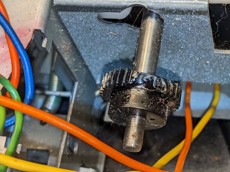
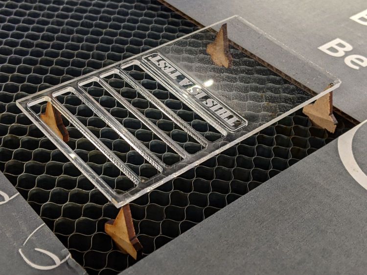
This is a sufficiently common projector to make repair parts cheap and readily available, at least for now.
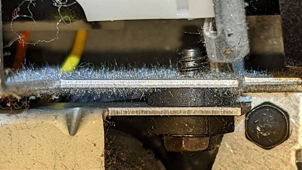
Some of the interior sheet metal has a dark surface, likely heavy tin plating, covered with a thick coat of whiskers:
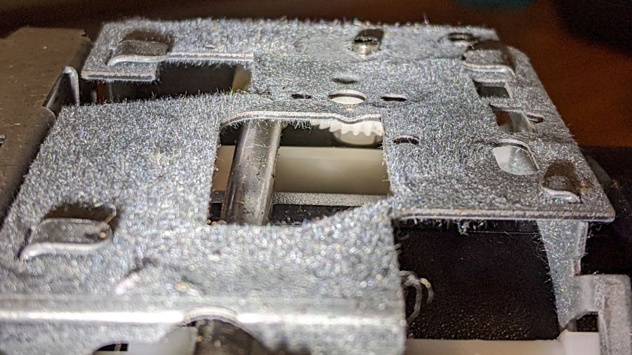


Touching a whiskered surface with masking tape captures the culprits, whereupon zooming the microscope and camera all the way in makes them just barely visible: they’re a few millimeters long and a few atoms wide:
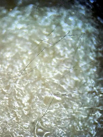
I have surely contaminated the entire Basement Laboratory with tin whiskers. Makes me itchy just thinking about them …


