Ed Nisley's Blog: Shop notes, electronics, firmware, machinery, 3D printing, laser cuttery, and curiosities. Contents: 100% human thinking, 0% AI slop.
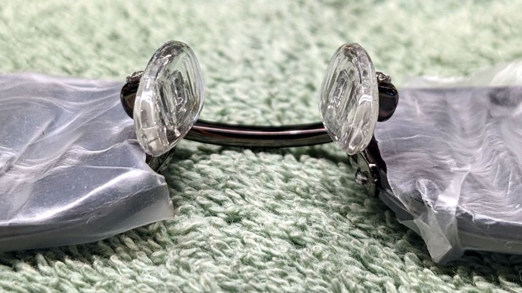
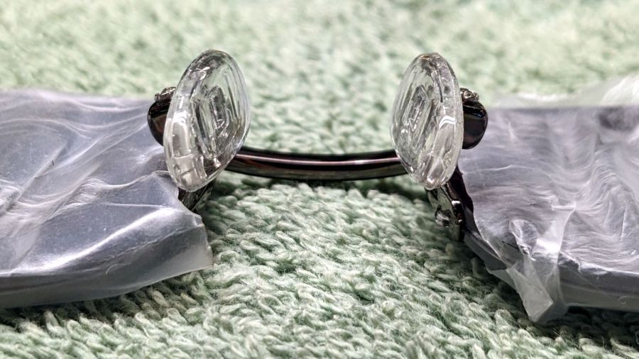
I suppose this is a consequence of being able to get two eyeglasses + two sunglasses in three different frame styles and two different prescriptions, each with progressive lenses and antireflective coating, for about $350 delivered halfway around the planet.
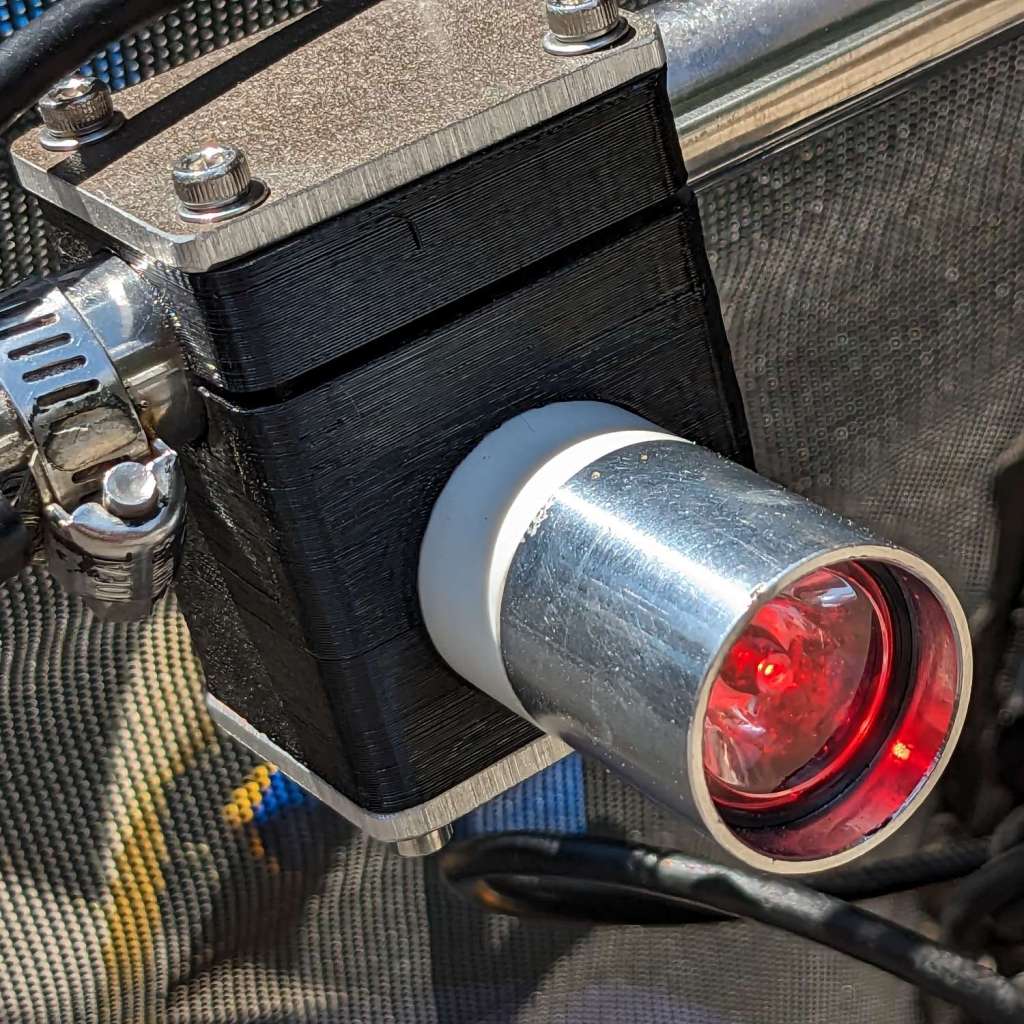
The running lights have the same general structure as before and fit into the same front and rear holders:
Tour Easy Running Light – rear installed
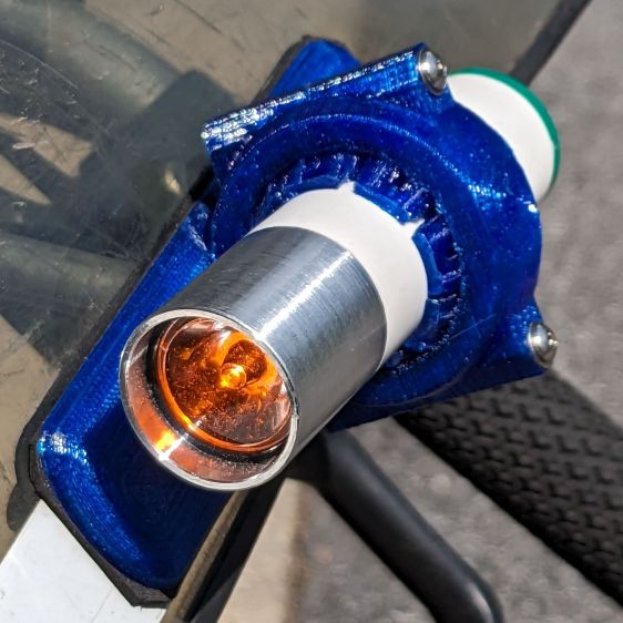
I made the recess slightly deeper to provide a bit more protection to the lens:
Tour Easy Running Light – front installed
The lenses have a 10° beam angle, so a few more millimeters of sidewall doesn’t intercept much light.
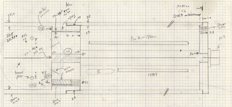
The layout doodle grew a few more notes:
Tour Easy running light – housing dimensions
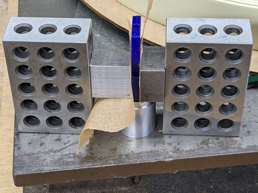
I had the good idea of boring the tube, knurling the rod, then epoxying the two together beforecutting the rod:
Tour Easy Running Light – heatsink curing
Which let the lathe hold them in perfect alignment during curing:
Tour Easy Running Light – heatsink plug alignment
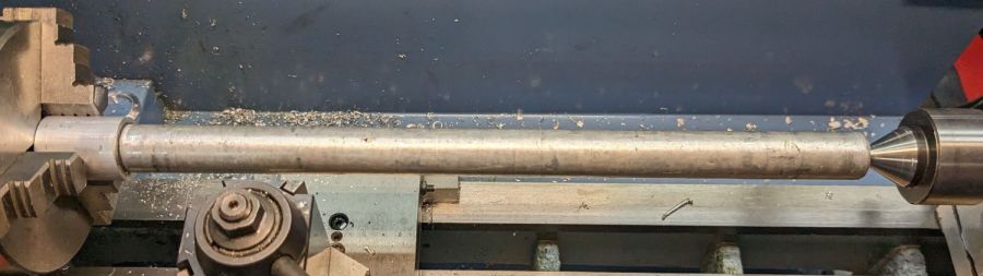
The rod fits through the lathe spindle and I intended to use it as an arbor while turning the tube exterior, then cut the finished heatsink off flush.
Which really good idea lasted until the next morning, when I looked at the setup and immediately cut the rod flush with the tube. Because reasons, perhaps excess blood in my caffeine stream.
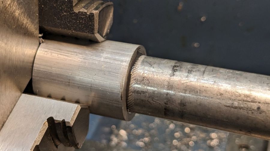
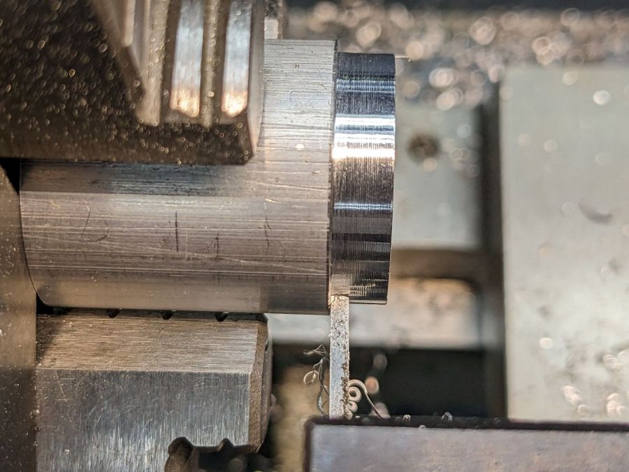
So I had to finish the heatsink on hard mode right up against the chuck:
Tour Easy Running Light – turning heatsink rebate
Flipping it around and gripping that little rebate to skim the OD down to 25 mm seemed fraught with peril, so I stabilized the open end with a chuck and plenty of oil; the live center was just too big around for the job.
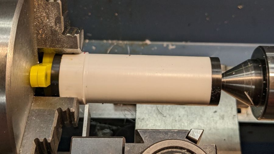
After boring the PVC pipe to 23 mm ID, I made a pair of Delrin fixtures to simplify turning the exterior to 25 mm before parting it off:
Tour Easy Running Light – turning body OD
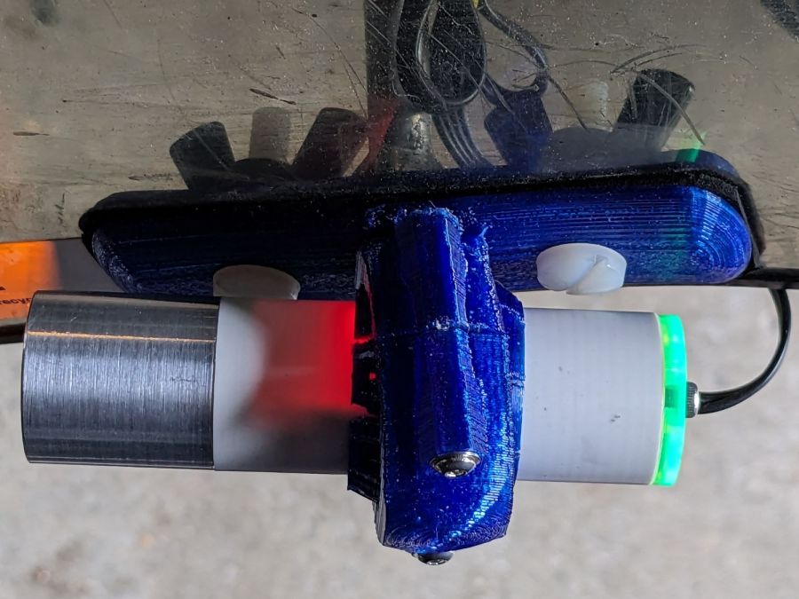
The PVC is so thin the Arduino’s LEDs shine right through:
Tour Easy Running Light – installed top view
The radioactive green endcap is ordinary laser-cut fluorescent edge-lit acrylic with sunlight through the garage door on the left. I used red acrylic for the taillight to encourage their separate identities.
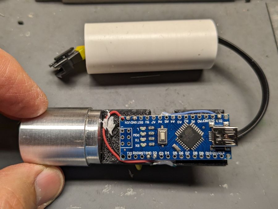
The knockoff Arduino Nano fits on one side of the support plate:
Tour Easy Running Light – Arduino view
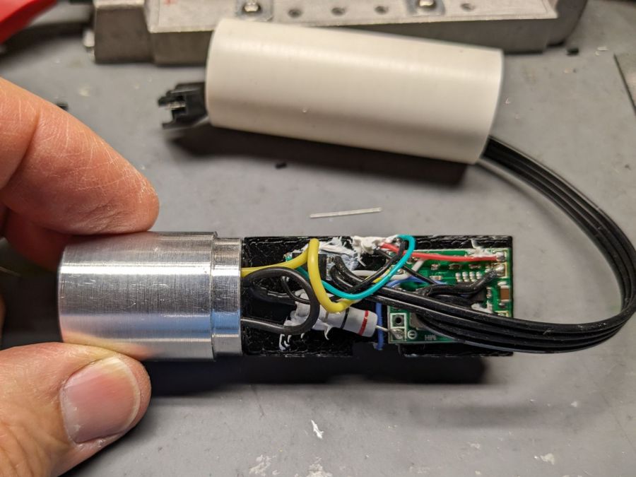
And the current regulator on the other:
Tour Easy Running Light – current regulator
Because these run from a dedicated 6.3 V step-down regulator, rather than the Bafang controller’s headlight output, the 2.0 Ω sense resistor sets the LED current to 0.8 V / 2.0 Ω = 400 mA, which is pretty close to the LED 1 W spec.
The white blob at the end of the two ribbon cable wires is the optoisolator pulling down a pin when the LIGHT signal is active, telling the firmware to stop the normal blink pattern and just turn the LED on all the time. This will come in handy if I ever do any night riding.
The LED is epoxied to the aluminum shell (with metal-filled JB Weld) and the whole affair never gets more than comfortably warm even with the LED running constantly.
I think they came out All Good™, despite various blunders along the way.
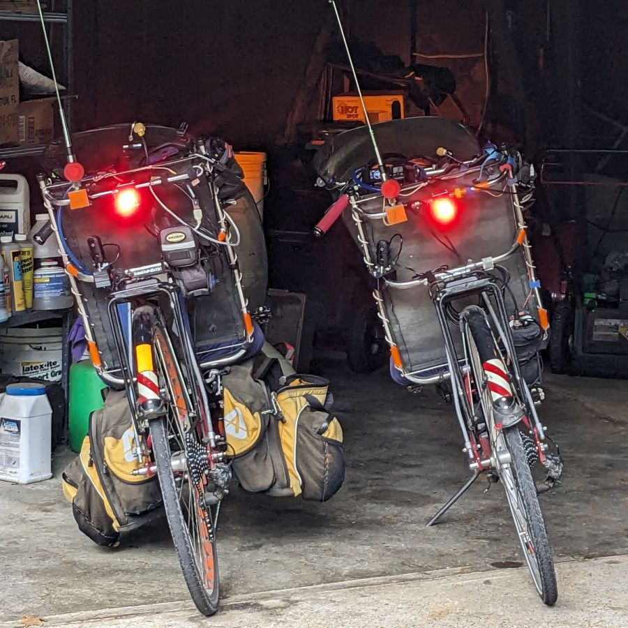
Having just finished another set of daytime running lights, we once again have a matched pair of Tour Easy recumbents:
Tour Easy Running Light – two tail lights
Although both ‘bents have Bafang 750 W motors with 48 V lithium batteries and both motor controllers have “light” outputs, they are different.
The controller on Mary’s bike (on the right) has a 6.3 V output that goes active when you press the 500C display’s + button for a few seconds. Those running lights simply use the light output for power, with a bit of tweakage to keep their current draw within the 500 mA limit.
The controller on my bike (on the left) has a 12 V output that goes active when I press-and-hold the headlight button on the DPC-18 display’s pad. Unlike the 500C, however, the DPC-18 dims its display when the lights are on, rendering it completely illegible in sunlight.
Because the running lights must operate with the headlight output inactive, a buck converter from a randomly named Amazon seller steps the 48 V battery down to 6.3 V. Note that the usual buck converters have a 36 V upper limit, so you want one with an LM2596HV regulator.
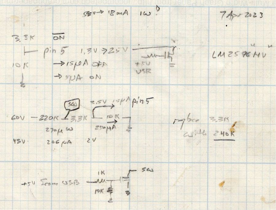
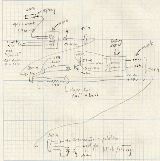
Because the regulator should be turned off when the motor controller is off, it must have a control input to enable / disable it; even if the regulator has the input pin, most boards don’t bring it out to a pad. The PCB I used has a SW input that must be low to enable the regulator, as shown in the middle doodle amid these scratches:
Tour Easy running light – buck converter SW control doodles
The SW pad on the PCB drives a voltage divider made from a 3.3 kΩ and a 10 kΩ resistor, with the regulator’s control (pin 5) looking at the junction. Running the numbers suggested a 220 kΩ resistor from the battery + terminal would provide enough current to hold the pin high, while not drawing more than a few hundred microamps, and a transistor could pull it low to turn the regulator on.
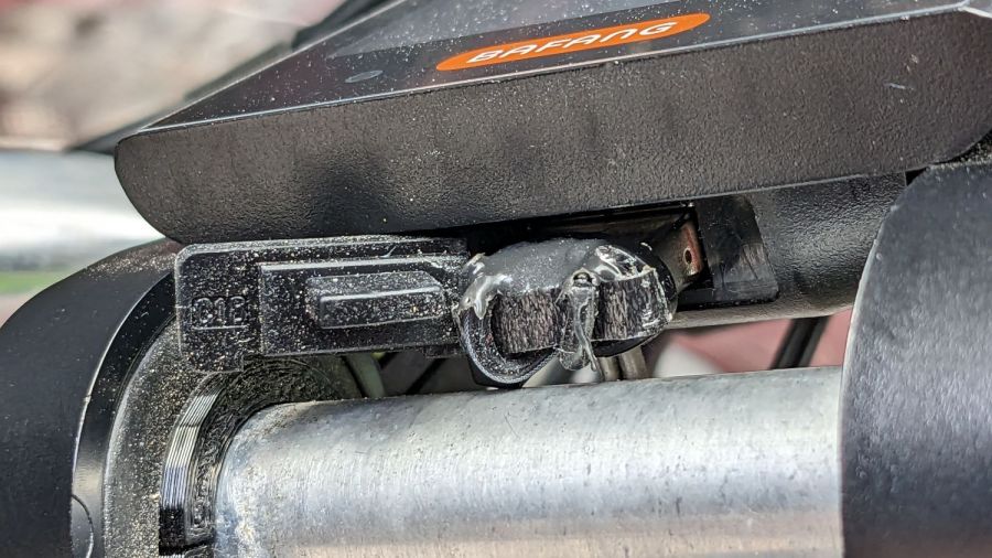
The DPC-18 display has a USB port to charge your phone on the go, so I hijacked that to get +5 V when the controller is turned on:
Tour Easy Running Light – Bafang DPC-18 USB plug
It’s a cut-down USB breakout board with two 24 AWG wires stripped from a ribbon cable soldered in place and coated with epoxy. The silicone port cover sticks out on the left; I eventually jammed it under the display panel in lieu of cutting it off.
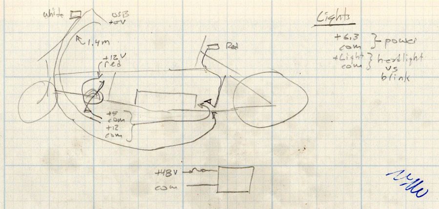
Although I want the running lights on whenever the controller is on, It Would Be Nice™ to have a steady headlight / taillight in the unlikely event I ever ride after dark. With that in mind, the USB power pair joins another pair from the motor controller’s LIGHT connector (via a red 2-pin Juliet plug), so the firmware can tell when the headlights should be on, and the resulting 4-wire ribbon cable wanders off to the battery mounting plate:
Tour Easy running light – wire routing doodle
The connectors along the way are 4-pin JST-SM 2.5 mm, which are most certainly not watertight. We’re fortunate in being able to not ride in the rain whenever we want, so the connectors won’t be exposed to water very often.
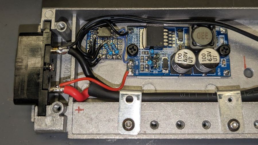
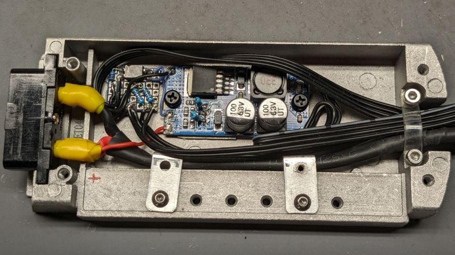
The battery mounting plate has an aluminum casting with a small compartment, probably intended for a complete e-bike controller, that just barely holds the hardware required to produce the 6.3 V supply:
Tour Easy Running Light – Bafang battery base circuitry – detail
Yes, those exposed battery terminals with soldered-on wires got a silicone tape wrap. No, there are no fuses involved. The two steel brackets holding the main power cable in place came pre-bent and pre-drilled in a random piece of scrap harvested from some dead equipment; they’re screwed into pre-tapped holes intended for the six TO-220 style power transistors of the missing motor driver.
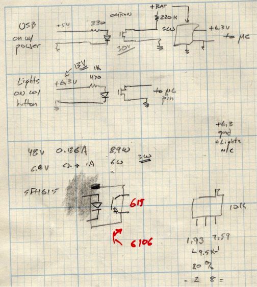
The perfboard in the upper left holds an optoisolator for the USB power → SW input and a pair of resistors for the LIGHT signal to the headlight and taillight:
Tour Easy running light – control doodles
The optoisolators come from an ancient surplus deal; the bag I thought contained unmarked SFH615 parts apparently got mixed with some unmarked SFH6106 parts with the opposite transistor pinout.
The sketched trimpot in the lower right was on the buck regulator board, where it stood just an itsy too tall to fit the space available. Given that I would never adjust it, I set it for 6.3 V, removed it, measured the resistances, substituted fixed resistors, and the board should produce 6.3-ish V forevermore.
The regulator sits atop heatsink tape on a brass sheet with more heatsink tape isolating it from the housing and two nylon screws holding the stack in place.
With the various cables soldered in place:
Tour Easy Running Light – Bafang battery base circuitry – wired
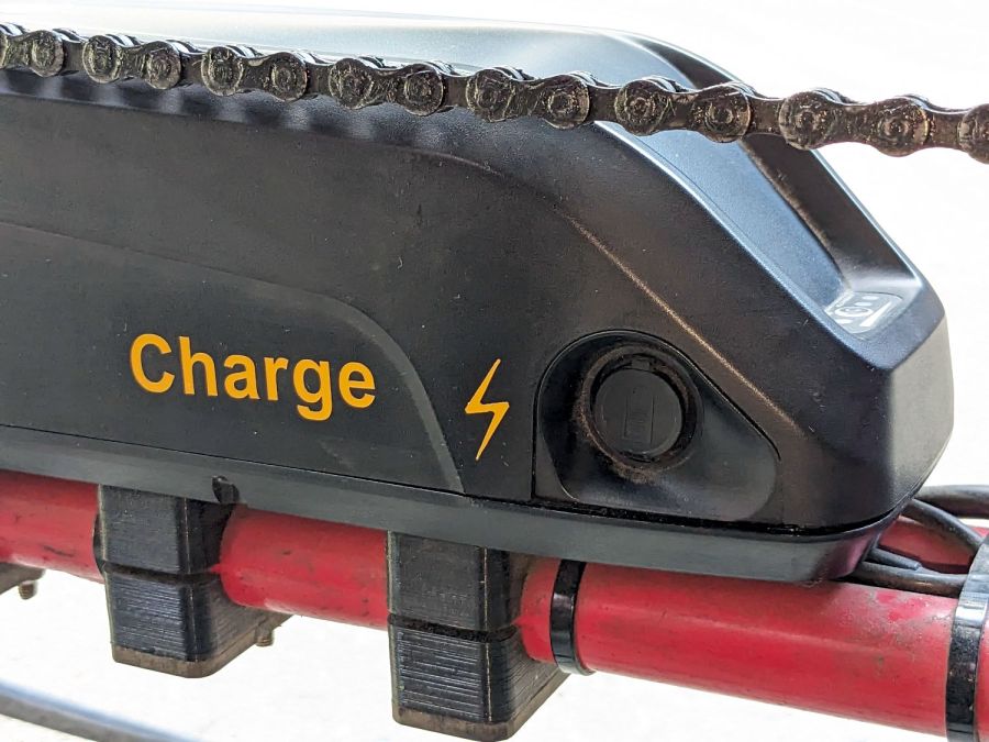
Based on Tee’s unfortunate experience, I finally got around to labeling the Bafang batteries on our Tour Easy ‘bents:
Bafang battery labeling – charge jack
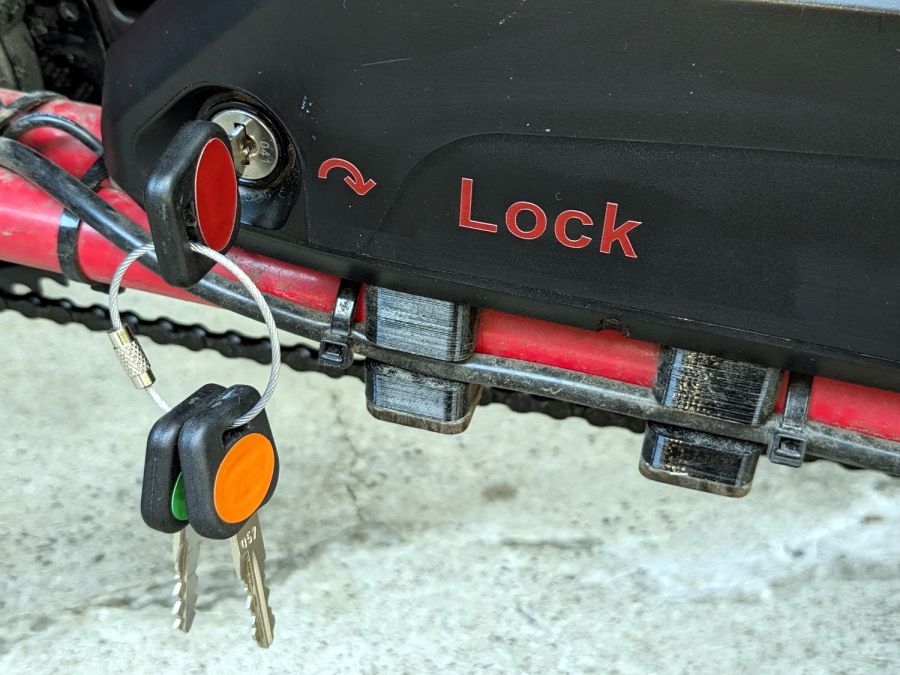
On the other side, each lock is now color-coded to its key:
Bafang battery labeling – lock and keys
It’s laser-safe polyurethane vinyl applied to the battery after vigorously wiping crud off the surface with denatured alcohol. Think of it as an outdoor testcase for PSA vinyl.
I’m sure there’s a master key out there for all e-bike locks, but we remove them so rarely the color coding should suffice.
Worst case, pick the lock with a piece of wire and a hex key.
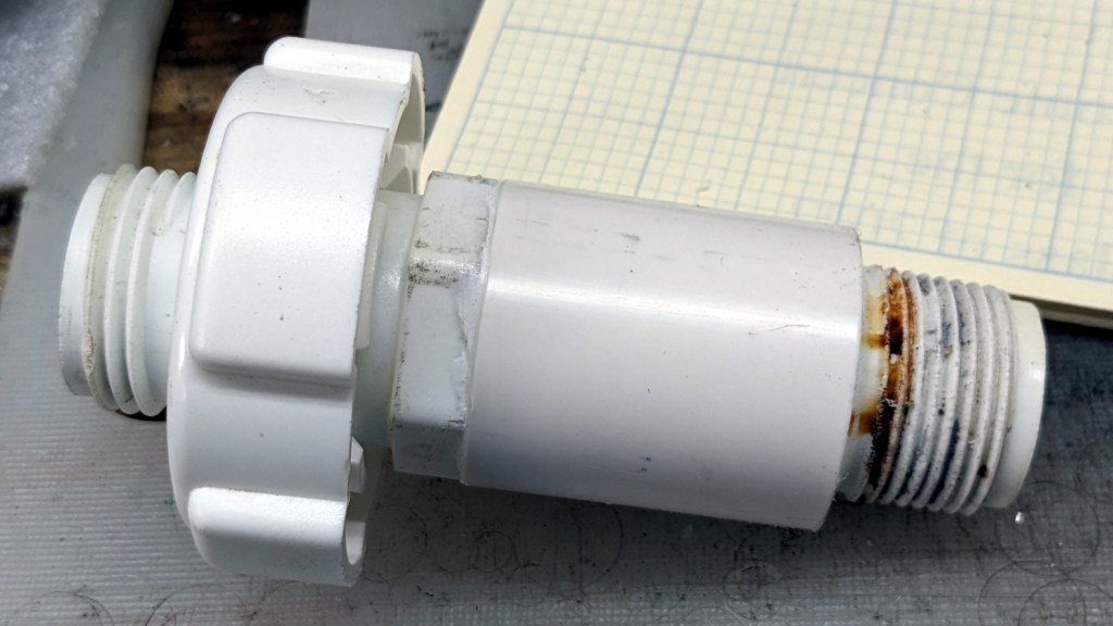
It lacks the flange required to seal the O-ring against the outside of the bin, but I can fix that:
Can-o-worms – sleeved valve
It’s a chunk of PVC pipe faced to the proper length, bored to fit the valve body, then gooped in place with acrylic caulk.
Snug the nut inside the bin and it’s all good:
Can-o-worms – new valve installed
The original valve depended on having a smooth plug turning inside the outer shell, but years of grit scarred the interface enough to produce a slow drip. It also had the annoying mis-feature of aiming the opening inward, between the bin legs, where a jug didn’t quite fit.
The water heater valve depends on compressing a smaller O-ring against a seat inside the body, which may tend to clog with crud. We added a mesh filter to hold back the worst of the gunk, so this is in the nature of an experiment using free hardware.
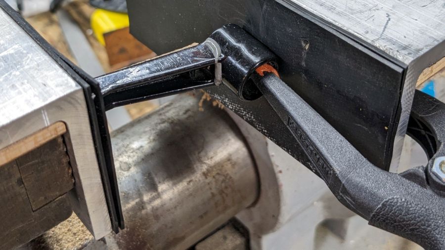
I finally managed to whack the mini-lathe’s carriage stop handle with the chuck, prompting a quick repair:
Carriage Stop – handle epoxy clamping
I probably should have epoxied a rod into the recess under the handle, seated in a drilled hole into the hub, but let’s see how long this quick-n-dirty version lasts.
While I had the hood up epoxy was curing, I lasered a block of edge-lit acrylic to replace the credit card shims:
Carriage Stop – spacer
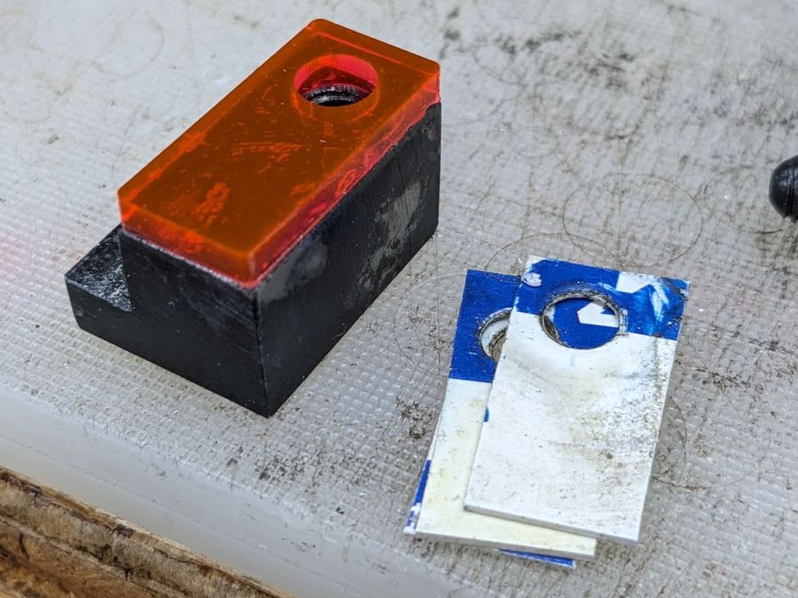
Which turned out to be one itsy too thick. Rather than sand / machine it down, the step over on the left grew a little brass shim:
Carriage Stop – spacer and shim
Both pieces depend on snippets of adhesive sheet to hold them in place, which seems reasonable because they’re always in compression. That also eliminates the hole and pin I originally thought would be necessary; living in the future is just grand.