Ed Nisley's Blog: Shop notes, electronics, firmware, machinery, 3D printing, laser cuttery, and curiosities. Contents: 100% human thinking, 0% AI slop.
The Screen Filter (DD81-02011A) in our Samsung dishwasher (DW80K7050US) turned out to have a mold defect from the factory that’s been sitting there since the previous owners had it installed back in 2018:
Samsung dishwasher screen filter – gap
The mesh apparently didn’t quite make it into the molded plastic, so that little gap has been letting debris in the wash water circulate through the spray bars and clog the orifices.
That’s a bead of EVA hot melt glue that will probably withstand the 163 °F = 73 °C “sanitize” cycle we haven’t had any occasion to use and seems no more toxic than anything else around here.
Protip: if your dishwasher has a filter, it’s likely clogged with a nasty accumulation of gunk, too …
The mounting block under the electronics box for the new UPP battery has a recess for an M5 tee nut:
UPP Battery Mount – Block 5 Show View
As with the Terry frame mounts, I glued the modified tee nut in place with JB Plastic Bonder urethane adhesive, did a test fit on the bike, discovered the whole affair had to sit about 10 mm forward, put the new frame measurement into the OpenSCAD code, and ran off a new block.
Which gave me the opportunity to perch the old block atop the bench vise with the tee nut aimed downward between the open jaws, run an M5 bolt into the nut, and give it a good thwack with a hammer:
UPP Battery Mount – M5 insert adhesive test
Although the urethane adhesive didn’t bond uniformly across the tee nut, it had enough grip to tear the PETG layers apart and pull chunks out of the block.
As with the tee nuts on the Terry bike, this one will be loaded to pull into the block, so it will never endure any force tending to pull things apart, but it’s nice to know how well JB Plastic Bonder works.
I chiseled the PETG and adhesive debris off the tee nut, cleaned it up, slathered more Bonder on the new block, and squished the nut in place. After I get the electronics box sorted out, the whole affair will never come apart again!
A wood desk chair that I’ve known since I was a pup finally got some much-needed attention, although not a restoration. By and large, I’m finally sorting out that corner of the basement and needed to put the chair’s parts back together so I can work on something else.
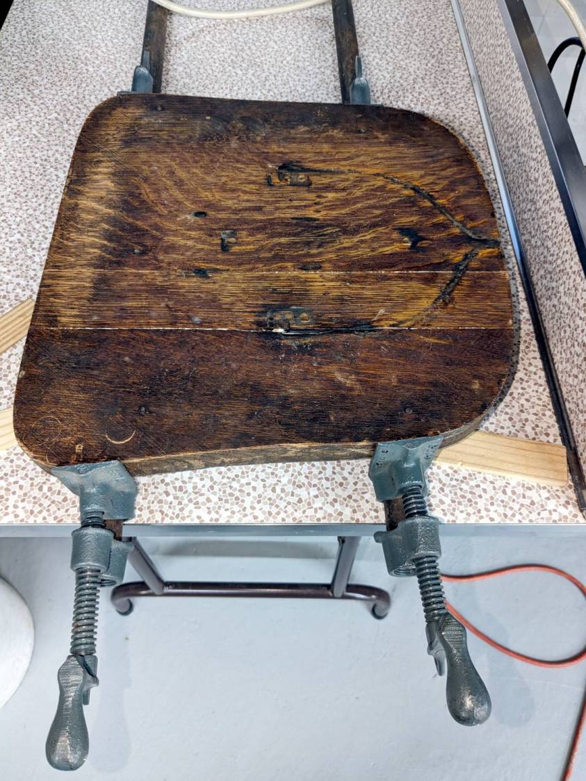
The wood seat consists of several slabs glued along keyed joints, one of which had fractured into a rough mess. Amazingly, the two sides fit perfectly together, albeit with the bottom no longer a planar surface, and glued up just like they should:
Wood desk chair – seat clamping
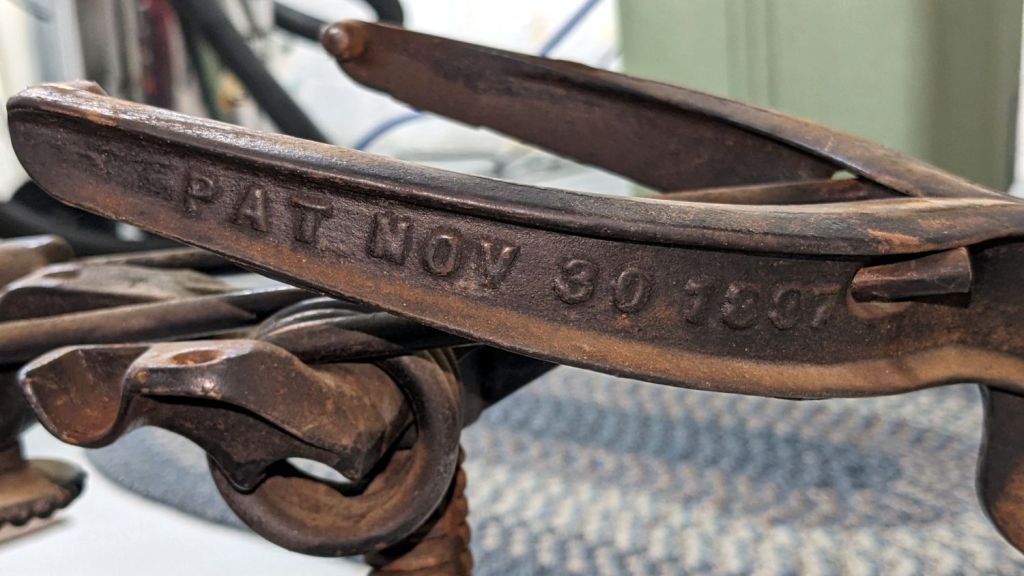
The chair isn’t up to contemporary office standards, but it has a seat elevation screw, a backrest with adjustable angle & elevation, and even a backrest tension setting:
Wood desk chair – ironwork
It was the cutting edge of desk chair technology:
Wood desk chair – patented
I vaguely recall it rolled on long-vanished steel-wheeled casters. Somewhat less long ago, one of the legs broke enough to lose its caster socket (about which, more later), so I set about yanking the three remaining sockets:
Wood desk chair – caster socket removal
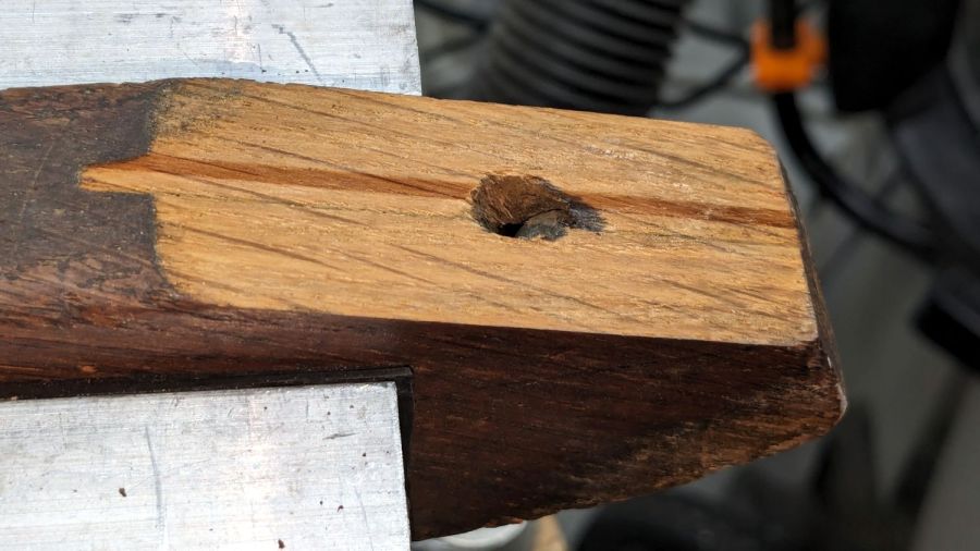
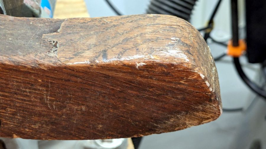
During that struggle, another leg revealed a neat woodwork joint:
Wood desk chair – leg joint
It’s easy to remove a caster socket when you can bash it from the top!
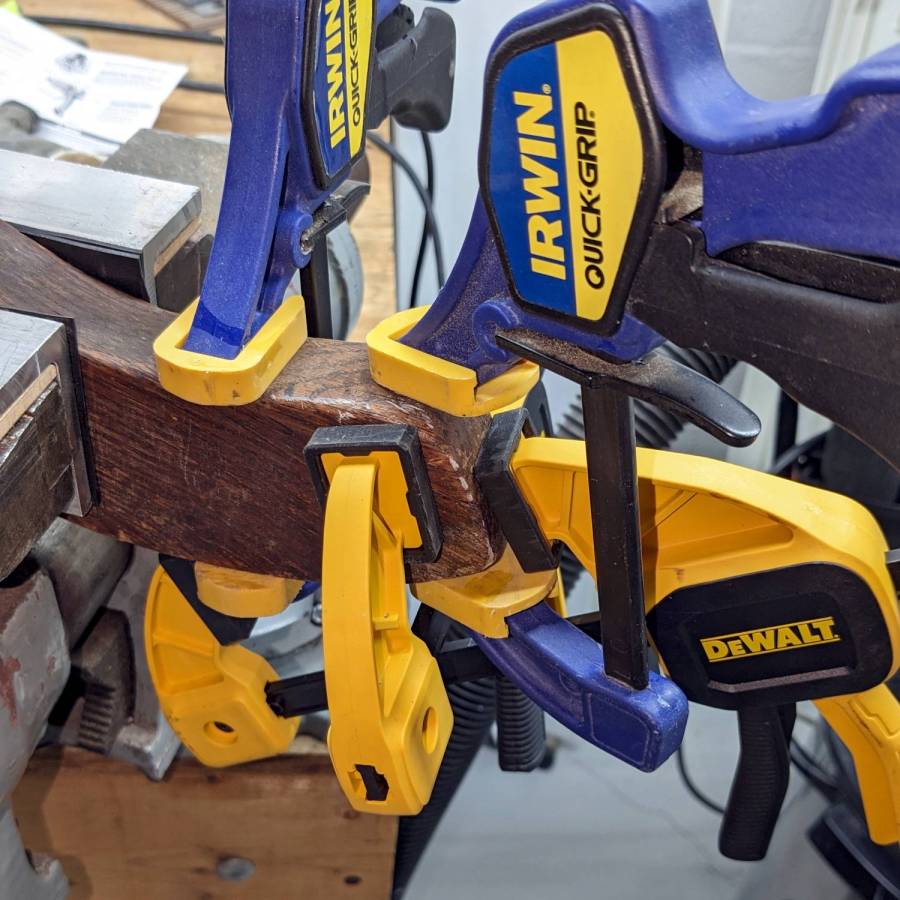
Gluing that piece back in place required Too Many Clamps™ aligning it with the leg:
Wood desk chair – leg clamping
But the end result looks pretty good:
Wood desk chair – leg glued
They did a nice job of matching the wood grain; I hadn’t noticed that joint while attacking the socket.
Pending restoring the broken leg’s socket, the soon-to-arrive new casters will clash horribly with the chair’s woodwork. At least it’ll roll again and its new plastic wheels won’t scar the floors.
While setting up to drill holes in the aluminum base for the running light buck converter, I wondered if laser-marking the spots directly from the solid model would work better than my usual fumbling around.
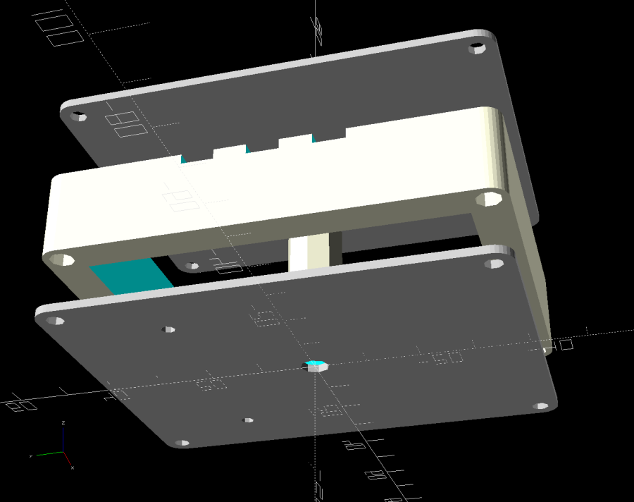
The solid model:
Running Light – power box – bottom view
Export projections of the pieces from OpenSCAD as an SVG file:
Running Light – power box – Projection view
Import into LightBurn, set up for a very fast, very light cut and Fire The Laser:
Laser-marked hole spots – masking tape
That’s in ordinary masking tape on a hard-anodized sheet of aluminum from the pile, which looked better than I expected.
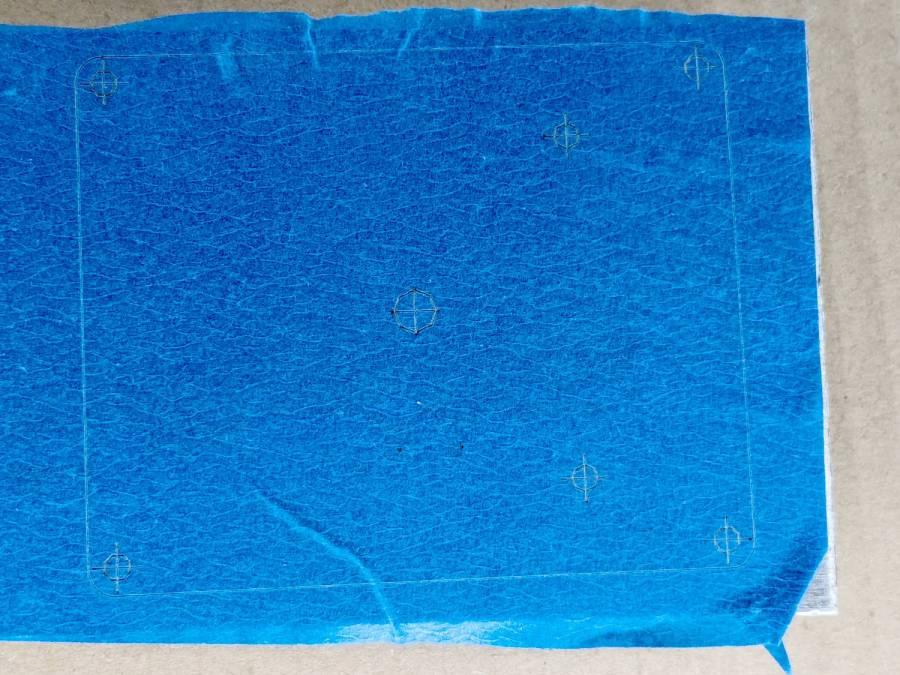
The same aluminum covered with blue tape:
Laser-marked hole spots – blue tape – hard anodize
Which looks much better in person than it does in the photo.
On a soft aluminum sheet from the Basement Warehouse Zone:
Laser-marked hole spots – blue tape – sheet aluminum
The dark outline is a comfort mark hand-drawn around a chipboard test piece to verify the layout fit between random holes drilled in the sheet during its previous life.
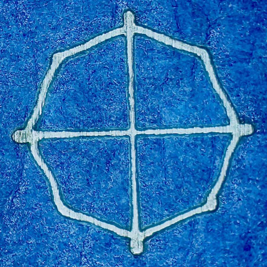
A closer look at a corner hole:
Laser-marked hole spots – blue tape – hard anodize – detail 1
And the center hole:
Laser-marked hole spots – blue tape – hard anodize – detail 2
The holes appeared in the right places after center-punching by eye, but the fragility of those four little tape leaves around the center point must be experienced to be believed.
And, yes, those are deliberately low-polygon approximations to a circle, because I’m a low-poly kind of guy.
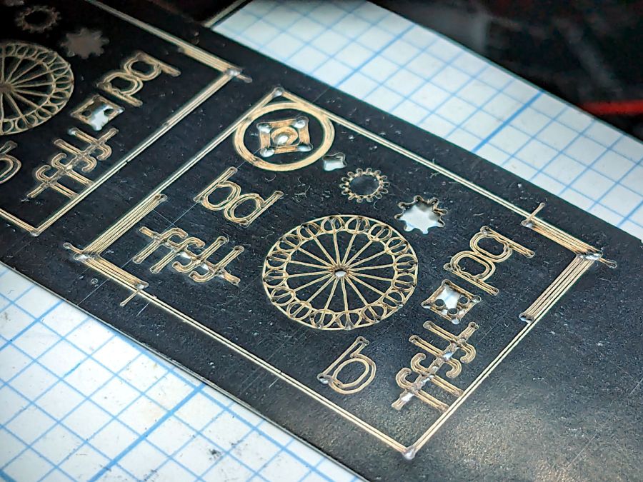
That’s the standard backlash test pattern shrunken down to a little over an inch wide, with the laser power reduced to the bare minimum. Despite that, the numerous holes show where the pattern concentrates enough energy to vaporize the paper.
The “paper” seems to be laminated between two black plastic sheets that smell terrible when engraved, so they’re probably some form of acrylic. The Amazon product description is, despite all the verbiage- remarkably uncommunicative of the actual materials involved.
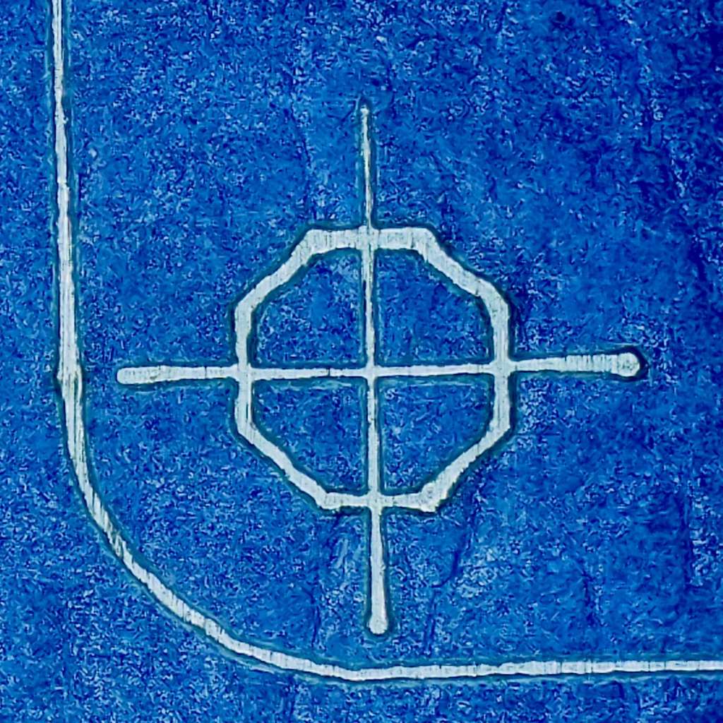
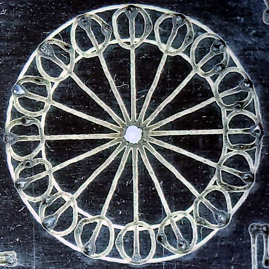
The circular pattern is 10 mm diameter on the outside:
Laser test paper – miniature pattern detail
Those should be circles around the perimeter, but their distortion shows what happens when you try to move a hulking CO₂ laser head around a 1.5 mm diameter circle at 400 mm/s. Of course, the actual speed is nowhere near that fast along such tiny vectors.
The traces are about 0.2 mm wide, with obvious scorches where the beam starts and stops, which agrees reasonably well with previousmeasurements.
All in all, both the paper and the laser pattern look better than I expected, particularly as the results indicate the machine has no measurable backlash at all.
The top profile fits snugly into the battery mounting plate, with clearance on the sides for the latches:
UPP Battery Mount – trial fit
However, I had enough trouble measuring those recesses that I broke down and added a projection() view to the OpenSCAD code:
UPP Battery Mount – profile
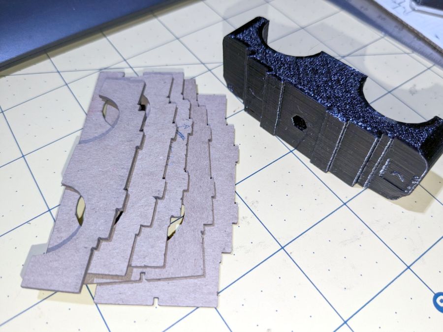
Exporting that as an SVG image and importing it into LightBurn let me cut it out of chipboard:
UPP Battery Mount – laser cut profiles
Obviously, it took several iterations to fit the top profile to the baseplate, particularly after finding slightly different measurements at each block position. On the other paw, laser cutting the profiles proceeded much more quickly than 3D printing just a few millimeters of the block, so it was a net win.
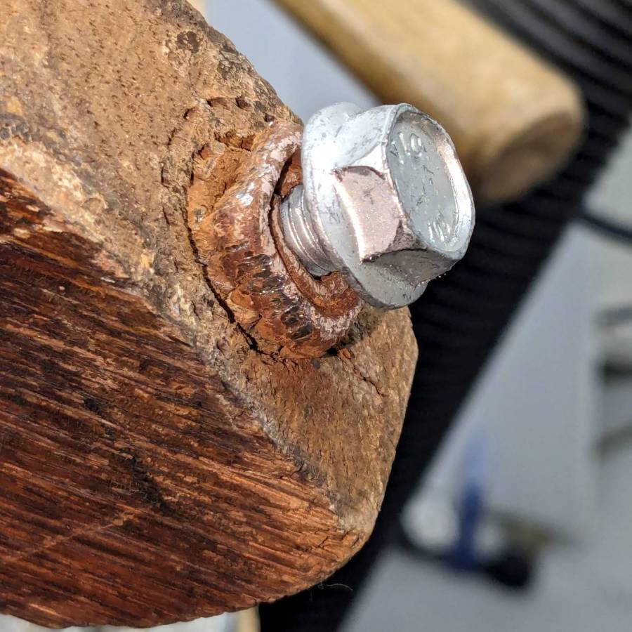
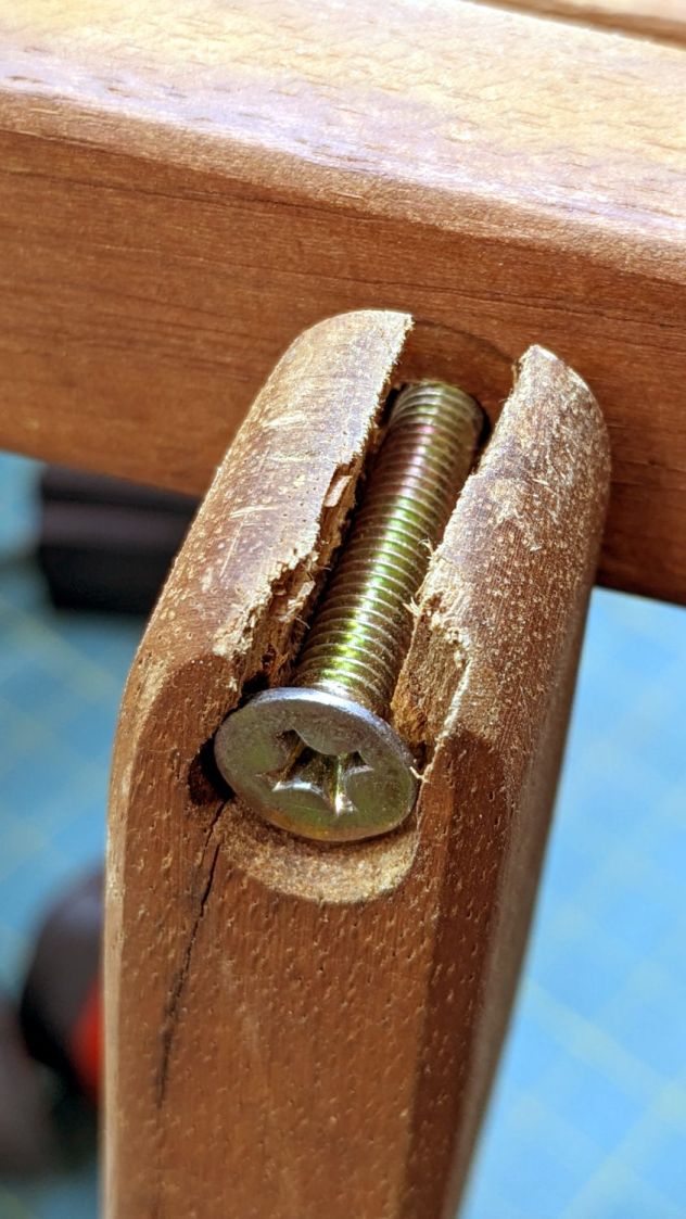
One of the folding wood chairs that Came With The House™ had a loose arm that turned out to be due to a missing chunk of wood:
Wood chair arm – as found
The obvious lay of the grain shows why it failed like that, surely hastened by the crack below the screw.
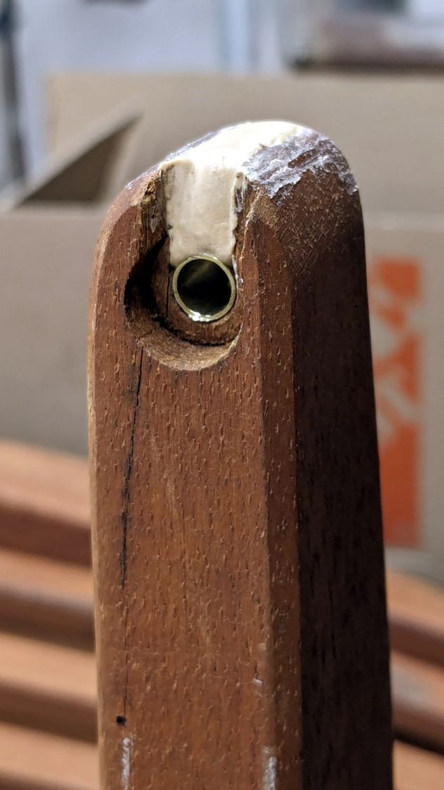
So I cut a snippet of brass tubing that, mirabile dictu, fit both the hole and the M6 screw, mixed up some wood epoxy and buttered it up:
Wood chair arm – brass tube epoxy fill
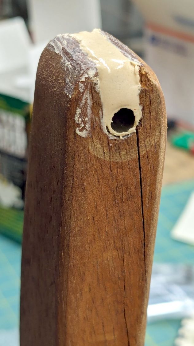
The crack extended entirely through the arm and was more extensive that seemed reasonable to expect the epoxy to handle on its own:
Wood chair arm – splits
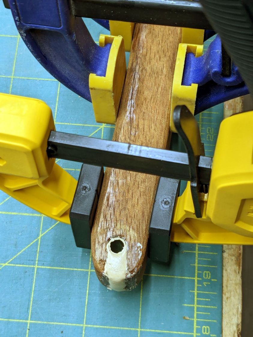
So I slobberedsoaked saturated the cracks with wood hardener and clamped them shut:
Wood chair arm – clamping
The hardener is intended to solidify rotted wood, but it makes a reasonable adhesive and, being much more liquid than ordinary wood glues, seemed like it would penetrate further into the cracks than anything else on hand. We shall see how this works out.
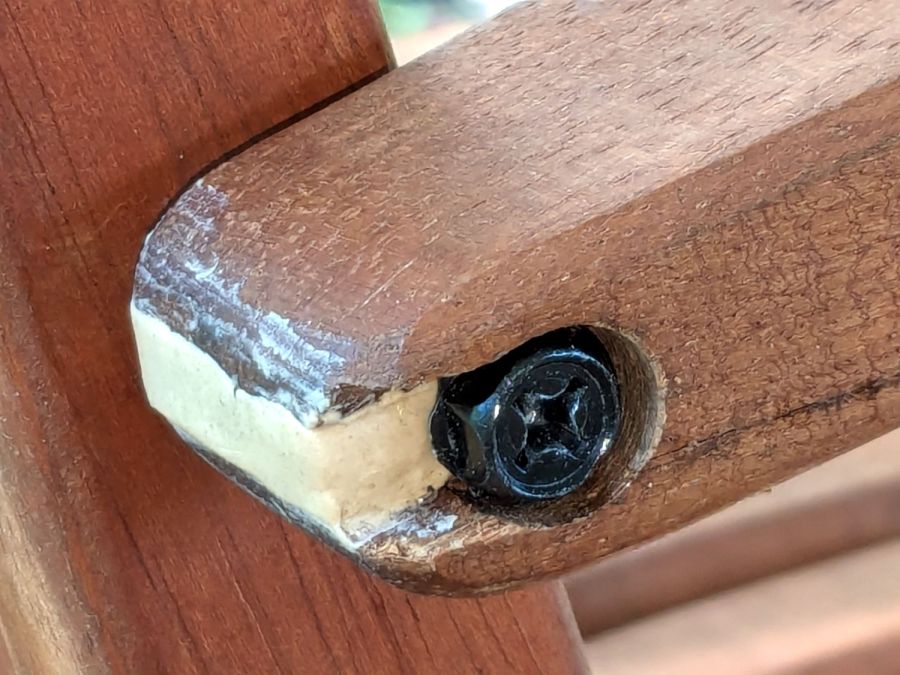
Rummaging in the Drawer o’ M6 Screws produced a better match to the brass tube than the original flat head screw:
Wood chair arm – repaired
It screws into a fancy tee nut in the upright chair rail, where a dot of thread locker should hold it forevermore.
I hit the exposed end with some sandpaper to smooth off the last of those smears and, after a few years, it’ll probably look like it grew there.