Continuing the theme of slot resizing & overall scaling:
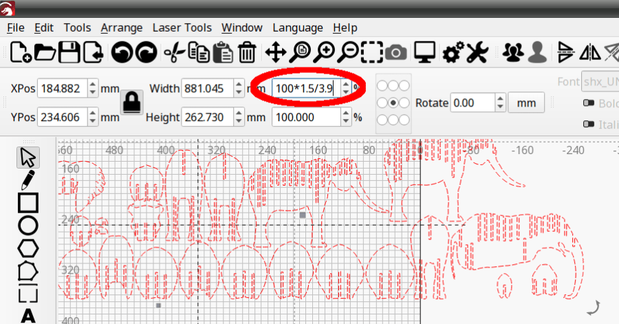
The original model has 3.0 mm slots and arrived in CorelDraw format requiring a bank shot off InkScape to create an SVG file suitable for LightBurn. After the usual cleanup & optimization, I applied global rescaling to match the available material.
The smallest beetles use 1.9 mm chipboard:
Everything is held together by ordinary wood glue, squeezed together for a few moments until the two parts no longer slide around.
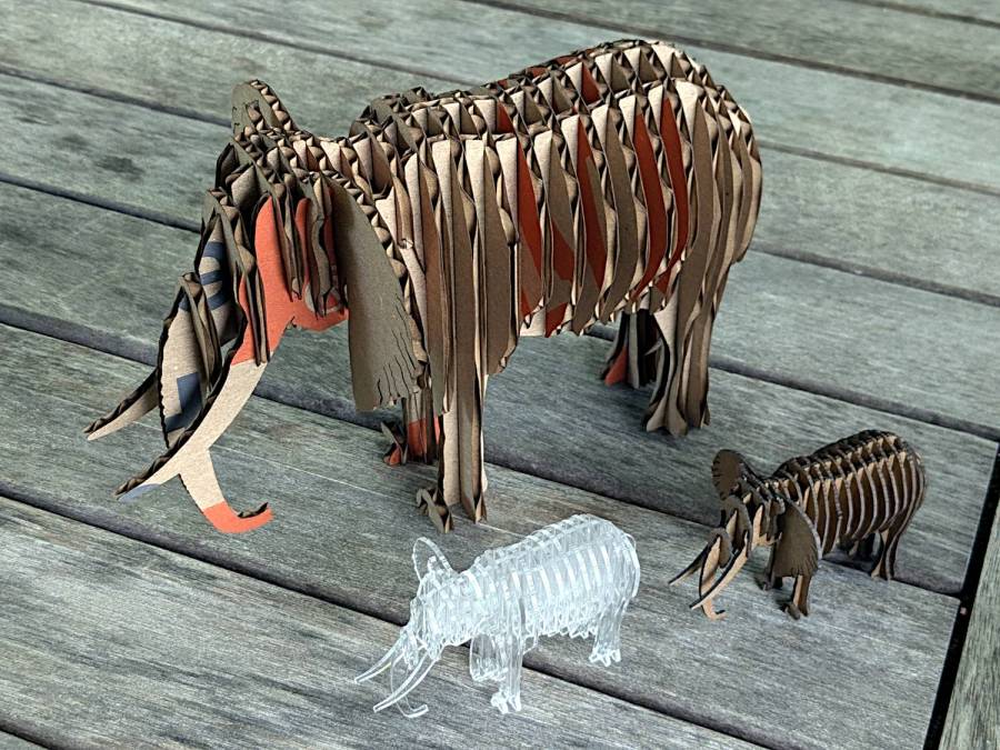
One layer of 3.9 mm corrugated cardboard:
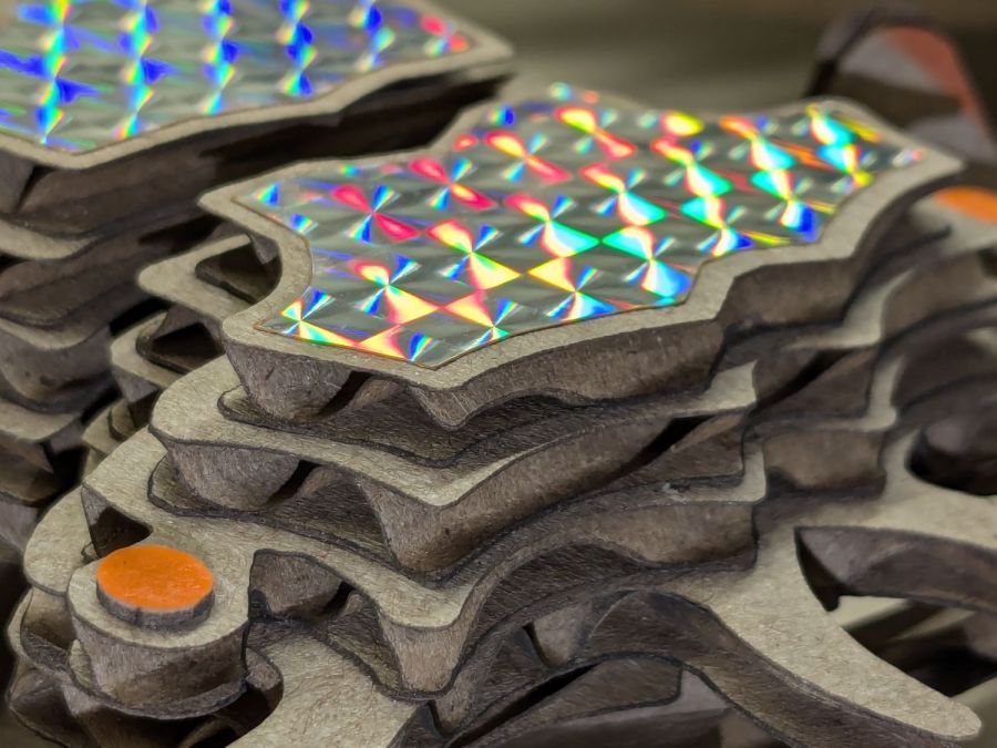
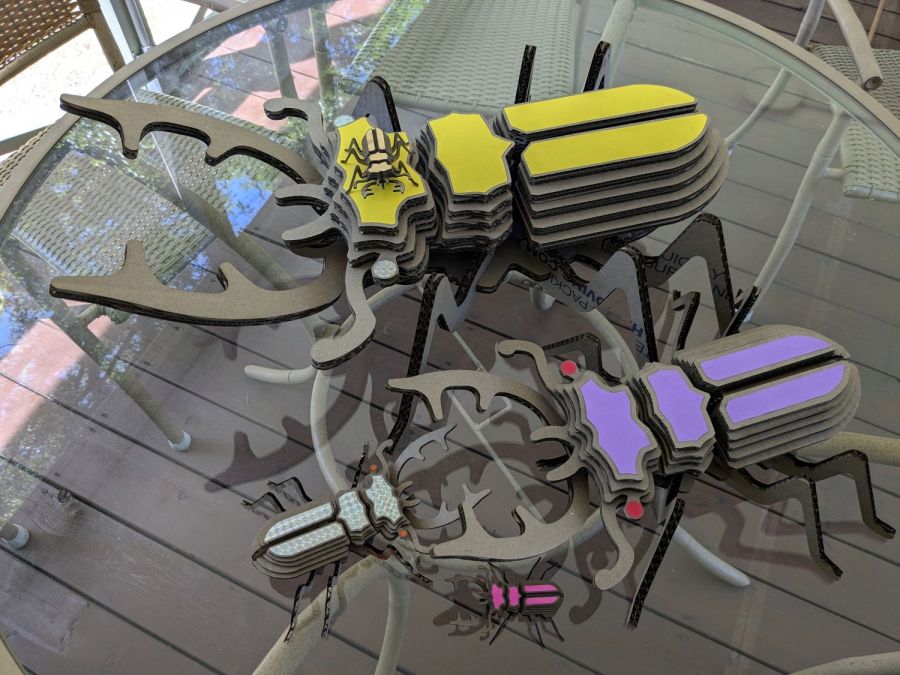
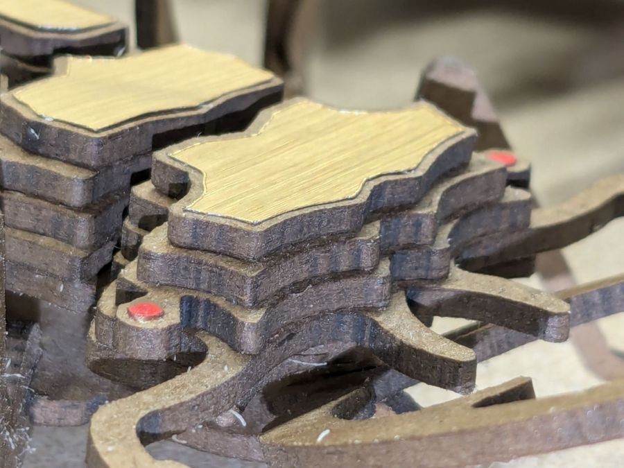
The fancy gold & hologram decorations come from what’s surely non-laser-safe PSA vinyl sheets, cut by offsetting the top layer shapes inward a reasonable amount. The eyes come from random colored paper or painted chipboard.
Two layers of cardboard add up to 8 mm:
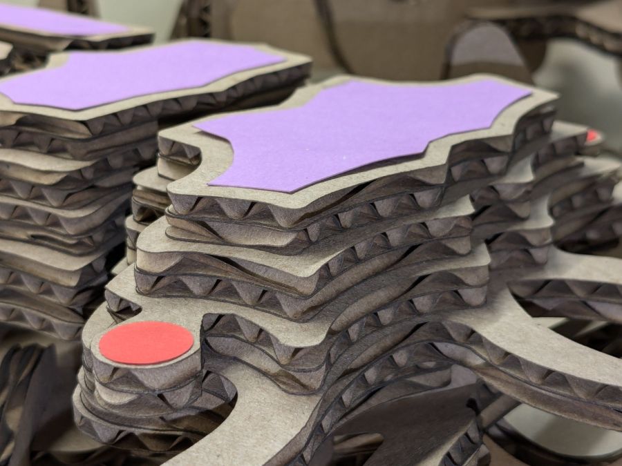
That’s purple paper left over from the layered paper quilt blocks and, obviously, my glue stick hand is weak.
Three layers of cardboard makes each part half an inch thick:

That bad boy needs black stripes on yellow in the universal “Fear me! I am a seriously dangerous creature!” danger marking.
The layers are laid out with crossed corrugations to make the part less bendy, which is more necessary for the relatively slender legs.
It’s two feet long and chewed up the better part of two Home Depot Extra Large moving boxes:
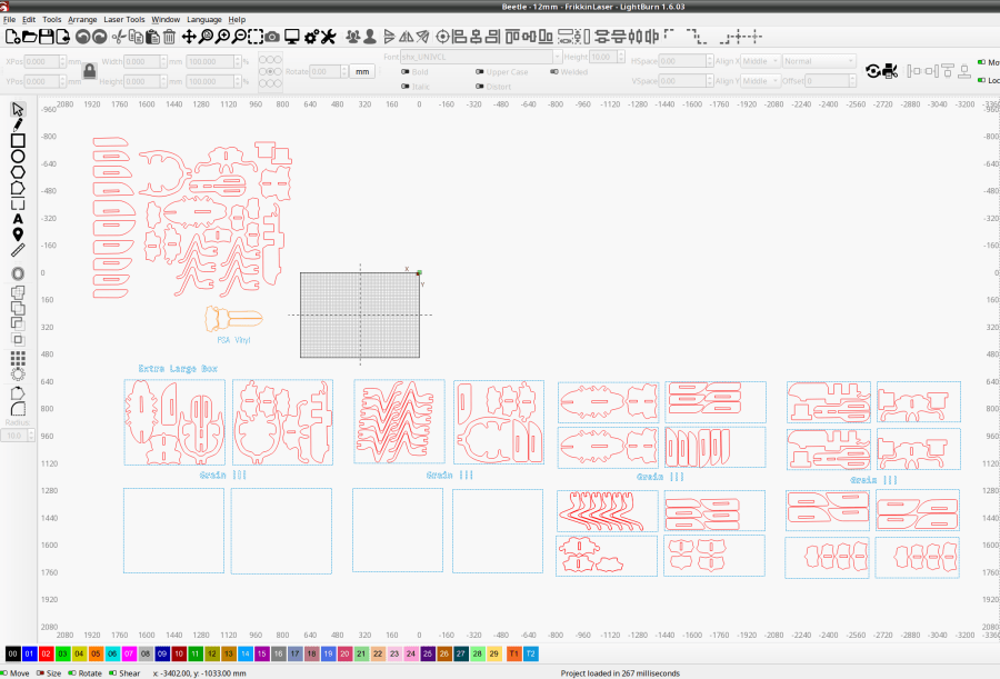
The gridded rectangle represents the 700×500 mm laser platform.
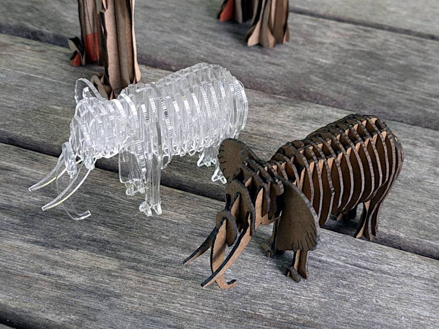
The little ones are kinda cute and not too threatening:

Yes, that is one of the Goldbug Variations.