Ed Nisley's Blog: Shop notes, electronics, firmware, machinery, 3D printing, laser cuttery, and curiosities. Contents: 100% human thinking, 0% AI slop.
The standard Sherline mill comes with tapered plastic knobs on the handwheels, which is exactly what you want for a manual mill and what you don’t want on a CNC machine: they rattle like crazy during computer-controlled moves.
Some folks contend the knob unbalances the handwheel, but I’m not convinced that’s a real problem. Their advice is to remove the entire knob assembly, leaving a bare shaft sticking out of the motor. Seems a bit extreme to me.
In any event, shortly after I got the mill, I unscrewed the little retaining screw from the end of each knob, put all the parts in a ziplock bag, tucked it in my tool box, and have been rattle-free ever since.
The metal shaft is entirely adequate for those rare occasions when I turn the knob manually, the graduated settings let me detect when if I’ve screwed up the acceleration (on a new installation) to the point where the motor is losing steps, and all is right with the world.
Oh, that orange-barred white tape in front of the motor? That’s a reminder to keep the usual pile of crap away from the spinning knob. That little shaft can fling small objects a fair distance and makes a nasty tangle out of a misplaced red rag…
The thumb roller fell off my digital caliper in the heat of a project, forcing me to deploy a hot backup from the upstairs desk.
This looks like a clear-cut case of underdesign, because it broke exactly where you’d expect: at the midpoint of the arch. Having my thumb right over the spot marked X, though, meant that I had all the pieces and could, at least in principle, glue everything back together.
Glued and clamped
As with all repairs involving adhesives, the real problem is clamping the parts together while the glue cures. I clamped a stack of random plastic sheets to the back of the case to establish a plane surface behind the mount, with a small steel shim to prevent the top sheet from becoming one with the repair.
The roller shaft was about the same size as a #33 drill and the opening was about 110 mils. Some 3/32″ (actually about 96 mils) rectangular telescoping brass tubing was about the right size & shape to hold the opening in alignment. Another length of tubing kept the broken part from sliding to the left.
A dab of solvent glue (I still use Plastruct, but it’s not like it used to be before it became less toxic) on both pieces, line ’em up, apply a clamp to hold it in place, and let it cure overnight.
I have no confidence that this will stay together for very long, so I’ll probably be forced to mill a little replacement mounting doodad.
Ought to be good for a few hours of quality shop time…
Memo to Self: Don’t run the slide off the end of the body, because that rubber boot is an absolute mumble to put back in place.
The Axis user interface for EMC2 has a manual command entry mode, wherein you can type G-Code statements and EMC2 will do exactly what you say. That’s handy for positioning to exact coordinates, but I rarely use it for actual machining, as it’s just too easy to mis-type a command and plow a trench through the clamps.
OK, on a Sherline mini-mill, you’d maybe just snap off a carbide end mill, but you get the general idea.
I was making a simple front panel from some ancient nubbly coated aluminum sheet. The LCD and power switch rectangles went swimmingly.
Then I tried to mill an oval for the test prod wires using G42.1 cutter diameter compensation. I did a trial run 1 mm above the surface, figured out how to make it do what I wanted, then punched the cutter through the sheet at the center of the oval and entered (what I thought were) the same commands by picking them from the history list.
EMC2 now handles concave corners by automagically inserting fillets, so it must run one command behind your typing. I drove the cutter to the upper-right end of the oval (no motion) so it could engage cutter comp mode, entered the G2 right endcap arc to the lower edge (cuts straight to upper right), and then did something wrong with the next command.
Epoxy-patched front panel hole
The cutter carved the endcap properly, then neatly pirouetted around the end and started chewing out an arc in the other direction. Even looking at the command trace I can’t figure out what I mistyped, but as it turns out it doesn’t matter… I was using the wrong dimensions for the hole anyway.
So it’s now patched with epoxy backed up by a small square of aluminum. When it’s done curing, I’ll manually drill a pair of holes at the right coordinates, manually file out the oval, shoot a couple of coats of paint, and it’ll be OK.
Nobody will ever know!
If I recall correctly, Joe Martin of Sherline was the first person to observe that, unlike word processing programs, CNC machines lack an Undo key…
Update: Like this…
Patched panel – rear view
The shoot-a-couple-of-coats thing did not go well: a maple seed landed on the front panel. Ah, well, it’s close enough. Here’s a trial fit; the bellyband height extenders on the sides need a dab of epoxy and a shot of paint, too, but I may never get a round ‘tuit for that.
Front panel trial fit
It’s the long-awaited Equivalent Series Resistance meter…
Having just finished tweaking the nosepieces on my new sunglasses into shape, it’s worth mentioning a few pliers you should have.
This set of pliers (PN HH02075SET) from Circuit Specialists is absolutely invaluable. Mine were about twice the current price; the picture looks the same.
You’ll use these four metal-forming pliers (PN 60398) from Micro-Mark somewhat less often, but when you need ’em (like for adjusting your glasses), you need ’em bad. Mine were about half the current price, but I’m sure they cost the same in constant dollars.
I picked up a bunch of surplus Plato 170 flush cutters a long time ago, but even their current price isn’t too forbidding. Great for circuit board work.
My simple collet pusher has been working OK, but the locking pin was a few mils too small for the hole in the spindle and eventually put a burr on the edge. The fix is straightforward, although I’ve been putting it off for far too long; I warned you about this in the original post.
The locking hole in the spindle starts life at 0.094 inch. I grabbed a #40 drill in a pin vise and drilled it out to 0.098 by hand, which wasn’t nearly as difficult as you’d think, took out all the deformed metal, and didn’t even leave any burrs. Ditto for the hole in the collet pusher.
My heap yielded a defunct #40 drill, from which I cut 15 mm of shank with a Dremel abrasive wheel. Chucked the shank stub in the drill press, spun it up, and applied a Dremel grindstone to put a very short taper and a nice smooth end on it.
Pulled the old pin from the handle I built a while ago, added a dot of urethane glue to the new pin, and squished them together (tapered end out!) in a vise until cured. Done!
If you’re building an Arduino shield, you must align the connectors & holes with the Arduino board underneath. That seems to be easy enough, assuming you start with the Eagle CAD layout found there, but when you’re starting with your own layout, then things get messy.
Here’s how to verify that you have everything in the right spot, at least for Diecimilla-class boards. Start by holding the Arduino board with the component side facing you, USB connector on the upper left. Rotate your own PCB layout appropriately or stand on your head / shoulders as needed.
With the exception of J3, the center points of the connectors & holes seem to be on a hard 25-mil grid with the origin at the lower-left corner of the board (below the coaxial power jack):
J3 (AREF) @ (1.290,2.000)
J1 (RX) @ (2.150,2.000)
POWER @ (1.550,0.100)
J2 (AIN) @ (2.250,0.100)
Upper-left hole = 0.125 dia @ (0.600,2.000)
Upper-right hole = 0.087 dia @ (2.600,1.400)
Lower-right hole = 0.125 dia @ (2.600,0.300)
Reset button = (2.175,1.065)
Offsets between points of interest:
connector rows Y = 1.900
right holes Y = 1.100
UL hole to UR hole = (2.000,-0.600)
UL hole to J3 X = 0.690
J3 to J1 X = 0.860
J3 to POWER X = 0.260
POWER to J2 X = 0.700
J1 to UR hole = (0.450,-0.600)
J2 to LR hole = (0.350,200)
Note that the three etched fiducial targets are not on the 25-mil grid. They’re not on a hard metric grid, either, so I don’t know quite what’s going on. Fortunately, they’re not holes, so it doesn’t matter.
Memo to self: perhaps I’ve measured & calculated & transcribed those values correctly. Double-check before drilling, perhaps by superimposing double-size PCB layouts on a light table or window. Finding it then is much less annoying than after drilling the board… ask me how I know.
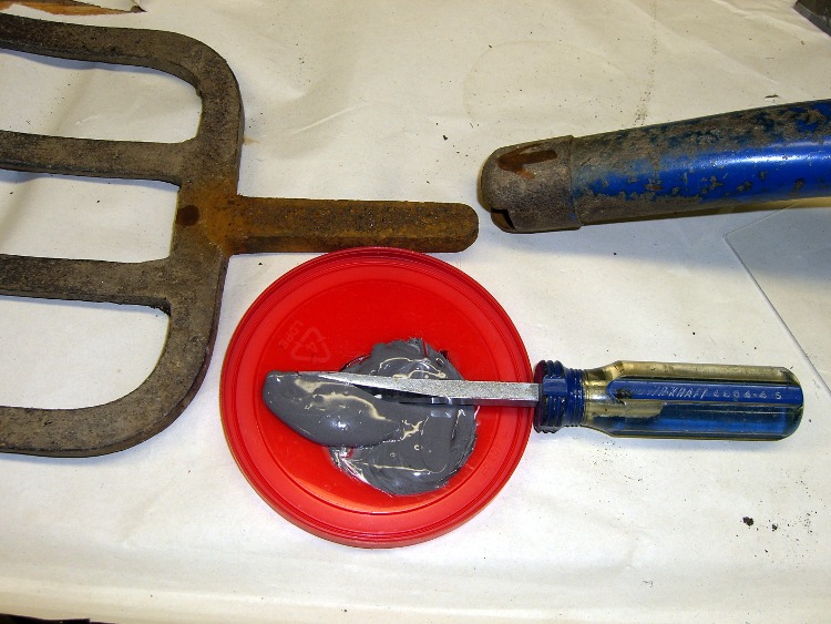
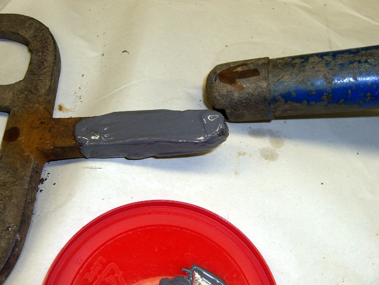
Mary intercepted a complete, albeit defunct, garden fork on its way to the trash and brought it home for repair. It turns out that the handle’s socket had loosened and split around the tine shank, but all the pieces were pretty much in place.
Mix the epoxy with my dedicated mixing screwdriver, butter up the shank, blob the excess epoxy into the socket, shove the parts together, clean off the outside globs, and let it cure overnight.
The trick is to get enough epoxy in the socket to fill the voids and mechanically lock the shank in place. This probably won’t work for forks used by burly guys who heave rocks over the horizon, but for our simple needs it’ll do just fine.
Pitchfork repair – epoxy mix
Pitchfork repair – buttering up the shank
Every now and again it’s OK to do an easy repair without a trace of CNC…