Ed Nisley's Blog: Shop notes, electronics, firmware, machinery, 3D printing, laser cuttery, and curiosities. Contents: 100% human thinking, 0% AI slop.
Being cyclists, we were doing the resuable-water-bottle thing long before it became trendy, but now that we use hydration packs, we just tote bottles along when we’re driving or on some other sort of outing. Eventually the bottles wear out / get lost and we page a new one in from the essentially infinite stash in the bottle cupboard.
This one had a cap that simply couldn’t be pried open with bare hands, no how, no way. I eventually got it open by main force and the threat of high temperatures.
Turns out there were two problems: the aperture in the pull-up ring is a wee bit small on the sealing nub and the ridge on the screw cap is about two wee bits large for the recess in the ring.
The former succumbed to an O (letter Oh) drill, which I pulled & pushed through the hole by hand to enlarge the aperture from 0.320 to 0.332. It still seals reasonably well, although it’ll pee a thin stream under more pressure than you should apply to such a bottle, which means I put a slight scratch on the aperture.
The latter required gently shaving the ridge with a box cutter (gasp). It’s still rather stiff, but entirely workable. That doesn’t affect the seal, because the ring’s skirt is a snug fit against the screw cap.
Why not just throw the fool thing out? After all, it’s just a freebie water bottle…
We run on the “Use it up, wear it out, fix it once, wear it out again, then put it on the shelf because maybe you can use the parts for something” principle.
Now, that’s not the way things are done these days, but it works for us…
The front ball joint on the mirror on Mary’s helmet loosened enough that the mirror blew out of position every time we got up to a decent traveling speed. I’ve repaired these mirrors several times before; they’re plastic and tend to fracture / wear out / break at inconvenient moments.
The first pic shows the mirror (the black surface is reflecting the dark floor joists overhead) with an old blob of epoxy that repaired a break in the outer socket. The socket originally had stylin’ curves joining it to the mirror, which proved to be weak spots that required epoxy fortification.
This time the socket split axially on the side away from the mirror, which released the pressure on the ball socket that seats into it. I found a chunk of brass tube that fit snugly over the socket, then carved some clearance for the existing epoxy blob. The key feature is that the tube remains a ring, rather than a C-shaped sheet. to maintain pressure around the socket.
Clamping the reinforcement ring
Here are the various bits, with the reinforcing ring clamped in place. I coated the socket exterior with JB Weld epoxy, slipped the ring in place, and tapped it down with a brass hammer to seat flush with the front face of the socket. That left gaps between the socket opening and the tube that I eased more epoxy into with an awl. A bit more epoxy around the exterior smoothed over that ragged edge.
The strut at the bottom of the picture ends in a ball joint held by a socket that slips into the mirror socket. The loose brass ring above the mirror is some shim stock that I added some years ago to take up slop between the ball socket and the mirror socket and tighten the ball joint. I suppose that pressure eventually split the outer socket, but so it goes.
Repaired mirror joint
The clamp squished the outer socket enough to snug it around the ball socket, so when I reassembled the mirror it was fine. To be sure, I dunked the ball in my lifetime supply of Brownell’s Powdered Rosin for a bit more non-slip stickiness.
I have a box full of defunct bike helmet mirrors, dating back to those old wire-frame square mirrors that clamped onto the original Bell helmets. The newer plastic ones just don’t last; we ride our bikes a lot and even fancy engineering plastic isn’t nearly durable enough. A few bits of metal here and there would dramatically improve the results!
I’m going to build some durable wire-frame mirrors, but … this will keep us on the road for a while. I suppose I should make a preemptive repair on my helmet mirror while I’m thinking of it…
Here’s a quick-and-easy way to improve the odds of your arriving home safely after dark: add snippets of retroreflective tape to the inside of the rims on your bike.
Do half the rim in one color and leave the other half untaped (or taped in a contrasting color) so that the rim flashes as the wheel rotates. I originally applied orange tape, of which I have very nearly a lifetime supply, then added white when I got a sheet as part of a surplus deal.
At 15 mph the 20-inch front wheel blinks at about 4 Hz, which is wonderfully attention-getting. The rear wheel, a more common 700C size, blinks at 3 Hz.
It helps to measure the space between spokes, then set up a template to cut all the tape pieces the same length. Wipe the big chunks of dirt off the rim, then remove the remaining grunge with alcohol so the tape actually sticks.
New York State vehicle law considers reflectorized tires as equal to those in-the-spokes reflectors, which is a Good Thing.
The more you look like a UFO after dark, the less surprised the drivers are and the less hassle you get.
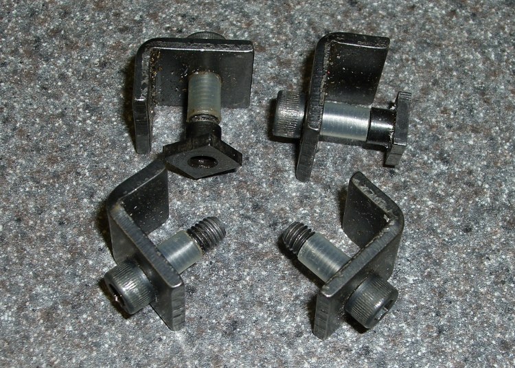
A small improvement: add a snippet of heat stink shrink tubing to the screw in the L-shaped hold-down clamps and the screw won’t go walkabout in your tooling widget case.
Make it the same length as the distance from the clamp to the surface and it’ll remind you how far to screw on the T-nut when you swap the clamps from tooling plate to milling machine table.
Sherline clamp screws with heatshrink
Sherline clamp in action
The Sherline Mill Vise (PN 3551) comes with a set of clamps. They’re also available separately as the 4-Jaw Hold-Down Set (PN 3058).
As I mentioned there, we have white LED bike headlights clamped to the amateur radio antennas on our bikes, facing rearward to eliminate the “But, Officer, I didn’t see him” line from the accident investigation. That works fine during daylight hours, but it’s rather blinding after dark and, in any event, taillights are supposed to be red (after 1 Nov 2009, they may also be amber).
The easiest way to get that result, without having to tote along Yet Another Light, is to slip a red filter over the white LED lens. This dramatically reduces the light output, because the yellow phosphor used to get white light out of what’s basically a blue LED doesn’t emit much energy in the red end of the spectrum, but it’s plenty good enough to be seen from the requisite 300 feet.
Amber filters would be a much, much better match to the phosphor and I’ll use them next year when they’re legal.
For what it’s worth, we’ve discovered that the more we look like UFOs after dark, the more clearance we get. The bikes are extensively reflectorized and lighted, plus we have reflective arm and leg bands. If somebody hits us, it’s because they did it intentionally; that’s usually the story with drunks and punks, alas.
Red filter components
I cut two transparent disks from ordinary electronics packaging material, plus a red disk from the Primary Red filter material mentioned there, stacked them on the headlight, and fired some big heat stink shrink tubing around them. The tubing extended maybe 3 mm past the end of the headlight and shrank into a neat lip that matched the bezel around the lens.
The tool to have for this sort of job is an Olfa Compass Circle Cutter. It leaves a pin prick in the center of the circle, but if you’re gentle that won’t be a problem in this application.
The shrunken tubing will be exceedingly difficult to pull off the headlight, so you may want to wrap a layer of tape around the bezel before shrinking. Peel the tape off when you’re done and the tubing will have a few mils more clearance.
No adhesive on earth will stick to both the polypropylene disks and the heatshrink tubing, but you can try silicone snot if you want. I made the disks just slightly larger than the bezel so that the tubing captures them as it shrinks. These things spend much of their lives in a ziplock baggie, so durability isn’t an issue.
Red filter installed
In any event, the filter looks like this when it’s installed. Because of the odd way I mounted the headlights, the side lenses aren’t visible (and they’re white, not red), but we have plenty of other light visible from the side.
For the straight dope on current NYS bicycle laws, go there, click on the “Laws of New York” link, search for “bicycle”, then click on section 1236. It’s New York’s idea of a useful Web interface: get over it.
The bezels on our lights are beginning to crack, so it’s probably time to start thinking about a killer street-legal day/night amber taillight. High intensity LEDs are dirt cheap these days…
Usually I replace the blade on my ancient (cast iron!) 14-inch Delta band saw when I can no longer force it through the thing-to-be-cut, which means every few years, tops, unless I procrastinate. Having just stripped the teeth off a foot of blade, it was time for a replacement long before one was due…
The first step is whacking off 93″ of blade from the 100-foot coil I bought ever so many years ago, using a cold chisel on the vise’s anvil surface. If you’re fussy, wrap a piece of duct tape around the ends-to-be so they don’t fly away after the cut. Otherwise, just enjoy the twang and risk some ritual scarification.
Scarfing the blade ends
Clamp the blade to the top of the vise with a half-twist so opposite sides face up, then scarf both ends about halfway through, so the finished joint will be more-or-less the same thickness as the rest of the blade. Chuck up a grinding wheel / cylinder in your Dremel-tool-like gadget, go slow so as to not overheat the joint, and shower your workbench with steel dust.
To emphasize: note that the teeth face this way on one end and that way on the other! You might want to butt the ends together, but I’m not sure I could get the taper thin enough in the middle that way. You want to cut about halfway through the width of the teeth, too, because they must overlap in the finished joint.
Preparing solder foil
I use a homebrew resistance soldering gadget, but a honkin’ big soldering gun might work. In any event, solder foil works better than solder wire, so I put a snippet of Brownell’s Hi-Force 44 4% silver solder (far more expensive now than when I bought that 1-lb spool long ago) in a stainless-steel sleeve and massage it with a hammer. Crude, but effective: the point is to keep the solder clean, which doesn’t happen when you just whack it on the anvil.
Aligning and clamping blade ends
However you do the joint, you must align the blade ends so they’re collinear: you do not want a kink in the middle of the blade. This setup reflects my soldering gear: a graphite slab clamped to a brass plate caught in the vise, an aluminum channel for alignment, and a pair of battery clamps to hold the blade in place. I apply paste flux to both sides of the joint and poke the solder foil into the flux, too. If you squint, you can see the trimmed-to-fit solder foil lying atop the scarfed edge.
Resistance soldering
Slide the right side over the left, make sure the teeth on both ends overlay each other, clamp in place, check the alignment, and apply heat. This is a slightly staged shot showing the carbon gouging rod in position well after the joint has solidified. The key advantage of resistance soldering is having a footswitch so you can hold everything in position while the joint cools.
Thinning the joint
Clamp the finished blade to the vise and thin both sides to the width of the rest of the blade. If you’ve done a better job of scarfing than I usually do, this is just a matter of tapering the edge a bit. The pic shows the first surface I thinned, so there’s some flux hanging in the teeth. That’ll vanish as you cut if you don’t clear it off while thinning.
Finished joint – victim's view
The end result should look like this, as seen from the victim’s position in the bandsaw: no lumps, no bumps, nothing sticking out on either side.
The whole process takes about half an hour, what with clearing space on the workbench, setting up the soldering gear, deploying the Dremel tool, and cleaning up a bit afterward. That would be crazy in a production environment, which is why they have blade welders bolted to the side of the bandsaws, but it’s OK for something I do every few years.
I formerly used a propane torch and a fixture to align the pieces, but the resistance soldering unit eliminates the flame and delivers a much better result because it compresses the joint while the solder cools.
Side views, just for completeness…
Finished joint – left sideFinished joint – right side
The gear cover is an elaborate ten-pound iron casting, emblazoned with brass tags, and held in place by three 1/4-20 machine screws. The back gear covers, visible in the upper-left corner, are the same sort of wonderfully complex iron casting.
Make magazine, issue 17, has a snippet about an old sorghum press with instructions cast right into the machine, so you could literally RTFM: Read The Ferrous Metal. As it turns out, this 1928 South Bend lathe has instructions stamped into machined metal areas atop the change gear train: OIL.
Here’s a closeup…
Read The Ferrous Metal
Think about it: an iron casting, with machined-flat surfaces, stamped with instructions. How many man-hours did it take to get from raw material to finished product?