The Smell of Molten Projects in the Morning

Ed Nisley's Blog: Shop notes, electronics, firmware, machinery, 3D printing, laser cuttery, and curiosities. Contents: 100% human thinking, 0% AI slop.

Category: Machine Shop

Mechanical widgetry

  • Platform Level Test Pattern

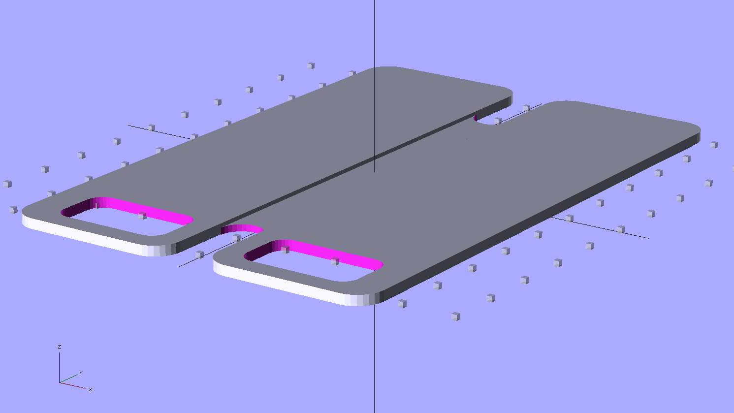
    Unlike that pattern, this OpenSCAD program produces an STL file that gets sliced in the usual manner, so that the end result shows exactly how the first layer of all other objects gets laid down.

    Thread Thickness Test - solid model
    Thread Thickness Test – solid model

    It’s two threads wide and one thread thick: customize the OpenSCAD code to match the settings in Skeinforge (or Slic3r or whatever you’re using) to make it build properly.

    The two tabs mark the +X and +Y directions. The bottom surface will be wonderfully shiny from the build plate, so the symmetry along the diagonal shouldn’t pose a problem.

    Should the thickness vary more-or-less linearly along any of the bars, then you know which way to level the platform. If it varies non-uniformly, then either the build plate isn’t flat or the printer has other problems.

    The actual width depends on the actual thickness, of course: a too-low nozzle will create a too-wide pattern regardless of the extrusion settings. The thickness should be uniform across the entire pattern, so you can still adjust the platform leveling screws.

    If you’re using a Z-minimum platform height sensor, now’s the time to adjust the switch touch-off height to make the thread thickness come out right.

    When the thread thickness comes out right, then the width should match the extrusion settings: the bottom layer will be exactly like all the others. That’s the ideal situation, anyway.

    A thickness snap gauge comes in handy for this sort of thing.

    The OpenSCAD source code:

    // Platform Level test pattern
    // Ed Nisley KE4ZNU - Dec 2011
    
    //-------
    //- Extrusion parameters must match reality!
    
    ThreadThick = 0.25;
    ThreadWidth = 2.0 * ThreadThick;
    
    //-------
    // Dimensions
    
    BoxSize = 80;
    
    //-------
    
    module ShowPegGrid(Space = 10.0,Size = 1.0) {
    
      Range = floor(50 / Space);
      for (x=[-Range:Range])
        for (y=[-Range:Range])
          translate([x*Space,y*Space,Size/2])
            %cube(Size,center=true);
    }
    
    //-------
    
    ShowPegGrid();
    
    for (Index=[0:3])
      rotate(Index*90)
        translate([0,BoxSize/2,ThreadThick/2])
          cube([BoxSize,2*ThreadWidth,ThreadThick],center=true);
    
    for (Index=[-1,1])
      rotate(Index*45)
        translate([0,0,ThreadThick/2])
          cube([sqrt(2)*BoxSize,2*ThreadWidth,ThreadThick],center=true);
    
    translate([BoxSize/2,0,ThreadThick/2])
      cube([BoxSize/6,2*ThreadWidth,ThreadThick],center=true);
    
    translate([0,BoxSize/2,ThreadThick/2])
      rotate(90)
        cube([BoxSize/6,2*ThreadWidth,ThreadThick],center=true);
    
  • Kitchen Countertop Splice

    When we rearranged the kitchen after installing the laminate flooring, I conjured up a countertop to replace the ancient one over a cabinet left standing in one end of the kitchen where the new refrigerator didn’t fit. This was a temporary measure until we built an additional cabinet adjacent to the old one and laid a single countertop over the whole affair. Having several short lengths of generic gray countertop left over from the Black Bathroom, laundry, and the other side of the kitchen, I butt-glued two hunks together with a small block of wood underneath as a support.

    Time passes, we never did get around to building the other cabinet, and eventually the weight of the microwave and mixer bowed the poorly supported joint until it broke free and deposited the mixer on the floor.

    Both pieces being bowed, I screwed some angle bracket underneath to straighten them out, clamped them together, laid a piece of tape over the joint, and match-marked the dowel locations:

    Countertop - match-marked joint
    Countertop – match-marked joint

    Drilled holes for 1/4 dowel pins that I sliced off a length of aluminum rod (no sissy wood pins for me!):

    Countertop - dowel hole jig
    Countertop – dowel hole jig

    Slobbered epoxy over the pins with enough into the holes for good adhesion, then buttered up the joint to fill the voids:

    Countertop - underside braces and joint
    Countertop – underside braces and joint

    Put more tape over the countertop, sliced out the gap, and buttered up the top surface to fill the joint:

    Countertop - filling joint
    Countertop – filling joint

    That works because JB Industro-Weld Epoxy turns out to be a nearly perfect color match:

    Countertop - final joint
    Countertop – final joint

    Those angle brackets remain in place underneath the surface in the hope they’ll prevent it from bowing again. An aluminum strip (not yet installed in these pix) fills the recess below the backsplash to level it with the underside of the countertop, providing more support over the back of the cabinet case.

    The whole affair took a few days, what with curing successive epoxy applications overnight. Got to use some tools that don’t often see the light of day, too, which is always good fun.

    Maybe we’ll build that other cabinet some day…

  • Thing-O-Matic: Improved EC Thermistor Connector Orientation

    Given that the SMD pads fell off the HBP circuit board and I must replace the connector, I figured I may as well also replace the remarkably stiff MBI thermistor cable with a much more flexible CD-ROM audio cable. Although the EC end of the MBI cable looks like a standard CD-ROM audio connector, it’s been rewired. No problem: this is not an audio application and I’m going to do exactly the same thing.

    The Extruder Controller, however, doesn’t have a matching connector and the recommended attachment involves simply jamming the connector onto the pin header, per this detail cropped from that photo in the MBI assembly instructions:

    MBI EC HBP Thermistor Connector Alignment - Detail
    MBI EC HBP Thermistor Connector Alignment – Detail

    Here’s a better closeup of my EC, taken from the other side:

    MBI Extruder Controller - HBP thermistor connector
    MBI Extruder Controller – HBP thermistor connector

    The header block breaks out the Arduino’s Analog Input pins, with A6 in the front of that photo. From left to right, the pins under the HBP connector are A6 / +5 V / Gnd. Unfortunately, the connector wiring and alignment puts the thermistor signal on the cable shield, with the Gnd and +5 V wires safely tucked inside. This is, shall we say, suboptimal.

    The Gnd connection provides a low-impedance connection to the least-noisy part of the circuit, so putting it on the shield tends to prevent the relatively high-impedance signals within from picking up noise. This isn’t always successful, for a number of reasons, but it’s a Good Idea.

    Although probably doesn’t make much difference (it’d just add a bit of noise to the HBP temperature signal), but if I’m going to be rewiring it anyway, the cable shield will be at ground potential with the signal  wire inside. Here’s my cable & connector, rearranged to make that so:

    EC HBP thermistor connector - revised
    EC HBP thermistor connector – revised

    The analog audio connector on the back of old-school CD-ROM drives, back before digital audio output from the drives actually worked, had four pins:

    • Left (white) and Right (red) audio channels on the outer pair
    • Ground (black) on at least one of the central pair

    So the red wire will be in the far right-hand socket of the connector shell; depress its locking tab, slide it out of the shell, poke it into the socket between the other two wires, push to click, and you’re set. Conveniently, this puts the +5 V supply on the red wire, which is sorta-kinda standard. Your cable colors may vary; pay attention to the actual wiring and ignore the color code!

    Tape the connector in place (with the empty socket now toward the board edge) to prevent the tangle of wires in the Thing-O-Matic’s electronics bay from dislodging it at an inopportune moment:

    EC HBP thermistor connector - secured
    EC HBP thermistor connector – secured

    Admittedly, that arrangement still tucks the +5V wire right next to the signal wire inside the shield, but it’s a step in the right direction.

    You could flip the MBI cable around, too, as long as you also rearranged the pins at the HBP end to match.

  • Thing-O-Matic: HBP Connector Failure

    This has been a long time coming, as the connector shell over that pin connecting the MOSFET to the heater has been getting crispier despite my attention, cleaning, and occasional DeoxIT application.

    Burned-out HBP connector
    Burned-out HBP connector

    Notice that the burned pin now stands at a slight angle to the others. The PCB pad has no additional copper traces on that side to conduct the heat away from the failing connection, so the joint got hot enough to put the solder into its semi-liquid state, whereupon the springy connector rammed it upwards through the softened plastic shell. If the PCB fab shop used 60-40 lead solder, that’s around 188 °C. Silver solder would reach 220-ish °C. If the solder was eutectic, it would turn liquid and just drip off.

    What doesn’t show: the SMD pads that pulled free from the PCB surface, fortunately only under the rightmost three pins leading to the thermistor. Repairing the pads and connector makes no sense, so I think I’ll go with pigtail leads anchored to the plywood, with offboard connectors to reduce the strain on those pads. Powerpoles will be bulky, but maybe pigtails long enough to get them onto the case might work.

    As a general rule, soldering wires or connectors to SMD pads with no mechanical support is a Bad Idea and applying repeated mechanical stress to those connectors is a Very Bad Idea. Doing all that on a PCB running well over 100 °C with current right up near the connector’s absolute maximum, well…

  • Extruder Speed Control Puzzle

    The Retraction speed in the Skeinforge Dimension plugin sets the E axis speed while it’s inhaling molten filament at the end of each thread and exhaling it at the start of the next thread. For a Retraction speed of 60 mm/s = 3600 mm/min and a Retraction Distance of 2 mm, the G-Code at the very start of the Skirt thread looks like this:

    G1 F3600.0
    G1 E2.0
    

    So far, so good; that, I can understand. The extruder spins at a pretty good clip, but only while moving 2 mm of filament.

    The Dimension plugin doc explains the settings for its parameters, but isn’t forthcoming on the subject of what to use for the Flow rate in the Speed plugin. The Speed plugin doc doesn’t help much; it seems the Flow rate uses either PWM or mm/s, depending on something imponderable. Per that discussion, you should apparently set both Feed and Flow to the same value (in mm/s), which I have done. Given that G-Code has only one speed setting for coordinated motion, that seems reasonable.

    For a Feed speed of 60 mm/s = 3600 mm/s (which may seem aggressive, but that’s what acceleration limiting enables), the G-Code at the start of the second layer looks like this:

    G1 X-3.5302 Y-26.3671 Z0.5 F3600.0 E141.3026
    G1 X2.7622 Y-22.7342 Z0.5 F3600.0 E141.4484
    G1 X9.0546 Y-26.3671 Z0.5 F3600.0 E141.5941
    

    However, that seems to mean the extruder rams filament into the hot end at 3600 mm/min = 60 mm/s, which simply isn’t what’s going on. The pinch wheel / gear / whatever turns at maybe 2 rev/min, which corresponds to about 60 mm/min: roughly 1/60 the speed indicated by the F3600.0 parameter.

    The SJFW M201 parameter was set to E60, which should set 60 mm/min as the minimum speed. But Skeinforge doesn’t know anything about the firmware’s internal minimum (or maximum!) speed limits.

    So I tried a few manual variations with the extruder heated up, feeding in commands like G1 E10 Fnn, with various nn values for the F speed, while measuring the elapsed time. If F sets the extruder speed in mm/min, then the time to extrude 10 mm of filament should vary inversely with the speed. Some results:

    • F240 → 10 s
    • F360 → 10 s
    • F400 → 11 s
    • F450 → 1 s
    • F480 → 1 s

    Huh. Now that, I do not understand.

    Setting M201 E120, which should double the minimum speed, produces these reasonable results:

    • F1 → 10 s
    • F2 → 7 s
    • F3 → 6 s
    • F4 → 3 s
    • F5 → stalls because the extruder can’t maintain that pace

    The first line seems to indicate that extruding 10 mm of filament at 1 mm/min requires 10 seconds, which is off by a neat factor of 1/60. The ratio of the lines is more-or-less right, as long as you allow more measurement windage than seems appropriate and ignore the gross overall speed mismatch. The difference between the two sequences is not the ratio of the two M201 settings, however.

    I have the extruder set to accelerate at 250 mm/s2, which implies it can reach 120 mm/min = 2 mm/s in 0.008 mm, which is basically instantly. Relevant equation: x = v2/2a.

    Given the incoming filament diameter and the outgoing extrusion thread dimensions, Skeinforge knows their cross-sectional areas.  Multiplying the extrusion thread’s cross-section area by the Pythagorean XY distance for a segment gives the extrusion volume, dividing that by the filament cross-section area gives the incoming filament length, and dividing that by the Filament Packing Density fudges the answer to come out right.

    From the coordinates in the first two lines of G-Code we have:

    • XY distance = 7.27 mm
    • extrusion distance = 0.15 mm

    Given the corresponding extrusion settings:

    • 0.25 mm layer height and 0.50 mm width = 0.125 mm2
    • 2.89 mm filament dia = 6.56 mm2
    • FPD=0.95

    The incoming distance works out to (0.125 * 7.27 / 6.56) / 0.95 = 0.15 mm, which is dead on the G-Code value. So I understand the volume part, at least.

    At the Feed rate of 60 mm/s, the extruder covers the XY distance in 7.27 / 60 = 0.12 s. The extruder must consume 0.15 mm of filament in that same time, which works out to 0.15 / 0.12 = 1.2 mm/s = 72 mm/min.

    Obviously, the extruder filament drive is not running at the F3600.0 value set by the G-Code, nor is it running at 1/60 that speed.

    I have not the foggiest idea what’s going on in there, but … it seems to work. Equally obviously, because Skeinforge doesn’t know which firmware I’m using, all the firmware usable with Dimension behaves the same way.

    One possibility: perhaps the E axis (definitely not XY and probably not Z) runs in something resembling EMC2’s inverse time mode, wherein the firmware adjusts the speed to complete the move in a fixed time. In this case, the firmware knows both the distance (given by Skeinforge in the E parameter) and the time for the XY move (found by dividing that XY Pythagorean distance by the F parameter), so it can compute the speed required to make the extruder poot out the right amount of plastic in that time, presumably while imposing (trapezoidal?) acceleration limiting along the way.

    That might also account for the weird behavior with M201 E60 shown above: perhaps the firmware uses a stale time left over from the most recent XY motion to compute the speed for a move involving only the E axis. I suppose I could puzzle through the source; it’s rather daunting.

    Anybody have any clues or pointers to the obvious doc I’ve overlooked?

  • Cleaning 3D Printed Recesses

    Having used screwdrivers and other improvised tools to clean out various 3D printed recesses, it finally penetrated my thick consciousness that a boring bar is exactly the right hammer for the job:

    Cleaning screw head recesses with a boring bar
    Cleaning screw head recesses with a boring bar

    In normal use, a boring bar’s head cuts mainly on its end surface, with the side cleaning up the hole’s periphery. Those edges remove droopy threads and Reversal zittage around a hole’s interior; an end mill works better to make the recess uniformly deeper.

    I have a few sets of these things, with larger & smaller cutting ends and longer & shorter shanks, that I occasionally use for lathe boring and rarely for mill boring (in the manual mill, not the Sherline!). The smallest head in the collection is maybe 4 mm across, so there’s a definite lower limit on the size of the hole they’ll clear.

    Hand-held while cutting plastic? They’ll last forever!

    I should probably print up some handles…

  • Planet Bike Superflash: Tour Easy Mount

    Having not yet gotten around to building better taillights for our bikes, we picked up some Planet Bike Superflash lights on sale. I don’t like single-LED lights, because the optics produce a concentrated beam (which is how they get such high lumen ratings) that’s essentially invisible anywhere off-axis; a taillight that requires careful alignment for maximum effect is a Bad Thing. But, eh, they were on sale…

    The graceful OEM seatpost mount, done in engineering plastic with smooth curves and something of a reputation for fragility, doesn’t work on a recumbent, so I build a butt-ugly mount that should last forever. It clamps firmly around a length of grippy silicone tape on the top seat frame rail:

    Superflash on Tour Easy
    Superflash on Tour Easy

    The reviews also complain that normal road vibrations transmitted through the somewhat whippy OEM mount pop the case apart, depositing the lens and electronics on the road behind you. Hence the black tape across the case joint.

    Here’s the whole affair on the bench:

    Superflash on mount
    Superflash on mount

    The weird color line comes from white plastic left in the extruder that covers the bottom layer or two of each part. I’m not fussy about the first pass of any new gadget, because I know I’ll build at least one more to get everything right.

    This is the first build arrangement; note the huge white teardrop blob at the start of the Skirt outline on the left. Obviously I didn’t have the initial retraction under control:

    Superflash mount on build platform
    Superflash mount on build platform

    The screw recesses built over the plate and got cute little support spiders to keep their interiors from sagging:

    Superflash mount - bolt support
    Superflash mount – bolt support

    After doing it that way, I flipped the top piece over so it builds with the screw head recesses upward to get a better finish on those nice curves. That means the arch needs support, which almost worked, although some of the fins fell over:

    Superflash mount - failed arch support
    Superflash mount – failed arch support

    The solid model now adds a two-layer-thick flat plate joining the fins that should hold them firmly to the build plate.

    Clamp Support - Solid Model
    Clamp Support – Solid Model

    I also added an option to build the flash mounting shoe separately:

    Superflash mount - solid model
    Superflash mount – solid model

    That gives better control over the flange thickness, which turns out to be critical parameter requiring a bit of adjustment with a file in the first version. Of course, the shoe needs an alignment pin and another assembly step to glue it in place:

    Superflash mount - gluing shoe
    Superflash mount – gluing shoe

    A 4-40 setscrew jams into the latch recess in the Superflash case, thus preventing it from walking off the shoe. You don’t need any particular pressure here, just enough protrusion to engage the case:

    Superflash mount - setscrew
    Superflash mount – setscrew

    The first pass at hex nut recesses were exactly cos(30) too large, as I forgot my Useful Sizes file has the across-the-points diameter, so I added a dab of epoxy to each recess before gluing the halves together with solvent:

    Superflash mount - glue clamping
    Superflash mount – glue clamping

    And then it’s all good.

    The OpenSCAD source code:

    // Planet Bike Superflash mount for Tour Easy seatback
    // Ed Nisley KE4ZNU - Dec 2011
    
    Layout = "Show";            // Assembly: Show
                                // Parts: Clamp Base Shoe Mount
                                // Build Plate: Build
    
    SeparateShoe = true;        // true = print mounting shoe separately
                                // false = join shoe to Mount block
    
    Support = true;             // true = include support
    
    Gap = 8;                    // between "Show" objects
    
    include </home/ed/Thing-O-Matic/lib/MCAD/units.scad>
    include </home/ed/Thing-O-Matic/Useful Sizes.scad>
    include </home/ed/Thing-O-Matic/lib/visibone_colors.scad>
    
    //-------
    //- Extrusion parameters must match reality!
    //  Print with +1 shells, 3 solid layers, 0.2 infill
    
    ThreadThick = 0.25;
    ThreadWidth = 2.0 * ThreadThick;
    
    HoleFinagle = 0.1;
    HoleFudge = 1.00;
    
    function HoleAdjust(Diameter) = HoleFudge*Diameter + HoleFinagle;
    
    Protrusion = 0.1;           // make holes end cleanly
    
    function IntegerMultiple(Size,Unit) = Unit * ceil(Size / Unit);
    function IntegerMultipleMin(Size,Unit) = Unit * floor(Size / Unit);
    
    //-------
    // Dimensions
    
    BarDia = (5/8) * inch;              // seat back rail diameter
    BarRad = BarDia/2;
    
    TapeThick = 0.3;                    // grippy tape around bar
    
    HoleDia = BarDia + 2*TapeThick;     // total hole dia
    HoleRad = HoleDia/2;
    HoleSides = 4*5;
    
    echo("Bar hole dia: ",HoleDia);
    
    TightSpace = 1.0;                   // space for tightening screws
    
    PlateWidth = 20.0;                  // mounting plate across flanges
    PlateLength = 20.0;                 //  ... parallel to flanges
    PlateThick = IntegerMultipleMin(1.96,ThreadThick);          //  ... thickness
    FlangeThick = IntegerMultiple(1.40,ThreadThick);            // lamp flange thickness
    FlangeWidth = 2.0;                  //  ... width
    
    ShoeThick = PlateThick + FlangeThick;    // dingus protruding from main block
    ShoeOffset = 1.0;                   // offset due to end wall
    
    echo("Shoe thickness: ",ShoeThick," = ",PlateThick," + ",FlangeThick);
    
    LockOffset = -5.0;                  // offset of locking setscrew
    
    TopRoundRad = 1.5*Head10_32/2;      // tidy rounding on top edge of clamp
    echo("Top rounding radius: ",TopRoundRad);
    
    NutDia = Nut10_32Dia*cos(30);       // adjust from across-points to across-flats dia
    NutPart = IntegerMultiple(0.5*Nut10_32Thick,ThreadThick);  // part of nut in each half
    
    BoltOffset = HoleRad + max(Head10_32,NutDia);
    BoltClear = Clear10_32;
    BoltHeadDia = Head10_32;
    BoltHeadThick = Head10_32Thick;
    
    MountWidth = PlateLength + ShoeOffset;         // side-to-side
    MountLength = HoleDia + 3.5*max(BoltHeadDia,NutDia);
    
    ClampHeight = TopRoundRad + HoleRad;            // includes gap/2 for simplicity
    BaseHeight = NutPart + HoleRad;                 //  ... likewise
    MountHeight = PlateWidth;
    
    echo("Mount width: ",MountWidth," length: ",MountLength);
    echo("Height of clamp: ",ClampHeight," base: ",BaseHeight," mount: ",MountHeight);
    echo(" total: ",ClampHeight+BaseHeight+MountHeight);
    
    AlignPegDia = 2.9;                  // shoe alignment peg
    AlignPegLength = ShoeThick;
    
    echo("Alignment peg length: ",AlignPegLength);
    
    //-------
    
    module PolyCyl(Dia,Height,ForceSides=0) {           // based on nophead's polyholes
    
      Sides = (ForceSides != 0) ? ForceSides : (ceil(Dia) + 2);
    
      FixDia = Dia / cos(180/Sides);
    
      cylinder(r=HoleAdjust(FixDia)/2,h=Height,$fn=Sides);
    }
    
    module ShowPegGrid(Space = 10.0,Size = 1.0) {
    
      Range = floor(50 / Space);
    
        for (x=[-Range:Range])
          for (y=[-Range:Range])
            translate([x*Space,y*Space,Size/2])
              %cube(Size,center=true);
    }
    
    //-------
    // Upper clamp half
    
    module Clamp() {
    
      difference() {
        translate([0,0,-TightSpace/2]) {
          difference() {
            translate([0,0,ClampHeight/2]) {
              intersection() {
                translate([0,0,-TopRoundRad])
                  minkowski() {
                    cube([(MountLength - 2*TopRoundRad),
                          (MountWidth - 2*Protrusion),
                          ClampHeight],center=true);
                    rotate([90,0,0])
                      cylinder(r=TopRoundRad,h=Protrusion,$fn=4*8);
    
                  }
                cube([MountLength,MountWidth,ClampHeight],center=true);
              }
            }
            translate([0,(MountWidth/2 + Protrusion)])
              rotate([90,0,0])
                PolyCyl(HoleDia,(MountWidth + 2*Protrusion),HoleSides);
            for (Index=[-1,1])
              translate([(Index*BoltOffset),0,0]) {
                translate([0,0,-Protrusion])
                  PolyCyl(BoltClear,(ClampHeight + Protrusion));
                translate([0,0,(ClampHeight - BoltHeadThick)])
                  PolyCyl(BoltHeadDia,(BoltHeadThick + Protrusion));
              }
          }
    
        }
        translate([0,0,-TightSpace/2])
          cube([(MountLength + 2*Protrusion),
               (MountWidth + 2*Protrusion),
               TightSpace],center=true);
      }
    
        if (Support)                    // choose support to suit printing orientation
          union() {
            translate([0,0,1.5*ThreadThick])
              cube([0.75*HoleDia,(MountWidth + 2*ThreadWidth),3*ThreadThick],center=true);
            intersection() {
              for (Index=[-3:3])
                translate([0,Index*(MountWidth/6),-TightSpace/2])
                  rotate([90,0,0])
                    cylinder(r=(HoleRad - 0.25*ThreadThick),
                            h=2*ThreadWidth,center=true,$fn=HoleSides);
              translate([-HoleRad,-MountWidth,0])
                cube([HoleDia,2*MountWidth,HoleRad]);
            }
          }
    }
    
    //-------
    // Lower clamp half = base
    
    module Base() {
    
      difference() {
        translate([0,0,-TightSpace/2])
          difference() {
            translate([0,0,BaseHeight/2])
              cube([MountLength,MountWidth,BaseHeight],center=true);
            translate([0,(MountWidth/2 + Protrusion)])
              rotate([90,0,0])
                PolyCyl(HoleDia,(MountWidth + 2*Protrusion),HoleSides);
            for (Index=[-1,1])
              translate([(Index*BoltOffset),0,0]) {
                translate([0,0,-Protrusion])
                  PolyCyl(BoltClear,(BaseHeight + Protrusion));
                translate([0,0,(BaseHeight - NutPart)])
                  rotate(30)
                    PolyCyl(NutDia,(NutPart + Protrusion),6);
    //              cylinder(r=NutDia/2,h=(NutPart + Protrusion),$fn=6);
              }
          }
        translate([0,0,-TightSpace/2])
          cube([(MountLength + 2*Protrusion),
               (MountWidth + 2*Protrusion),
               TightSpace],center=true);
    
      }
    
      if (Support)
        for (Index=[-1,1])                  // support inside nut openings
          translate([(Index*BoltOffset),
                    0,
                    (BaseHeight - (NutPart - ThreadThick) - TightSpace/2)]) {
            translate([0,0,0])
              for (Seg=[0:5]) {
                rotate(30 + 360*Seg/6)
                  cube([NutDia/2,2*ThreadWidth,NutPart - ThreadThick],center=false);
              }
          }
    
    }
    
    //-------
    // Superflash mounting shoe
    // Offset by -ShoeOffset/2 in Y to align on Mount (half of total offset on each side)
    
    module Shoe() {
    
        difference() {
          translate([-ShoeThick/2,-ShoeOffset/2,PlateWidth/2])
            if (SeparateShoe)
              cube([ShoeThick,PlateLength,PlateWidth],center=true);
            else
              cube([(ShoeThick + Protrusion),PlateLength,PlateWidth],center=true);
    
          translate([-(FlangeThick - Protrusion),
                    -(PlateLength/2 + ShoeOffset/2 + Protrusion),
                    (MountHeight - FlangeWidth)])
            cube([FlangeThick,(PlateLength + 2*Protrusion),(FlangeWidth + Protrusion)]);
    
          translate([-(FlangeThick - Protrusion),
                    -(PlateLength/2 + ShoeOffset/2 + Protrusion),
                    -Protrusion])
            cube([FlangeThick,(PlateLength + 2*Protrusion),(FlangeWidth + Protrusion)]);
    
          translate([-(ShoeThick + Protrusion),LockOffset,MountHeight/2])
            rotate([0,90,0])
              rotate(0)                 // align to match Mount hole orientation
                PolyCyl(Tap4_40,(ShoeThick + 2*Protrusion));
    
          if (SeparateShoe)
            translate([-(ShoeThick - AlignPegLength/2),0,MountHeight/2])
              rotate([0,90,0])
                PolyCyl(AlignPegDia,AlignPegLength);
        }
    }
    
    //-------
    // Bottom block for Superflash mount
    
    module Mount() {
    
      translate([0,0,MountHeight/2])
        union() {
          difference() {
            union() {
              translate([-MountLength/4,0,0])
                cube([MountLength/2,MountWidth,MountHeight],center=true);
              translate([((MountLength/2 - MountHeight)/2 + Protrusion),0,0])
                cube([(MountLength/2 - MountHeight + 2*Protrusion),
                     MountWidth,
                     MountHeight],center=true);
              translate([(MountLength/2 - MountHeight),0,0])
                intersection() {
                  translate([MountLength/4,0,0])
                    cube([MountLength/2,MountWidth,MountHeight],center=true);
                  translate([0,0,MountHeight/2])
                    rotate([90,0,0])
                      cylinder(r=MountHeight,h=MountWidth,center=true,$fn=4*16);
                }
            }
    
            translate([-(MountLength/2 + Protrusion),LockOffset,0])
              rotate([0,90,0])
                rotate(0)       // align through hole sides with point upward
                  PolyCyl(Clear4_40,(MountLength + 2*Protrusion));
    
            for (Index=[-1,1])
              translate([(Index*BoltOffset),0,0]) {
                translate([0,0,BaseHeight/2])
                  PolyCyl(BoltClear,(BaseHeight/2 + Protrusion));
                translate([0,0,(BaseHeight - NutPart)])
                  rotate(30)
                    PolyCyl(NutDia,(NutPart + Protrusion),6);
              }
    
            if (SeparateShoe)
              translate([-(MountLength/2 + AlignPegLength/2),0,0])
                rotate([0,90,0])
                  PolyCyl(AlignPegDia,AlignPegLength);
          }
    
          if (Support)
            for (Index=[-1,1])            // support inside nut openings
              translate([(Index*BoltOffset),0,(MountHeight/2 - (NutPart - ThreadThick))]) {
                translate([0,0,0])
                  for (Seg=[0:5]) {
                    rotate(30 + 360*Seg/6)
                      cube([NutDia/2,
                          2*ThreadWidth,
                          (NutPart - ThreadThick)],center=false);
                  }
              }
    
          if (!SeparateShoe)
            translate([-MountLength/2,0,-MountHeight/2])
              Shoe();
        }
    }
    
    //-------
    
    ShowPegGrid();
    
    if (Layout == "Clamp")
      Clamp();
    
    if (Layout == "Base")
      Base();
    
    if (Layout == "Shoe")
      Shoe();
    
    if (Layout == "Mount")
      Mount();
    
    if (Layout == "Show") {
      translate([0,0,(BaseHeight + MountHeight + Gap)]) {
        translate([0,0,TightSpace/2 + Gap])
          color(MFG) Clamp();
        translate([0,0,-TightSpace/2])
          rotate([180,0,0])
            color(DHC) Base();
      }
      translate([0,0,0])
        color(LDM) render(convexity=3) Mount();
    
      if (SeparateShoe)
        translate([-(MountLength/2 + Gap),0,0])
          color(DDM) Shoe();
    }
    
    if (Layout == "Build") {
      translate([-15,30,(BaseHeight - TightSpace/2)]) rotate([180,0,0])
        Base();
      translate([-15,00,0]) rotate([0,0,0])
        Clamp();
      if (SeparateShoe)
        translate([20,30,ShoeThick]) rotate([0,-90,180])
          Shoe();
      if (SeparateShoe)
        translate([-15,-30,MountHeight]) rotate([180,0,180])
          Mount();
      else
        translate([-15,-40,MountWidth/2]) rotate([90,0,180])
          Mount();
    
    }
    

    The original doodles, done on a retina-burning yellow scratchpad:

    Superflash Mount Doodles
    Superflash Mount Doodles