Ed Nisley's Blog: Shop notes, electronics, firmware, machinery, 3D printing, laser cuttery, and curiosities. Contents: 100% human thinking, 0% AI slop.
Well, that fix didn’t take long to fail; they sure don’t make ’em like they used to:
OEM Replacement fan in freezer
The “new” fan’s bearing failure sounded more like an owl than a dog, but it was certainly not what we wanted to hear in the middle of the night. A replacement fan costs on the order of $60, which seems like an absurdly high number for what’s basically a clock motor, a plastic fan blade, and some stamped steel.
After mulling the situation for a bit, I concluded that the refrigerator has reached that age where stuffing more money into it doesn’t make much sense: the compressor will drop dead in fairly short order. It’s time for a gonzo fix that also slightly reduces the clutter in the Basement Laboratory Warehouse: stick a PC case fan and wall wart into the freezer, ignore their temperature ratings, and see what happens.
A polycarbonate sheet, a band saw, some step drills, a big hole saw, and an hour of Quality Shop Time produced a perfectly serviceable space transformer to mate the fan to the airflow director:
PC case fan in air flow director
The plate surrounds the squishy foam washers from the OEM motor mount, with the fan on its own rubbery posts: there won’t be any vibration transmitted to the plastic air flow director! The obligatory Kapton tape on the right holds a closed-cell foam wrap around the wires to prevent rattling; I’d done much the same when I tore the thing apart after the first OEM fan failure.
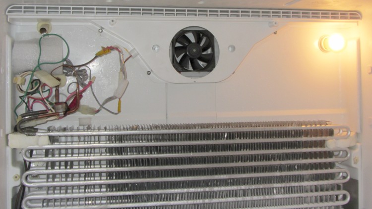
The air flow is toward you out of the screen: the fan draws air from the refrigerator compartment through the evaporator coils, then directly into a square duct that leads back to the refrigerator. Whatever doesn’t make it into the duct flows into the freezer compartment through the row of vents at the top of the picture.
I assume some serious modeling went into choosing the OEM fan blade configuration and spacing so as to optimize the distribution. I hope just moving some air in roughly the right direction will suffice; I have no way to measure any interesting numbers, so this is entirely cut-and-try.
The PC case fan expects 12 VDC, which comes from a standard wall wart conspicuously labeled “For Indoor Use Only”. Well, this is certainly indoor, even if it’s not quite what they expected. The wart plugs into a cobbled-together extension cord receptacle with male 1/4 inch quick-disconnect tabs that match the female QD connectors on the OEM wiring harness that originally plugged into the fan:
PC case fan with adapted wall wart
All that fits into the space behind the rear panel, with the wart wrapped in a sheet of closed-cell foam to prevent rattling and provide a bit of protection:
PC case fan installed in freezer
The rear panel covers the mess, exposing only the row of vent holes along the top. The air flow is upward through the evaporator coil and fins, through the fan, and back to the two compartments.
One question remains: will the fan continue to start below 0 °F (-20 °C)?
Given the ball bearings in the fan, it ought to remain quiet, but I’ve thought that before. Now, however, I have a generous supply of case fans and wall warts that plug into the mechanical and power adapters, so I can replace fans for a long time.
The latch is about the same as before, but the top endplate now has two cable ports and locating pins to take the force from the battery contact springs:
HT-GPS Case – latch detail
The bottom endplate has a hole for the TinyTrak3 Mode switch, plus two locating pins that hold the plate in place:
HT-GPS Case – Wouxun KG-UV3D base view
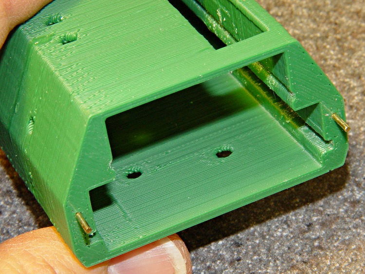
A detail shot of the two endplates shows the new holes:
HT-GPS Case – endplate detail
Snippets of brass rod became locating pins, each slipped into a hole atop a dab of epoxy to lock it in place:
HT-GPS Case – locating pin detail
The boards slide in pretty much the way you’d expect:
HT-GPS Case – Trial fit – rear view
The OpenSCAD code punches a third cable hole in the case for the HT wiring. I had high hopes that it would fit through the endplate, but …
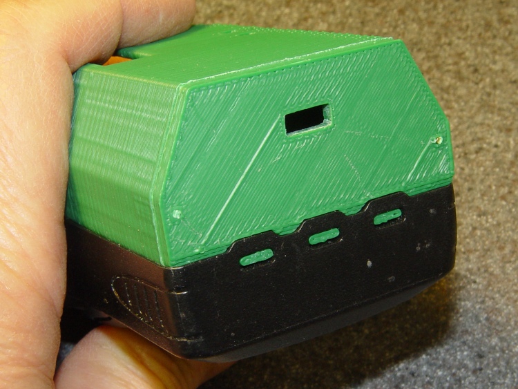
Seen from the other end, there’s not much to see. The next case will have a slightly narrower LED opening:
HT-GPS Case – Trial fit – base view
The imperfection running down the side comes from a brief pause in the proceedings while the support plate fell out of the opening. As a consequence, I discovered that the LED window doesn’t need any support at all.
This view shows one of the battery contacts peeking through the hole for a yet-to-be-made stud:
HT-GPS Case – Wouxun KG-UV3D rear view
The solid model show some additional revisions, but it’s pretty close to the green plastic versions:
HT-GPS Case – holes and pins – solid model
The OpenSCAD source code:
// Wouxun KB-UV3D Battery Pack Case
// Ed Nisley KE4ZNU April 2012

include </home/ed/Thing-O-Matic/lib/MCAD/units.scad>
include </home/ed/Thing-O-Matic/Useful Sizes.scad>

// Layout options

Layout = "Fit";
					// Overall layout: Fit Show
					// Printing plates: Build1 .. Buildn (see bottom!)
					// Parts: TT3 Audio DSub Shell Base Top
					// Shapes: RadioBase Contact
					// Speaker-mic mount: PlugPlate

ShowGap = 20;		// spacing between parts in Show layout

//- Extrusion parameters must match reality!
//  Print with +1 shells and 3 solid layers

ThreadThick = 0.25;
ThreadWidth = 2.0 * ThreadThick;

HoleWindage = 0.2;

function IntegerMultiple(Size,Unit) = Unit * ceil(Size / Unit);

Protrusion = 0.1;			// make holes end cleanly

//----------------------
//- Dimensions

CaseOverallHeight = 31.5;				// from battery surface, must clear PCBs!
CaseOverallWidth = 56;
CaseOverallLength = 80.25;				// inside of base to end of compartment

BatteryClearance = 1.5;					// contact seal height = air gap to compartment

// Interface to radio battery contacts
//	Length = shell length
//		calculated after everything else, so as to fill the compartment

PlateWidthMin = 53.0;
PlateWidthMax = 54.5;
PlateThick = IntegerMultiple(2.0,ThreadThick);
PlateAngle = atan(PlateThick/(PlateWidthMax/2 - PlateWidthMin/2));

ContactDia = 7.0;				// use rounded contact for simplicity
ContactRecess = IntegerMultiple(0.5,ThreadThick);	// recess for contact plate
ContactGapX = 10.5;				// X space between contacts
Contact1Y = 52.5;				// offset from base to edge of contact
Contact2Y = 56.5;
ContactStudDia = Clear4_40;
ContactStudHead = Head4_40;
ContactStudHeadThick = Head4_40Thick;

// Offsets from battery surface to PCB centerlines
//	TT3 must be above HT back shell for DB9 clearance
//	These must cooperate with the numbers in the case shell module

TT3Offset = 17.5 + PlateThick;
AudioOffset = 4.0 + PlateThick;

// Plate interface to base alignment holes and notches

BaseWidthInner = PlateWidthMin;
BaseWidthOuter = CaseOverallWidth;
BaseLength = CaseOverallHeight;					// perpendicular to battery surface
BaseThick = IntegerMultiple(1.0,ThreadThick);	// minimum sheet thickness below teeth
BaseWidthTaper = 5.0;							// ramp across entire width

BaseOpeningMax = 43.0;
BaseOpeningMin = 33.0;
BaseOpeningY = 5.3;
BaseOpeningDepth = IntegerMultiple(2.25,ThreadThick);

BaseTotalThick = BaseThick + BaseOpeningDepth;
echo("Base min thick: ",BaseThick," total: " ,BaseTotalThick);

BaseTabWidth = 6.0;
BaseTabThick = 2.0;
BaseTabGap = 7.0;
BaseTabOC = BaseTabWidth + BaseTabGap;
BaseToothSection = 3*BaseTabWidth + 2*BaseTabGap;

BaseToothBase = 5.8;
BaseToothTip = 2.8;
BaseToothThick = 2.0;
BaseToothAngle = atan(BaseOpeningDepth/0.6);
BaseToothOC = BaseTabOC;

WedgeAngle = atan(BaseWidthTaper/((BaseWidthOuter - BaseWidthInner)/2));

BaseEndLip = ThreadThick;			// should be 0.25 mm or so
BaseEndWidth = (PlateWidthMin - 3*BaseToothBase - 2*BaseToothTip)/2;
BaseEndAngle = atan((BaseOpeningDepth - BaseEndLip)/BaseOpeningY);

SwitchBody = [8.6,3.7,3.3];			// mode switch

// Plate interface to HT battery latch, cables, and connectors

TopThick = IntegerMultiple(5.5,ThreadThick);	// plate thickness for stiffness behind latch bar
echo("Top plate thick: ",TopThick);

DB9Recess = TopThick - 4.0;			// recess to max TT3 PCB clearance behind DB9 plate

TabEngageLength = 1.6;				// tab engaging surface length
TabWidth = 3.0;						//  ... width
TabEngageHeight = 4.5;				//  ... above battery compartment floor
TabHeight = 7.5;					// tab ramp top above battery compartment floor
TabOC = 40.0;

LatchBarWidth = 3.4;				// sliding latch mechanism (brass L stock)
LatchBarDepth = 3.4;
LatchBarThick = 0.35;

echo(" ... minimum: ",TopThick - LatchBarDepth);

SplitOffset = TT3Offset - 3.5;

TopBevel = 1.0;						// bevel at top of battery compartment
TopBevelAngle = 45;

PinOffsetWidth = 2.5;				// choose to center in sides of case shell
PinOffsetHeight = 12.0;				// above baseplate bottom
PinDepth = 7.0;						// into case shell
PinDia = 1.2;

ShellLength = CaseOverallLength - BaseThick - TopThick;

echo("Shell length: ",ShellLength);

// Speaker-mic plug plate

PlugBaseThick = 2.5;				// recess depth
PlugFillThick = 3.0;				// outer plate thickness

//----------------------
// Useful routines

module PolyCyl(Dia,Height,ForceSides=0) {			// based on nophead's polyholes

  Sides = (ForceSides != 0) ? ForceSides : (ceil(Dia) + 2);

  FixDia = Dia / cos(180/Sides);

  cylinder(r=(FixDia + HoleWindage)/2,
           h=Height,
	   $fn=Sides);
}

module ShowPegGrid(Space = 10.0,Size = 1.0) {

  Range = floor(50 / Space);

	for (x=[-Range:Range])
	  for (y=[-Range:Range])
		translate([x*Space,y*Space,Size/2])
		  %cube(Size,center=true);

}

//-------------------
// Component parts

//-----
// TinyTrak3+ PCB and component envelope
//	Some dimensions should feed into the case shell, but don't

module TinyTrak3(Length = 1.0) {

PCBThick = 1.6;
PCBWide = 36.5;
TopHigh = 9.5;
TopWide = PCBWide - 1.5;
BotHigh = 2.5;
BotWide = 35.0;

PCBx = PCBWide/2;
PCBy = (PCBThick + HoleWindage)/2;
URx = TopWide/2;
URy = PCBy + TopHigh;
LRx = BotWide/2;
LRy = PCBy + BotHigh;

  linear_extrude(height=Length,center=false,convexity=2) {
	polygon(points=[[URx,URy],[URx,PCBy],[PCBx,PCBy],[PCBx,-PCBy],[LRx,-PCBy],[LRx,-LRy],
					[-LRx,-LRy],[-LRx,-PCBy],[-PCBx,-PCBy],[-PCBx,PCBy],[-URx,PCBy],[-URx,URy]
				   ]);
  }
}

//-----
// Interface PCB and component envelope
//	Some dimensions should feed into the case shell, but don't

module AudioInterface(Length = 1.0) {

PCBThick = 2.0;
PCBWide = 49.5;
TopHigh = 9.0 + Protrusion;
TopWide = 46.0;
BotHigh = 3.0;
BotWide = 44.0;

PCBx = PCBWide/2;
PCBy = (PCBThick + HoleWindage)/2;
URx = TopWide/2;
URy = PCBy + TopHigh;
LRx = BotWide/2;
LRy = PCBy + BotHigh;

  linear_extrude(height=Length,center=false,convexity=2) {
	polygon(points=[[URx,URy],[URx,PCBy],[PCBx,PCBy],[PCBx,-PCBy],[LRx,-PCBy],[LRx,-LRy],
					[-LRx,-LRy],[-LRx,-PCBy],[-PCBx,-PCBy],[-PCBx,PCBy],[-URx,PCBy],[-URx,URy]
				   ]);
  }
}

//-----
// DB-9 (DE-9) panel opening
// http://www.interfacebus.com/Connector_D-Sub_Mechanical_Dimensions.html
//  DB-9 shell mounts on outside surface of case
// This is for the solder terminal side

module DSubMin9(Length = 1.0) {

Holex = 0.984/2 * inch;
HoleDia = Tap4_40;

URx = 0.769/2 * inch;
URy = 0.432/2 * inch;

	linear_extrude(height=Length,center=false,convexity=3) {
	  polygon(points=[[URx,URy],[URx,-URy],[-URx,-URy],[-URx,URy]]);
	  for (x = [-1,1]) {
		translate([x*Holex,0,0])
		  rotate(45) circle(r=(HoleDia + HoleWindage)/2,$fn=4);
	  }
	}

}

//-----
// Central case shape
//	This *should* depend directly on the circuit board sizes, but doesn't
//	The "Offset" parameters attempt to bottle up all the board sizes
//	Support in LED window must be hand-fit to work correctly... and isn't needed!

module CaseShell(Length=(ShellLength),Holes="true") {

// Polygon coordinates are in XY plane

URx = 40.0/2;
URy = CaseOverallHeight;

MRx = CaseOverallWidth/2;
MRy = 15.0;

LRx = CaseOverallWidth/2;
LRy = (LRx - PlateWidthMin/2)*tan(PlateAngle);

BRx = PlateWidthMax/2;
BRy = PlateThick - 0*Protrusion;

PRx = PlateWidthMin/2;				// combined battery plate
PRy = 0;

ScrewOffset = 20.0;					// from top end of case

LEDWindow = [30.0,5.0,6];			// with case aligned vertically
LEDOffset = [15,URy,(Length + TopThick - 25.0)];

TrimPot1 = [-14,TT3Offset,(Length + TopThick - 30)];
TrimPot2 = [-14,TT3Offset,(Length + TopThick - 37.5)];

HTCableDia = 3.2;
HTCableOffset = AudioOffset + HTCableDia/2 + 1.0;

  rotate([90,0,180])
	union() {
	  difference() {

		  linear_extrude(height=Length,center=false,convexity=5)
			polygon(points=[[URx,URy],[MRx,MRy],[LRx,LRy],[BRx,BRy],[PRx,PRy],
							[-PRx,PRy],[-BRx,BRy],[-LRx,LRy],[-MRx,MRy],[-URx,URy]]);

		if (Holes) {
		  translate([0,AudioOffset,-Protrusion])
			AudioInterface(Length + 2*Protrusion);

		  translate([0,TT3Offset,-Protrusion])
			TinyTrak3(Length + 2*Protrusion);

		  for (y = [TT3Offset,AudioOffset])
			translate([-CaseOverallWidth,y,(Length - ScrewOffset)])
			  rotate([0,90,0])
				rotate(0)					// Z rotation puts point upward for printing
				PolyCyl(Tap4_40,CaseOverallWidth);

		  translate(LEDOffset)
			rotate([90,90,0])
			  translate([-LEDWindow[0]/2,-LEDWindow[1]/2,-Protrusion])
			  cube(LEDWindow,center=false);

		  for (p = [TrimPot1,TrimPot2])
			translate(p)
			  rotate([-90,90,0])				// Y rotation puts point upward for printing
				PolyCyl(3.0,URy);

		  for (x=[-1,1]) {
			translate([x*(CaseOverallWidth/2 - PinOffsetWidth),
					  PinOffsetHeight,
					  (Length - PinDepth)])
			  rotate(45)						// align hole sides with case sides
				  PolyCyl(PinDia,2*TopThick);
			translate([x*(CaseOverallWidth/2 - PinOffsetWidth),
					  PinOffsetHeight,
					  -PlateThick])
			  rotate(45)						// align hole sides with case sides
				  PolyCyl(PinDia,(PlateThick + PinDepth));
		  }

		  translate([-(ContactGapX/2 + ContactDia/2),0,(Contact1Y + ContactDia/2)])
			rotate([90,0,0])
			  Contact();
		  translate([+(ContactGapX/2 + ContactDia/2),0,(Contact2Y + ContactDia/2)])
			rotate([90,0,0])
			  Contact();

		  translate([CaseOverallWidth/2,HTCableOffset,(Length - HTCableDia/2)])
			rotate([0,90,0])
			  cube([(HTCableDia + Protrusion),HTCableDia,CaseOverallWidth],center=true);
		}
	  }

if (false)
	  if (Holes)
		translate(LEDOffset)						// support plug in LED window
		  rotate([90,90,0])
			translate([-0.95*LEDWindow[0]/2,-0.80*LEDWindow[1]/2,ThreadWidth/2])
			  cube([0.95*LEDWindow[0],0.80*LEDWindow[1],2*ThreadWidth],center=false);

	}

}

//-----
// Battery contact recess
//  This gets subtracted from the bottom plate in two places
// 	Align points to print upward

module Contact() {

if (true)
  union() {													// vertical printing with case
	translate([0,0,-(ContactRecess + Protrusion)/2])
	  PolyCyl(ContactDia,(ContactRecess + Protrusion),8);
	translate([0,0,-(PlateThick + Protrusion)])
	  rotate(60/2)
	  PolyCyl(ContactStudDia,PlateThick,6);
	translate([0,0,-(ContactRecess + ContactStudHeadThick/3)])
	  PolyCyl(ContactStudHead,ContactStudHeadThick,8);				// allow for solder blob
  }
else
    union() {												// horizontal printing alone
	translate([0,0,-(ContactRecess - Protrusion)/2])
	  PolyCyl(ContactDia,(ContactRecess + Protrusion),8);
	translate([0,0,-(PlateThick + Protrusion)])
	  PolyCyl(ContactStudDia,(PlateThick + 2*Protrusion));
	translate([0,0,-(ContactRecess + ContactStudHeadThick/3)])
	  PolyCyl(ContactStudHead,ContactStudHeadThick,8);				// allow for solder blob
  }

}

//-----
// Radio bottom locating feature
//  This polygon gets subtracted from the battery pack base

module RadioBase() {

linear_extrude(height=(BaseOpeningDepth + Protrusion),center=false,convexity=5)
  polygon(points=[
			[-BaseOpeningMax/2,-Protrusion],

			[-BaseOpeningMin/2,BaseOpeningY],
			[-(BaseToothOC/2 + BaseToothBase/2),BaseOpeningY],

			[-(BaseToothOC/2 + BaseToothTip/2),(BaseOpeningY - BaseToothThick)],
			[-(BaseToothOC/2 - BaseToothTip/2),(BaseOpeningY - BaseToothThick)],
			[-(BaseToothOC/2 - BaseToothBase/2),BaseOpeningY],

			[ (BaseToothOC/2 - BaseToothBase/2),BaseOpeningY],
			[ (BaseToothOC/2 - BaseToothTip/2),(BaseOpeningY - BaseToothThick)],
			[ (BaseToothOC/2 + BaseToothTip/2),(BaseOpeningY - BaseToothThick)],
			[ (BaseToothOC/2 + BaseToothBase/2),BaseOpeningY],
			[ BaseOpeningMin/2,BaseOpeningY],

			[ BaseOpeningMax/2,-Protrusion],

			[ (BaseTabOC + BaseTabWidth/2),-Protrusion],
			[ (BaseTabOC + BaseTabWidth/2),BaseTabThick],
			[ (BaseTabOC - BaseTabWidth/2),BaseTabThick],
			[ (BaseTabOC - BaseTabWidth/2),-Protrusion],

			[ BaseTabWidth/2,-Protrusion],
			[ BaseTabWidth/2,BaseTabThick],
			[-BaseTabWidth/2,BaseTabThick],
			[-BaseTabWidth/2,-Protrusion],

			[-(BaseTabOC + BaseTabWidth/2),-Protrusion],
			[-(BaseTabOC + BaseTabWidth/2),BaseTabThick],
			[-(BaseTabOC - BaseTabWidth/2),BaseTabThick],
			[-(BaseTabOC - BaseTabWidth/2),-Protrusion],
		  ],
		  convexity=5
  );
}

//-----
// Battery pack base

module Base() {

  difference() {

	rotate([-90,180,0])
	  CaseShell(BaseTotalThick,false);

	translate([0,0,BaseThick])
	  RadioBase();

	translate([-BaseWidthOuter,-(BaseThick + BaseEndLip)/tan(BaseEndAngle),0])
	  rotate([BaseEndAngle,0,0])
		difference() {
		  cube([2*BaseWidthOuter,3*BaseOpeningY,BaseOpeningDepth],center=false);
		  translate([(BaseWidthOuter - (BaseToothSection + 2*Protrusion)/2),0,0])
			cube([(BaseToothSection + 2*Protrusion),1.2*BaseOpeningY,BaseOpeningDepth],center=false);
		}

	translate([0,0,BaseThick])
	  rotate([(-90 + BaseToothAngle),0,0])
		translate([0,-0.5,0])
		  cube([(BaseToothSection + 2*Protrusion),1.0,10],center=true);

	for (x=[-1,1])
	  translate([x*(CaseOverallWidth/2 - PinOffsetWidth),PinOffsetHeight,-Protrusion])
		rotate(45)						// align hole side with plate side
		  PolyCyl(PinDia,2*TopThick);

	translate([(-SwitchBody[0]/2),TT3Offset,-SwitchBody[2]/2])
	  scale([1,1,2])
		cube(SwitchBody);

  }
}

//-----
// Top plate with latch
//	Split around TinyTrak3 serial connector
//	 ... which must be at the same height as in the shell!
//	The cable hole sizes & locations are entirely ad-hoc

module TopPlate() {

Cable1Dia = 5.0;
Cable2Dia = 5.0;
CableHoleLength = TopThick + 2*Protrusion;
CableHoleZ = -Protrusion;

DB9Plate = [32.0,13.5,1.25];					// plate surrounding connector body

  difference() {

	rotate([-90,180,180])
	  CaseShell(TopThick,false);

	translate([0,-TT3Offset,-Protrusion])
	  DSubMin9(TopThick + 2*Protrusion);

	translate([0,-TT3Offset,(TopThick - DB9Plate[2]/2)])
	  cube([DB9Plate[0],DB9Plate[1],(DB9Plate[2] + Protrusion)],center=true);

	translate([-CaseOverallWidth,-SplitOffset,-2*Protrusion])		// split the plate
	  cube([2*CaseOverallWidth,4*Protrusion,(TopThick + 2*Protrusion)]);

	translate([0,0,(TopThick - TopBevel)])
	  rotate([-TopBevelAngle,0,0])
		translate([-CaseOverallWidth,-TopThick,0])
		  cube([2*CaseOverallWidth,2*TopThick,2*TopThick],center=false);

	for (x=[-1,1])
	  translate([(x*TabOC/2),
				(-TabHeight/2 + Protrusion),
				(TopThick - TabEngageLength/2 + Protrusion/2)])
		rotate([90,0,0])
		  cube([TabWidth,
				(TabEngageLength + Protrusion),
				(TabHeight + Protrusion)],center=true);

	translate([-CaseOverallWidth,
			  -(TabEngageHeight + LatchBarWidth - BatteryClearance),
			  (TopThick - LatchBarDepth)])
	  cube([2*CaseOverallWidth,(LatchBarWidth + LatchBarThick),(LatchBarDepth + Protrusion)]);

	for (x=[-1,1])
	  translate([(x*CaseOverallWidth/4),
				-(TabEngageHeight + LatchBarWidth + Clear2_56/2 - BatteryClearance + Protrusion),
				0]) {
		translate([0,0,-Protrusion])
		  rotate(45)						// align sides with slot
			PolyCyl(Tap2_56,(TopThick + 2*Protrusion));
		translate([0,0,(TopThick - LatchBarDepth)])
		  rotate(60)						// align sides with slot
			PolyCyl((Head2_56 + Protrusion),TopThick,6);		// extra extra clearance
	  }

	for (x=[-1,1])
	  translate([x*(CaseOverallWidth/2 - PinOffsetWidth),-PinOffsetHeight,-Protrusion])
		rotate(45)						// align hole side with plate side
		  PolyCyl(PinDia,2*TopThick);

	for (x=[-1,1])						// coincidentally line up with latch tabs
	  translate([(x*TabOC/2),-(SplitOffset - 3.0),-Protrusion])
		scale([1,1.7,1])
		  PolyCyl(Cable1Dia,CableHoleLength,6);
  }

}

//-----
// Speaker-Mic plug mounting plate

module PlugPlate() {

JackOC = 11.20;						// 14.25 OD - (3.58 + 2.58)/2

JackScrewDia = 4.6;
JackScrewOffsetX = 1.00;
JackScrewOffsetY = 5.25;			//  mounting screw to edge of lower recess

PlugBaseWidth = 9.25;				// lower section of plate
PlugBaseLength = 22.0;
PlugBaseRadius = 1.75;

Plug3Offset = 5.25;					// edge of base recess to 3.5 mm jack

Plug2BezelDia = 7.1;				// 2.5 mm plug
Plug2BezelThick = 1.04;
Plug2ScrewDia = 6.0;
Plug3ScrewLength = 3.0;

Plug3BezelDia = 8.13;				// 3.5 mm plug
Plug3BezelThick = 1.6;
Plug3ScrewDia = 7.95;
Plug3ScrewLength = 4.0;

PlugFillOffsetX = JackScrewOffsetX - 0.5;		// base recess CL to fill CL
PlugFillOffsetY = -10.5;				//  ... to edge of fill plate
PlugFillWidth = 11.0;
PlugFillLength = 34.00;
PlugFillRadius1 = 1.5;
PlugFillRadius2 = 4.5;

PlugFillOffsetYTotal = 0;

  BaseX = PlugBaseWidth/2 - PlugBaseRadius;
  BaseY = PlugBaseLength/2 - PlugBaseRadius;

  difference() {
	union() {
	  linear_extrude(height=PlugBaseThick,center=false,convexity=3)
		hull() {
		  translate([-BaseX,-BaseY,0])
			circle(r=PlugBaseRadius,$fn=8);
		  translate([-BaseX, BaseY,0])
			circle(r=PlugBaseRadius,$fn=8);
		  translate([ BaseX, BaseY,0])
			circle(r=PlugBaseRadius,$fn=8);
		  translate([ BaseX,-BaseY,0])
			circle(r=PlugBaseRadius,$fn=8);
		}

	  translate([PlugFillOffsetX,
				(PlugFillLength/2 - PlugBaseLength/2 + PlugFillOffsetY),
				PlugBaseThick])
		linear_extrude(height=PlugFillThick,center=false,convexity=5)
		  hull() {
			translate([0,-(PlugFillLength/2 - PlugFillRadius2),0])
			  circle(r=PlugFillRadius2,$fn=10);
			translate([-(PlugFillWidth/2 - PlugFillRadius1),-PlugBaseLength/2,0])
			  circle(r=PlugFillRadius1,$fn=8);
			translate([-(PlugFillWidth/2 - PlugFillRadius1),
					  (PlugFillLength/2 - PlugFillRadius1),0])
			  circle(r=PlugFillRadius1,$fn=8);
			translate([(PlugFillWidth/2 - PlugFillRadius1),
					  (PlugFillLength/2 - PlugFillRadius1),0])
			  circle(r=PlugFillRadius1,$fn=8);
			translate([(PlugFillWidth/2 - PlugFillRadius1),-PlugBaseLength/2,0])
			  circle(r=PlugFillRadius1,$fn=8);
		  }
	}

	translate([0,-JackOC/2,-Protrusion])
	  rotate(360/16) {
		PolyCyl(Plug3BezelDia,(Plug3BezelThick + Protrusion),8);
		PolyCyl(Plug3ScrewDia,(PlugBaseThick + PlugFillThick + 2*Protrusion),8);
	  }

	translate([0,+JackOC/2,-Protrusion])
	  rotate(360/16) {
		PolyCyl(Plug2BezelDia,(Plug2BezelThick + Protrusion),8);
		PolyCyl(Plug2ScrewDia,(PlugBaseThick + PlugFillThick + 2*Protrusion),8);
	  }

	translate([JackScrewOffsetX,-(PlugBaseLength/2 + JackScrewOffsetY),0])
	  PolyCyl(JackScrewDia,(PlugBaseThick + PlugFillThick + Protrusion));
  }

}

//-------------------
// Build things...

ShowPegGrid();

if (Layout == "TT3")
  TinyTrak3();

if (Layout == "Audio")
  AudioInterface();

if (Layout == "DSub")
  DSubMin9();

if (Layout == "Shell")
  CaseShell(CaseOverallLength);

if (Layout == "Top")
  TopPlate();

if (Layout == "Base")
  Base();

if (Layout == "RadioBase")
  RadioBase();

if (Layout == "PlugPlate")
  PlugPlate();

if (Layout == "Contact")
  rotate([180,0,0])
	Contact();

if (Layout == "Show" || Layout == "Fit") {

  translate([0,-ShellLength/2,0]) {

	translate([0,(Layout == "Show")?-ShowGap:0,0])
	  rotate([90,0,0])
		color("SandyBrown") Base();

	translate([0,0,0])
	    color("Olive") render() CaseShell();

	translate([-(CaseOverallWidth/2 + 10),50,CaseOverallHeight/2])
	  rotate([0,-90,0])
		color("Brown") PlugPlate();

	translate([0,((Layout == "Show")?(ShellLength + ShowGap):ShellLength),0])
	  rotate([-90,0,0])
		color("Chocolate") TopPlate();
  }
}

if (Layout == "Build1") {

  translate([0,-CaseOverallHeight/2,ShellLength])
	rotate([-90,0,0])
		CaseShell();

}

if (Layout == "Build2") {

    translate([5 + CaseOverallHeight,0,0])
	rotate([0,0,90])
	  Base();

  translate([-(5 + CaseOverallHeight),0,0])
	rotate(90)
	  TopPlate();

}

if (Layout == "Build3") {

  translate([0,0,(PlugBaseThick + PlugFillThick)])
	rotate([180,0,0])
	  PlugPlate();

}
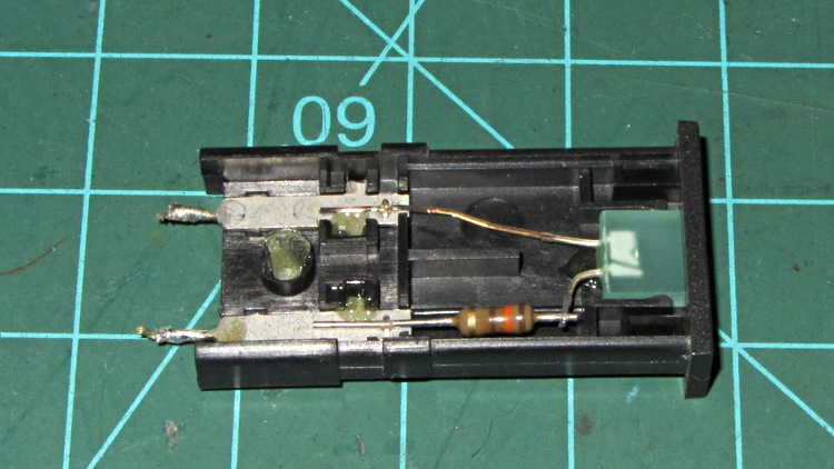
This panel-mount LED indicator glued to the Z-axis stage of my Thing-O-Matic had been dutifully showing a bright green glow when the extruder heater was active:
Failed LED panel indicator
Of late, it began flickering erratically whenever the heater turned on. It used to flicker when the PID loop (hacked to be a bang-bang controller) drove the extruder temperature past the switching threshold, but this was worse.
It’s rated for 5 VDC, 25 mA and has an internal resistor to make that happen. Channeling the true spirit of DIY 3D printer electronics, I deliberately connected it directly across the 12 V extruder power and let it burn at 80 mA. The poor thing was surprisingly bright for an ancient green LED ( the 8124 date code stamped on the side I pried off for the picture says it’s three decades old) and, even under that abuse, it lasted for a year: not to be sniffed at.
I’d expect the LED to fail open when a bond wire burned through, but you just never can tell. It worked fine on the bench, which is typical of all intermittent failures.
So I popped an identical indicator off the stack, conservatively added a 270 Ω series resistor to drop the excess voltage, and it’s all good again.
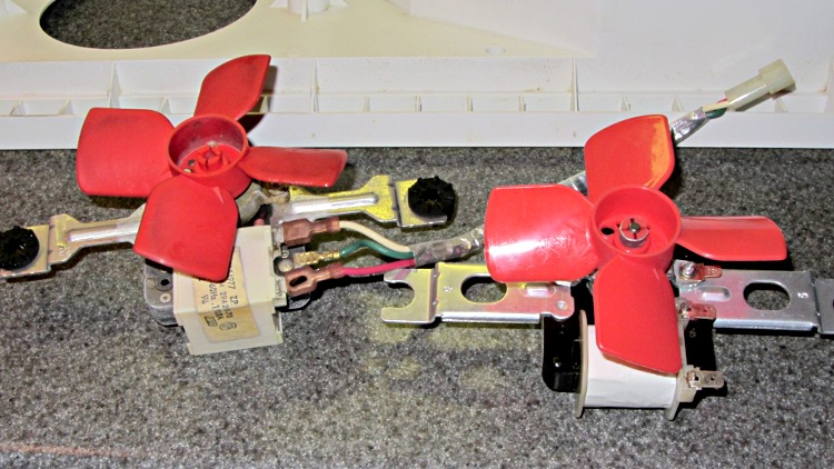
Back in 2006, our ancient (19-ish years old) Whirlpool refrigerator started making weird howling noises suggested someone broke into the house and stuffed a dog inside the freezer. Turned out to be the fan behind the rear panel of the freezer compartment that moves air across the cooling coils and down into the refrigerator compartment; evidently the sintered bronze bearings wore just enough to let the shaft oscillate side-to-side while rotating.
I ordered a replacement, but then decided to try an old fix: put a dollop of STP in the bearings. That added enough damping to kill the resonance and let the old fan turn freely. It worked so well that I put the new fan on the shelf in case it came in handy later on.
Years passed… and then, as if by magic, the freezer dog reappeared.
Mary moved the contents to the downstairs chest freezer (she’s much more organized than I and wanted to find things again), I pulled the old fan out, installed the “new” fan, buttoned up the freezer, and it ran fine.
Whirlpool refrigerator fans
Until about two in the morning, when the freezer dog began howling again…
As nearly as I can tell, the new fan’s bearings arrived just slightly oversize; I doubt they’re pre-worn.
So I applied the STP fix to the new fan:
Remove the compression fitting from the fan blade hub
Remove the fan blades from the shaft
Remove the screws & nuts holding the frame together
Remove motor shaft from bearings
Put a drop of STP into the rear bearing
Slather a ring of STP around the front bearing
Deliberately misalign the self-aligning bearings to redistribute the slack
Reassemble in reverse order
It’s been running silently for a day, which suggests it’ll be good for quite a while…
I finally broke down and bought a Kindle Fire last week, with the intent of having my accumulation of datasheets and manuals where I need them when I need them, and it works reasonably well. One ergonomic blunder: the power button stands just slightly proud of the edge:
Kindle Fire Power Button
That’s exactly where my little finger rests when I’m supporting the slab in my left hand. Past experience has also shown that any opening will admit dust that eventually accumulates behind the screen, so a small protector seemed in order:
Kindle Power Button Protector – solid model
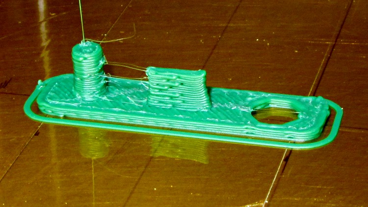
Printed with zero added shells and 1.0 infill produced a solid block of plastic that required very little cleanup:
Kindle power button protector – as built
The zittage serves to improve the fit: the protector should require a bit of fingernail persuasion to remove.
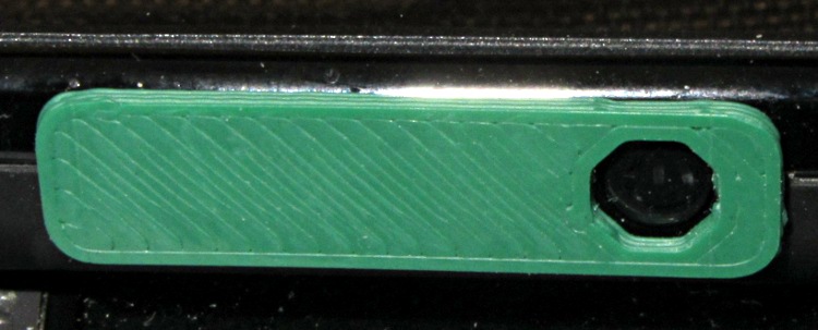
It took two tries to get the Micro-B USB connector slab offset from the centerline just right, but eventually everything lined up correctly:
Kindle power button protector – in place
My pudgy finger squeezes into that opening just enough to turn the thing on and off, but pressing on the green plastic bar has no effect. There’s not enough plastic to allow chamfering the edge in the solid model, but a bit of riffler file action worked wonders on those sharp edges.
The OpenSCAD source code:
// Kindle Fire Power Button Protector
// Ed Nisley KE4ZNU April 2012

include </home/ed/Thing-O-Matic/lib/MCAD/boxes.scad>

//- Extrusion parameters must match reality!
//  Print with +0 shells and 3 solid layers

ThreadThick = 0.25;
ThreadWidth = 2.0 * ThreadThick;

HoleWindage = 0.2;

function IntegerMultiple(Size,Unit) = Unit * ceil(Size / Unit);

Protrusion = 0.1;			// make holes end cleanly

//----------------------
//- Dimensions

PlugDia = 3.5;					// audio jack
PlugLength = 5.0;
PlugOffset = -10;

USBThick = 1.0;					// Micro-B USB jack
USBWidth = 6.8;
USBLength = 4.0;
USBOffset = -0.25;

ButtonDia = 5.2;				// power button
ButtonOffset = 10.0;

PlateWidth = 7.5;
PlateLength = 30.0;
PlateThick = 1.0;
PlateRadius = 2.0;

//----------------------
// Useful routines

module PolyCyl(Dia,Height,ForceSides=0) {			// based on nophead's polyholes

  Sides = (ForceSides != 0) ? ForceSides : (ceil(Dia) + 2);

  FixDia = Dia / cos(180/Sides);

  cylinder(r=(FixDia + HoleWindage)/2,
           h=Height,
	   $fn=Sides);
}

module ShowPegGrid(Space = 10.0,Size = 1.0) {

  Range = floor(50 / Space);

	for (x=[-Range:Range])
	  for (y=[-Range:Range])
		translate([x*Space,y*Space,Size/2])
		  %cube(Size,center=true);

}

//-------------------
// Component parts

//-------------------
// Build things...

ShowPegGrid();

union() {
  translate([PlugOffset,0,0])
	cylinder(r=PlugDia/2,h=(PlugLength + PlateThick),$fn=8);
  translate([0,USBOffset,(PlateThick + USBLength)/2])
	cube([USBWidth,USBThick,(PlateThick + USBLength)],center=true);
  difference() {
	translate([0,0,PlateThick/2])
	  roundedBox([PlateLength,PlateWidth,PlateThick],PlateRadius,true,$fn=4*4);
	translate([ButtonOffset,0,-Protrusion])
	  rotate(360/(2*8))
		PolyCyl(ButtonDia,(PlateThick + 2*Protrusion));
  }
}
I’ve always liked flip-top toothpaste tube caps, which Colgate tubes have and Crest tubes don’t. I’m sure there’s a reason why they use different threads; perhaps there’s a standard for toothpaste tube threads that encompasses both?
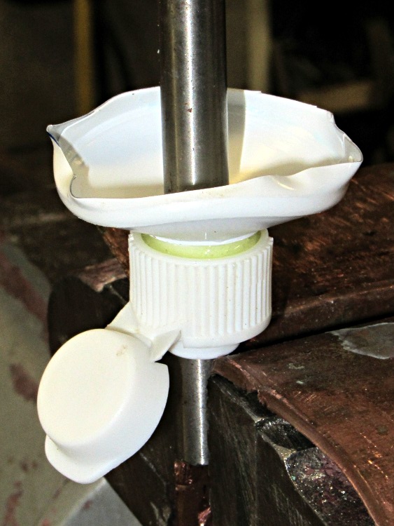
Anyhow, after years of pondering this dilemma, I jammed a Colgate cap and the top of a Crest tube onto a length of 5/16″ drill rod and eased some epoxy into the joint:
Colgate-Crest adapter – gluing
It turns out that the minor diameter of the Colgate cap is just slightly smaller than the major diameter of the Crest tube, so they don’t quite slide together. The epoxy makes for a perfect, zero-clearance fit that’s so tight you must crunch the tube to unscrew it:
Colgate-Crest adapter – thread form
For what it’s worth, that buttress thread form provides a leakproof seal in the original tube.
I have no idea whether this will actually work, because the closet has a three-pack of Colgate that should last for quite a while. Yes, we tend to buy whatever toothpaste seems cheapest on a per unit basis when we’re restocking the closet…
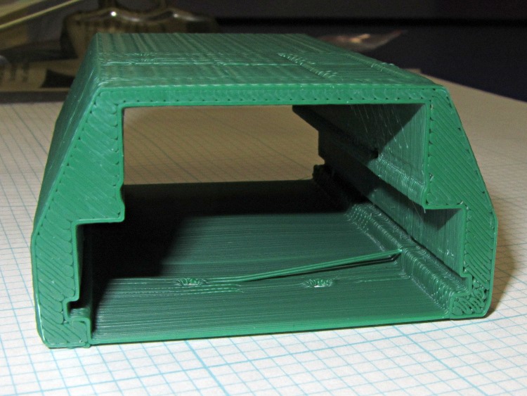
Unlike the previous kludge, this GPS interface case resembles an extrusion with the PCBs sliding into place, held by setscrews along the edges of the slots:
HT-GPS Adapter Case – end view
Those errant threads seem to arise from not quite bonding to the corner. The battery side of the case (bottom in this view) is one thread wide, which isn’t quite enough. Adding another thread makes it 1 mm wide, which seems excessive.
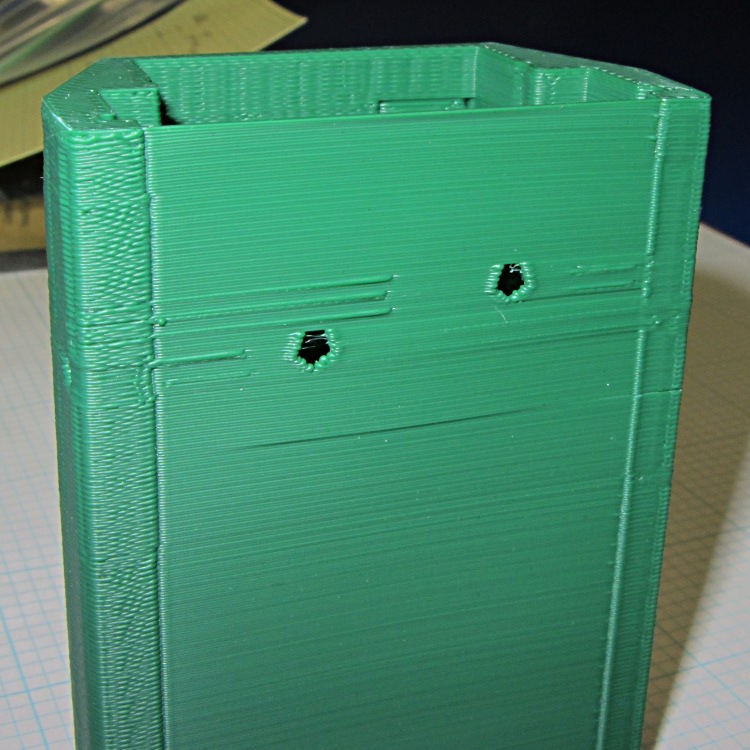
The idea was to glue the battery interface plate on that side, but printing the case vertically puts various flaws along that surface:
HT-GPS Adapter Case – bottom view
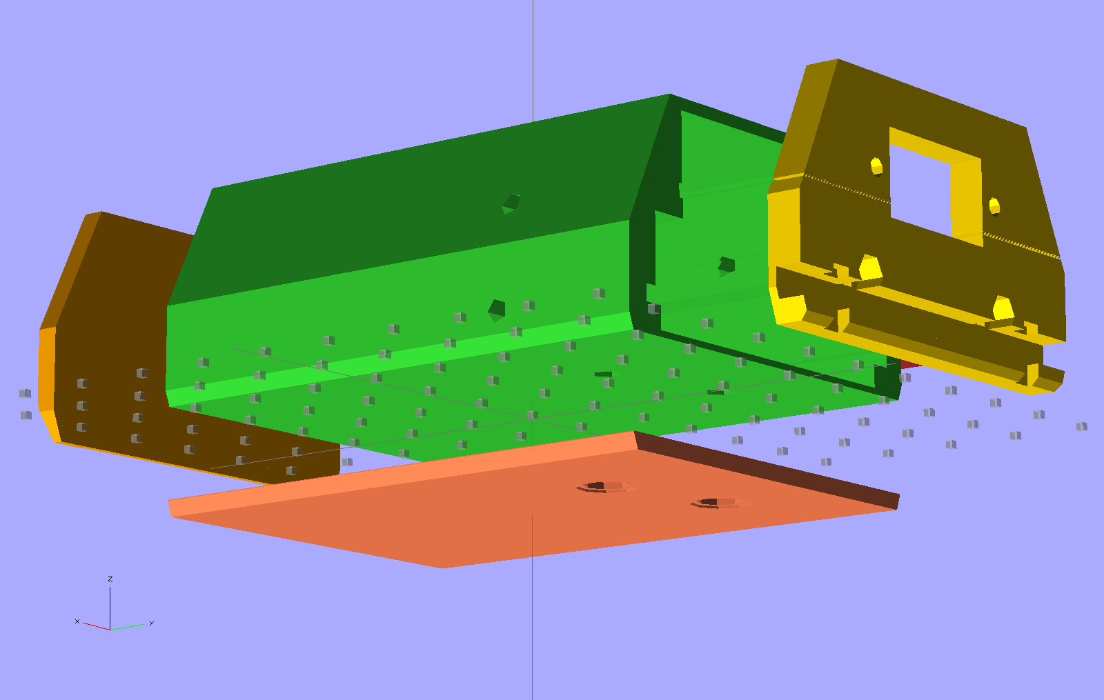
So the next iteration will merge the battery plate with the case and print the whole affair in one shot. This view shows all the parts separately:
HT-GPS Adapter Case – exploded bottom view
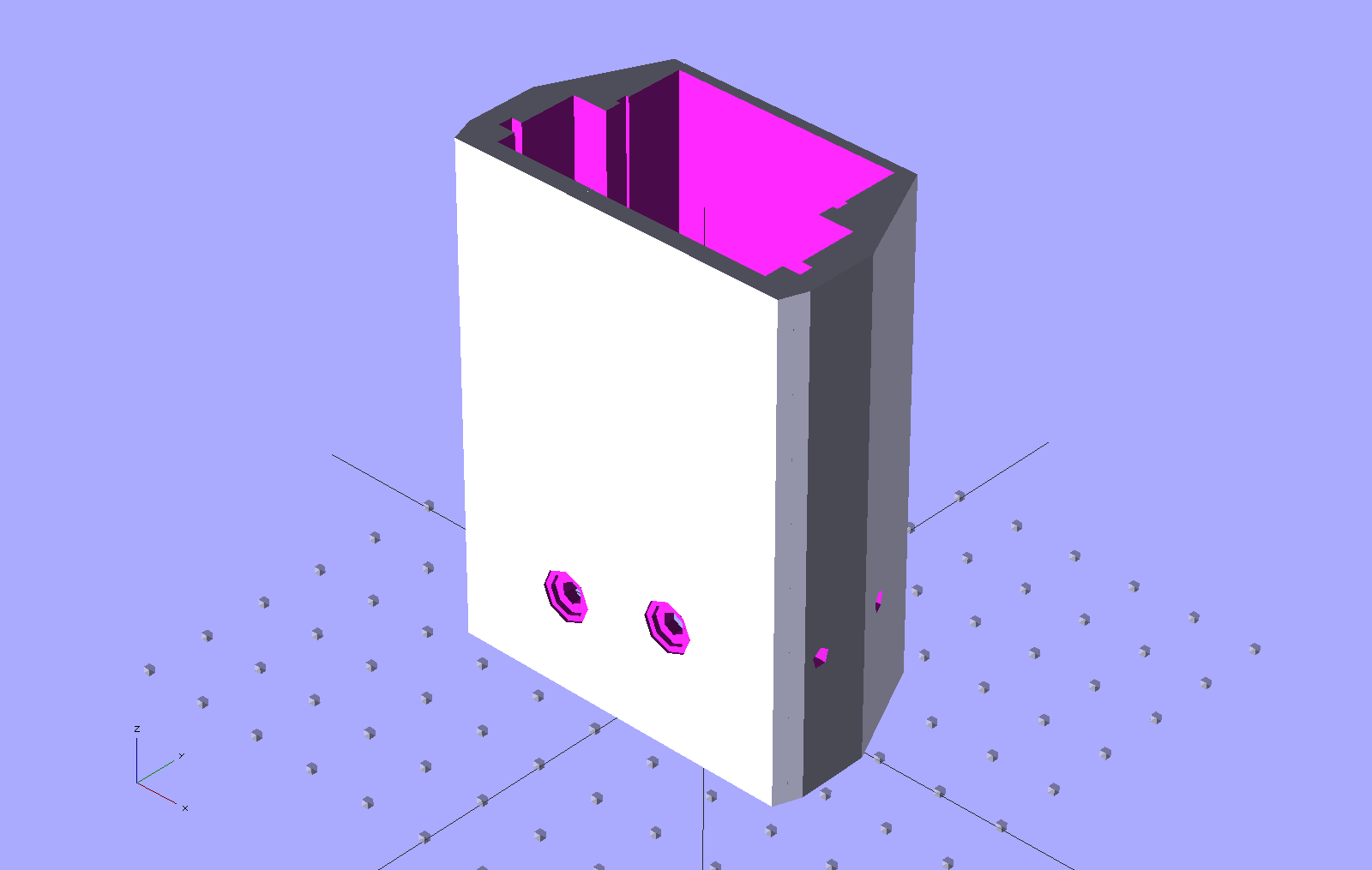
This shows the case joined with the battery plate, neatly aligned for printing:
HT-GPS Adapter Case – combined battery interface
The battery plate has a 0.1 mm extension into the case to avoid problems from objects with coincident planes. Unfortunately, however, that means the intersection between the base plate and the shell forms a line with three planes extending from it: the two outside walls (which are co-planar) and the plate extension inside the case. Skeinforge sometimes complains mightily about that, despite my having applied a union() to fuse the plate with the case: obviously I don’t quite understand how union() works.
I think the battery contact holes will come out close enough to being right; they all have points on the top edge to reduce the overhang problem.
One gotcha: the actual metallic contact studs for the battery. The contacts for the ICOM IC-Z1A case came from carefully shaped brass screws secured by nuts above the PCB and that’s what I’ve been designing around for this case. Unfortunately, the PCB must slide in before installing the studs, which means reaching into the depths of the case, with all the wiring in the way, to turn those nuts. Fortunately, the PCB has plenty of clearance in that direction, but … it’ll be awkward at best.
The studs also need a slot / socket / dingus to prevent rotation while tightening the nuts; right now the contact plate is circular-ish, but maybe I should rethink that.