Collected from various spots around the Web, including evanescent eBay listings, and reformatted to make sense, these specs describe the 2M415 stepper driver: a smaller sibling of the 2M542 family.
Blurb
- +15 to 40VDC Supply Voltage
- H-Bridge, 2 Phase Bi-polar Micro-stepping Drive
- Suitable for 2-phase, 4, 6 and 8 leads step motors, with Nema size 16 to 23
- Output current selectable from 0.21 ~ 1.5A peak
- Compact credit card size package
- Optically isolated single ended TTL inputs for Pulse, Direction and Enable signal inputs
- Selectable resolutions up to 12800 steps
- Over Voltage, Coil to Coil and Coil to Ground short circuit protection.
Electrical specs
| Parameters | Min | Typ | Max | Unit |
| Output Current (Peak) | 0.21 | – | 1.5 | Amp |
| Supply voltage | 15 | 36 | 40 | VDC |
| Logic Input Current | 7 | 10 | 16 | mA |
| Pulse input frequency | 0 | – | 200 | KHz |
| Low Level Time | 2.5 | µsec |
Mechanical specs
| Cooling | Natural Cooling or Forced Convection |
| Space | Avoid dust, oil, frost and corrosive gases |
| Ambient Temp | 0 °C – 50 °C |
| Humidity | 40 – 80 %RH |
| Vibration | 5.9 m/s² Max |
| Storage Temp. | -10 °C – 80 °C |
| Weight | Approx. 150 gram |
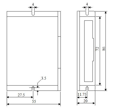
Dimensions
Wiring diagram

Notice that the driver requires a positive voltage for the optoisolators.
Of course, the box from halfway around the planet contained HB-415M drivers. Should you go looking with the usual keywords, you’ll find that HB-number turns up mostly “House Bill number” citations from various state legislatures. Popping the top off the drive reveals www.sikesai.com, which eventually produces a description and PDF datasheet for the driver. It turns out to be an “Ultra Low Noise” driver, whatever that means, with reasonably standard specifications that correspond more-or-less to the 2M415 drivers I thought I was getting.