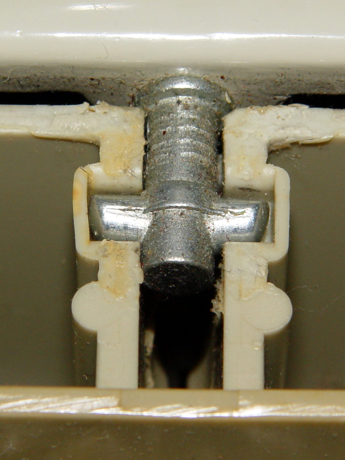
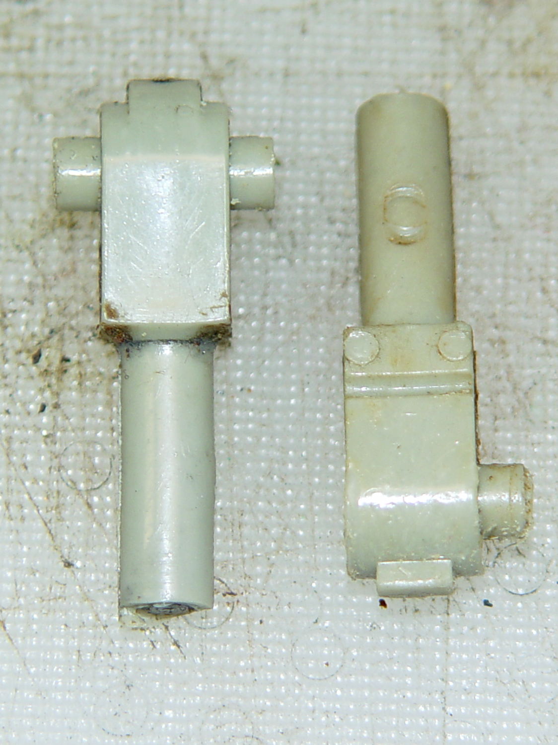
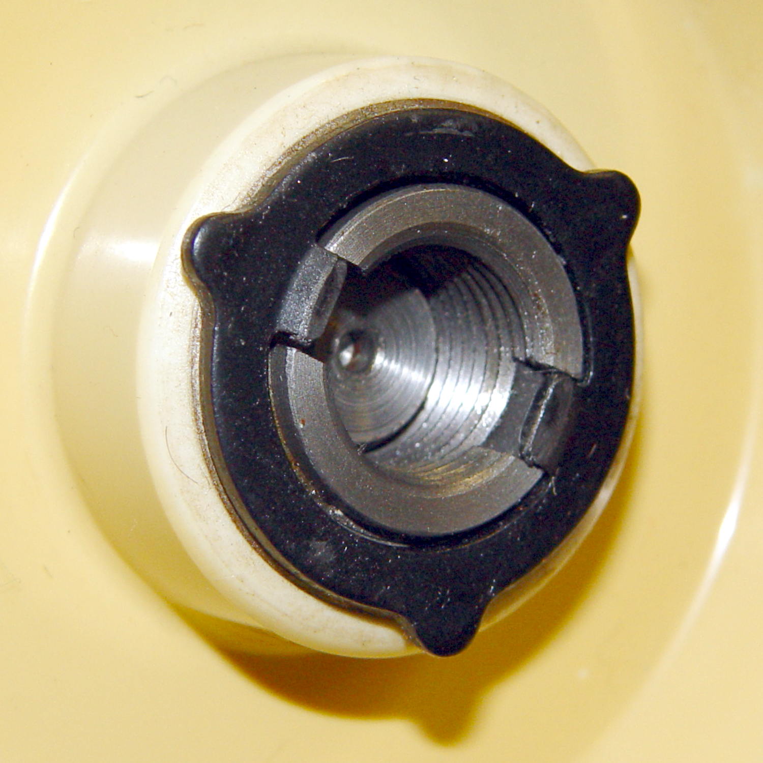
The original foot pedal controlled the sewing machine’s AC motor speed with a carbon disk rheostat:
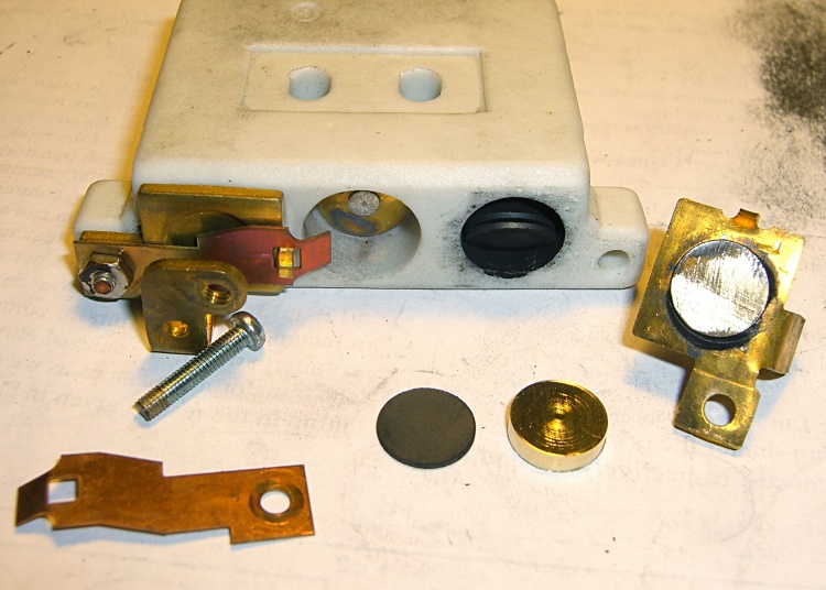
Given the troubles we’ve had with that thing, using it as an input device isn’t going to happen.
More modern “digital” sewing machines seem to use linear potentiometers or analog optical sensors; retrofitting that old housing seems difficult, at best, because the actuator has barely 15 mm of travel. I’m sure somebody could conjure up a bell crank to amplify the mechanical motion, but that ain’t me.
This doodle shows the rudiments of an alternative:

The general idea is to have the existing cross bar / roller move a magnet relative to an analog Hall effect sensor: closer to sensor = higher magnetic field = higher sensor output voltage. Ideally, the magnet provides enough field to max out the sensor just before the pedal reaches the limit of its travel, so the magnet never quite touches the sensor.
An optical wedge would serve a similar function, but this pretty much eliminates all the critical alignment & focusing & friction issues. Plus, I have a bunch of analog Hall effect sensors…
I have a stock of telescoping brass tubing, so the inner tube slides over the 4 mm screw that threads into the existing hardware, replacing the old shaft. That tube slides inside an outer tube that’s aligned in a block attached to the pedal frame; an epoxy blob holds it in position. The inner tube should have a nut on the left end to allow adjusting the rest position.
The Hall effect sensors have a zero-field bias at about VCC/2, so a smaller opposing (and fixed) bias magnet on the far side of the sensor pushes the output voltage to the lower limit. The adjusting screw on that side sets the bias level, if that’s needed.
A spring that’s not shown pushes the cross bar away from the block holding the outer tube and sensor; that’s what restores the magnet to its rest position when the pedal is up.
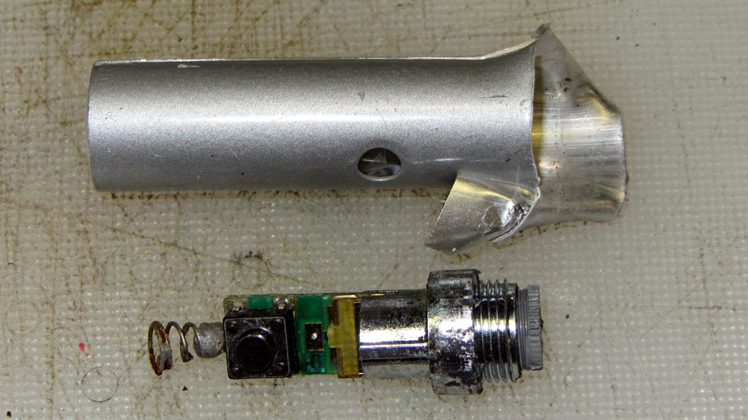
This being the age of rapid prototyping:

The bottom view shows an opening for the epoxy blob halfway between the rear wall and the opening for the magnet and Hall effect sensor:

Two bosses inside the pedal base fit into those rectangular cutouts, with the centerline of the tubing at the top of the bosses.
The inner brass tube holds the outer tube in the proper alignment while the epoxy slab cures:

Fortunately, two of the neodymium magnets in my collection worked out perfectly as the main and bias magnets. The smaller bias magnet just barely saturates the output when epoxied to the back of the sensor and the larger magnet has about 15 mm of active range.
The assembly sequence required half a dozen separate epoxy applications; I used quick-curing clear epoxy, rather than my usual JB Weld, because this isn’t the place for a steel filled epoxy. The final step put a washer on the back of the inner tube to hold the spring in place, with the Hall effect sensor invisible under the wad of closed-cell foam at the bottom:

The spring comes from the Big Box o’ Medium Springs, which contains a few more just like it.
That solid model and the OpenSCAD code below include several refinements that don’t appear in the photos. In particular, the graceful slope on the top front will look a whole lot better than the abrasive adjustment required to fit the chunky first version into the pedal case:

On the other paw, that’s what rapid prototyping is all about. I had no way to measure that dimension, but building one to figure it worked pretty well.
Things that may / will need tweaking:
- The centerline of the tubing lies on the same plane as the tops of the bosses under those three screws, but the bosses are not particularly flat. Perhaps some setscrews to fine-tune the height and front-to-back tilt angle?
- The sketch had adjustable magnet positions; the as-built hardware doesn’t. It’s not clear they’re needed, although that depends on having exactly the right magnets.
- The screws are #4 sheet metal and fit nicely into the metric holes; the original screws held a thin aluminum bracket in place, not that chunky block. I could recess the heads, but …
- A 3D printed clamp holding the cable and strain relief bushing in place would be cuter than the sheet metal strap I bashed from scrap.
The far end of the cable terminates in a 6-pin mini-DIN connector, left over from the days when PCs (remember PCs?) had PS/2 mice & keyboards:
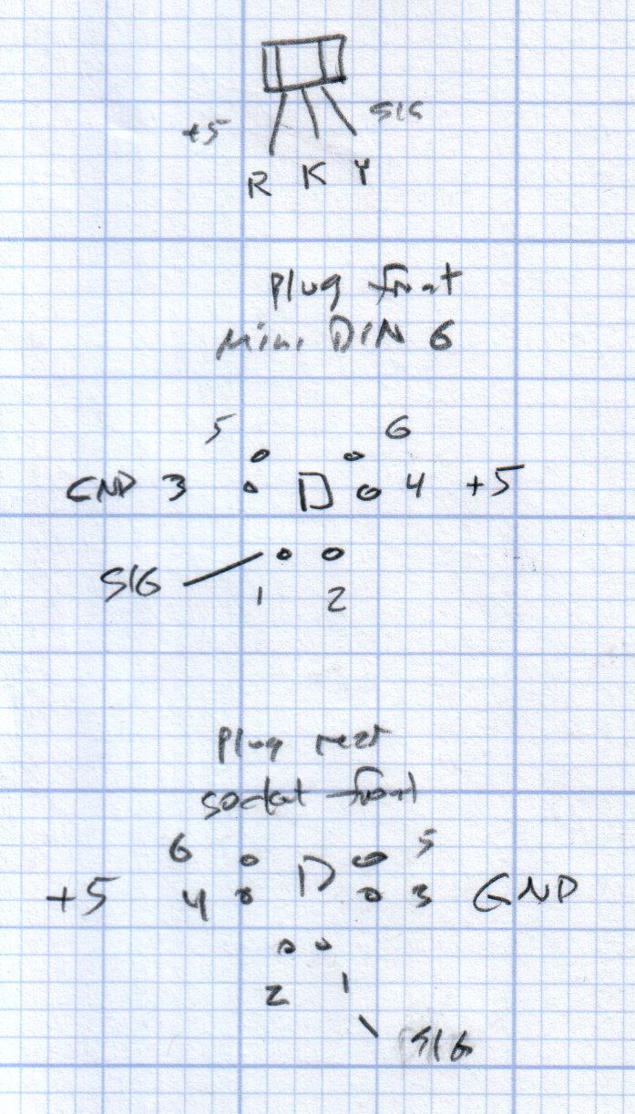
I’ll eventually put the emitter resistor into the circuit; these sensors work fine without it. The cable provides electrostatic shielding and I’m hoping the impedance is low enough that the motor won’t induce any noise. In any event, some low-pass filtering won’t slow down the response enough to notice.
Next, some measurements…
The OpenSCAD source code:
// Foot Control Sensor Mount
// Ed Nisley - KE4ZNU - June 2014

Layout = "Show";			// Plate Build Show

//- Extrusion parameters must match reality!
//  Print with 4 shells and 3 solid layers

ThreadThick = 0.20;
ThreadWidth = 0.40;

HoleWindage = 0.2;			// extra clearance

Protrusion = 0.1;			// make holes end cleanly

AlignPinOD = 1.70;			// assembly alignment pins: filament dia

function IntegerMultiple(Size,Unit) = Unit * ceil(Size / Unit);

//----------------------
// Dimensions
// Origin at center front edge of plate
//  Z = bottom surface

PlateSize = [85.0,53.0,15.0];						// overall plate size
MidZ = PlateSize[2]/2;								//  height of spring midline
PlateCornerRadius = 1.5;

FrontBevel = [0.0,15.0,5.5];						// Y from front, Z from centerline

ScrewHolesOC = [[-75.0/2,(37.0 - 14.0/2)],[-75.0/2,(37.0 + 14.0/2)],[75.0/2,37.0]];
ScrewHoleDia = 4.0;									// allow alignment slop around 3 mm / #4 screws

BossSize = [[12.0,28.0],[12.0,27.0]];				// mounting bosses: L R
BossOC = [[-75.0/2,37.0],[75.0/2,37.0]];

Stroke = 15.0;										// foot pedal actuation distance

Bushing = [5.6,23.0];								// outer brass tube
MainMagnet = [10.0,5.0];							// magnet on pushrod
BiasMagnet = [5.0,2.0];								// bias magnet behind Hall effect sensor
Spring = [9.0,8.0];									// recess for pushrod retracting spring
Washer = [10.0,1.0];								// recess for washer atop pushrod

OD = 0;												// subscripts for cylindrical objects
LEN = 1;

SensorThick = 2.0;									// Hall effect sensor on bias magnet
FilletLength = 0.75;								// glue fillet on main magnet

//----------------------
// Useful routines

module PolyCyl(Dia,Height,ForceSides=0) {			// based on nophead's polyholes

  Sides = (ForceSides != 0) ? ForceSides : (ceil(Dia) + 2);

  FixDia = Dia / cos(180/Sides);

  cylinder(r=(FixDia + HoleWindage)/2,
           h=Height,
           $fn=Sides);
}

module ShowPegGrid(Space = 10.0,Size = 1.0) {

  RangeX = floor(100 / Space);
  RangeY = floor(125 / Space);

	for (x=[-RangeX:RangeX])
	  for (y=[-RangeY:RangeY])
		translate([x*Space,y*Space,Size/2])
		  %cube(Size,center=true);

}

//----------------------
// Basic plate shape

module Plate() {

R = PlateCornerRadius;
Px = PlateSize[0]/2 - R;
Py = PlateSize[1] - R;
Sides = 4*4;

BevelAngle = atan2((MidZ - FrontBevel[2]),FrontBevel[1]);

echo("Bevel angle: ",BevelAngle);

	difference() {
		linear_extrude(height = PlateSize[2]) {
			hull() {
				translate([-Px,Py])
					circle(r=R,$fn=Sides);
				translate([Px,Py])
					circle(r=R,$fn=Sides);
				translate([Px,R])
					circle(r=R,$fn=Sides);
				translate([-(20-R),R])			// avoid left front boss
					circle(r=R,$fn=Sides);
				translate([-Px,20+R])			// avoid left front boss
					circle(r=R,$fn=Sides);
			}
		}

		translate([0,0,-Protrusion])						// screw bosses
			linear_extrude(height = (MidZ + Protrusion),convexity=2)
				for (i=[0:1])
					translate(BossOC[i])
						square(BossSize[i],center=true);

		translate([0,0,-Protrusion])						// plate mounting screws
			linear_extrude(height = 2*PlateSize[2] + Protrusion,convexity=3)
				for (i=[0:2])
					translate(ScrewHolesOC[i])
						rotate(180/6)
							circle(d=ScrewHoleDia,$fn=6);

		translate([0,0,MidZ + FrontBevel[2]])		// Front bevel
			rotate([BevelAngle,0,0])
				translate([0,0,PlateSize[2]])
					cube(2*PlateSize,center=true);

	}
}

//----------------------
// Modify plate for position sensor hardware

module Sensor() {

GluePort = [1.5*Bushing[OD],Bushing[OD]/2,PlateSize[2]];	// port for glue anchor around bushing

MagnetPort = [1.5*MainMagnet[OD],
			  (Stroke + MainMagnet[LEN] + FilletLength + SensorThick),
			  (PlateSize[2] + 2*Protrusion)];

	difference() {
		Plate();

		translate([0,(PlateSize[1] - Bushing[LEN] - Protrusion),MidZ])		// bushing
			rotate([-90,0,0])
				cylinder(d=Bushing[OD],h=PlateSize[1],$fn=6);

		translate([-GluePort[0]/2,										// bushing anchor opening
				  (PlateSize[1] - 0.66*Bushing[LEN] - GluePort[1]/2),
				  MidZ - GluePort[2] + Bushing[OD]/2])
			cube(GluePort,center=false);

		translate([0,(PlateSize[1] - Bushing[LEN] - MagnetPort[1]/2),MagnetPort[2]/2 - Protrusion])
			cube(MagnetPort,center=true);

		translate([0,(PlateSize[1] - Bushing[LEN] - MagnetPort[1] + Protrusion),MidZ])
			rotate([90,0,0])
				PolyCyl(BiasMagnet[OD],BiasMagnet[LEN] + Protrusion,6);

		translate([0,(PlateSize[1] + Protrusion),MidZ])
			rotate([90,0,0]) rotate(180/8)
				PolyCyl(Spring[OD],Spring[LEN] + Protrusion,8);

		translate([0,(PlateSize[1] + Protrusion),MidZ])
			rotate([90,0,0]) rotate(180/8)
				PolyCyl(Washer[OD],Washer[LEN] + Protrusion,8);

	}
}

ShowPegGrid();

if (Layout == "Plate") {
	Plate();
}

if (Layout == "Show")
	Sensor();

if (Layout == "Build") {
	translate([0,PlateSize[1]/2,PlateSize[2]])
		rotate([180,0,0])
			Sensor();
}