The Smell of Molten Projects in the Morning

Ed Nisley's Blog: Shop notes, electronics, firmware, machinery, 3D printing, laser cuttery, and curiosities. Contents: 100% human thinking, 0% AI slop.

Category: Machine Shop

Mechanical widgetry

  • Improved Sony AS30V Helmet Mount Adapter Plate

    Improved Sony AS30V Helmet Mount Adapter Plate

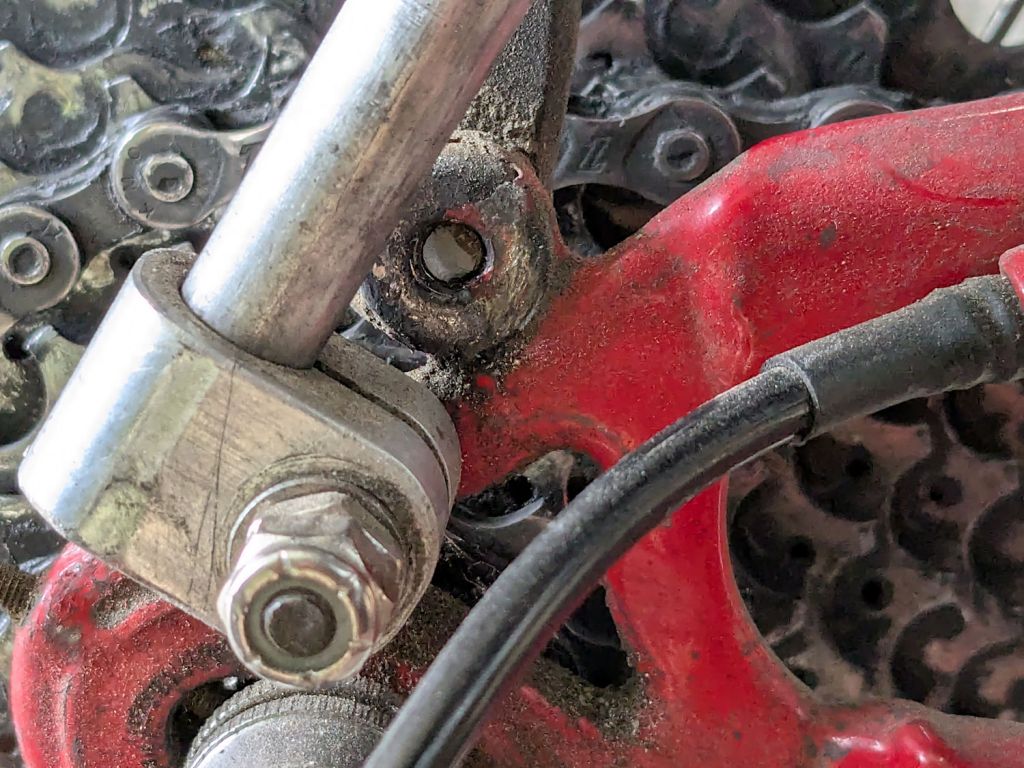
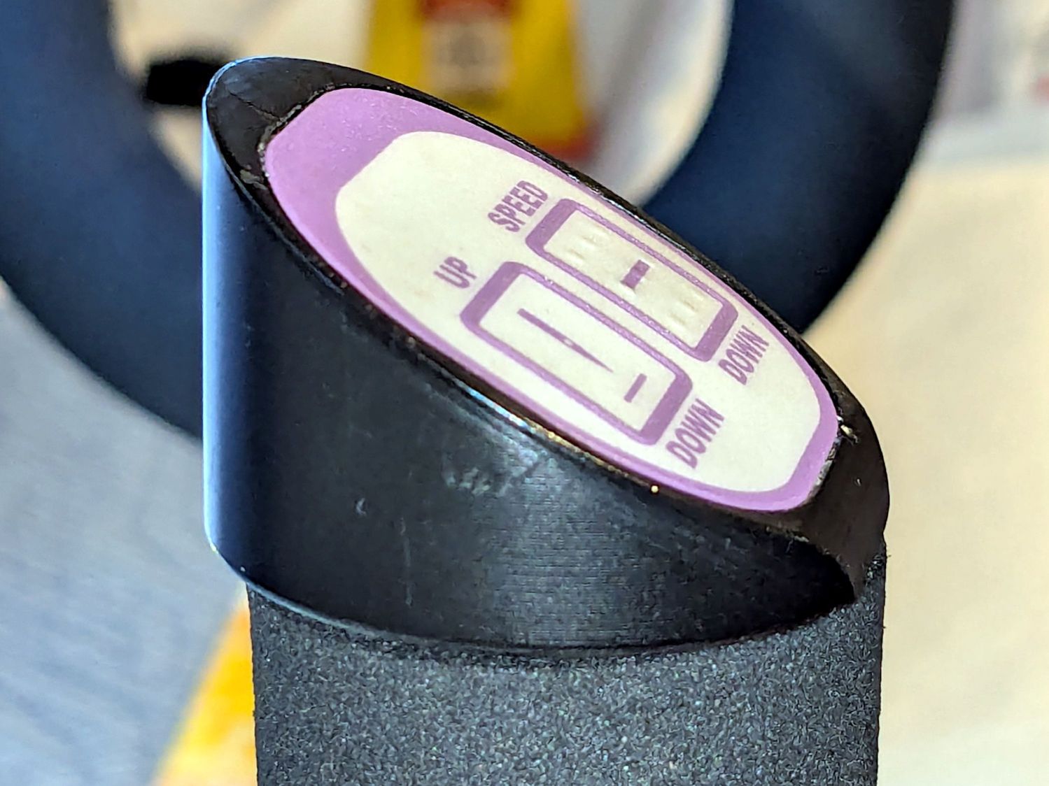
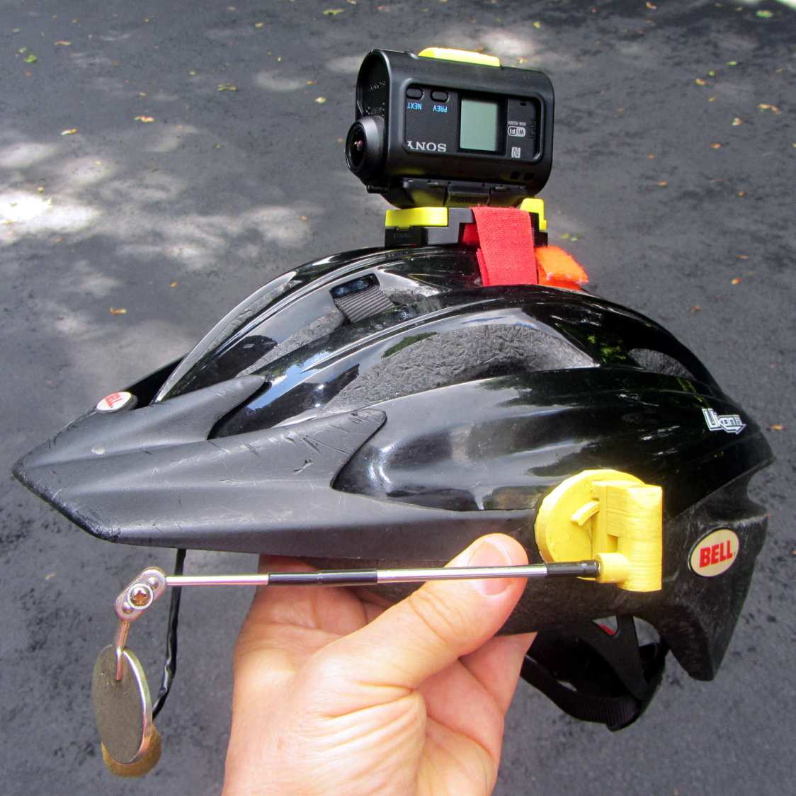
    Last week a wind gust blew my Tour Easy over while resting on its kickstand at Mary’s garden; I rarely depend on the kickstand for that very reason, but some days are like that. Anyhow, the mount for the Sony AS30V helmet camera did exactly what it should by releasing the camera, rather than grinding it into the ground.

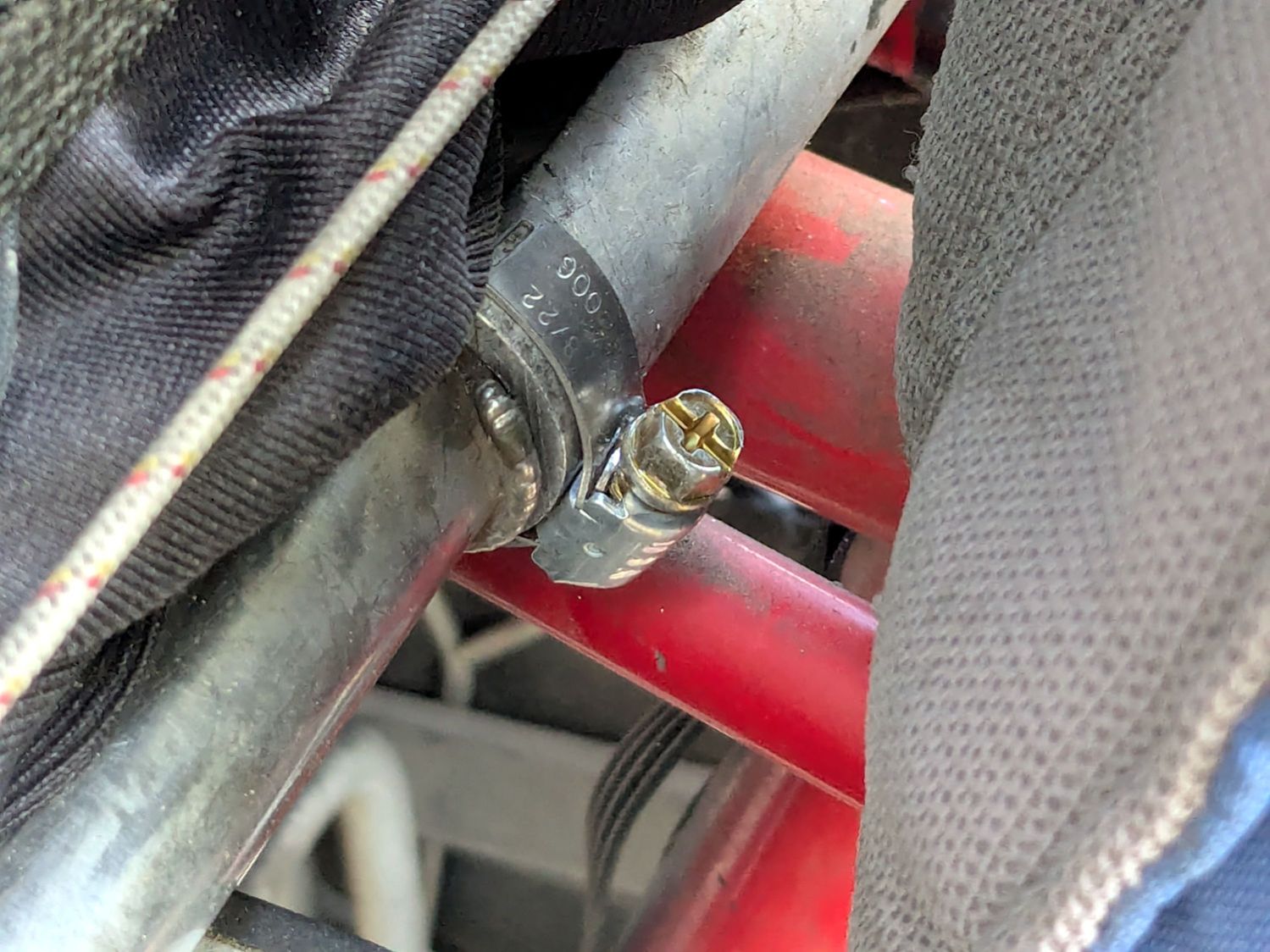
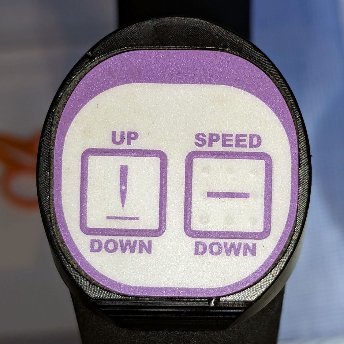
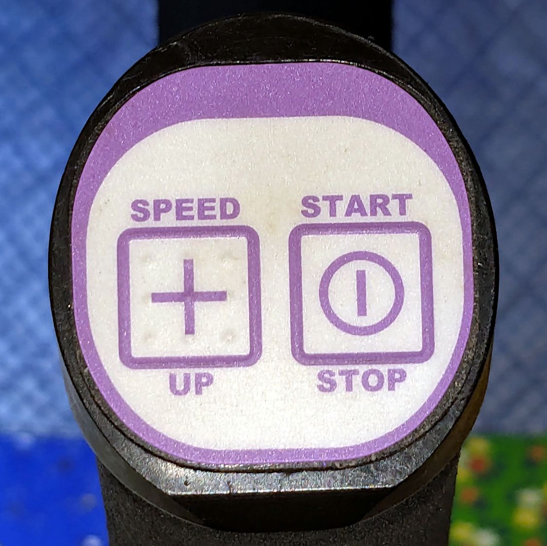
    Calling it a “mount” may be overstating the case:

    Sony HDR-AS30V camera on bike helmet - inverted
    Sony HDR-AS30V camera on bike helmet – inverted

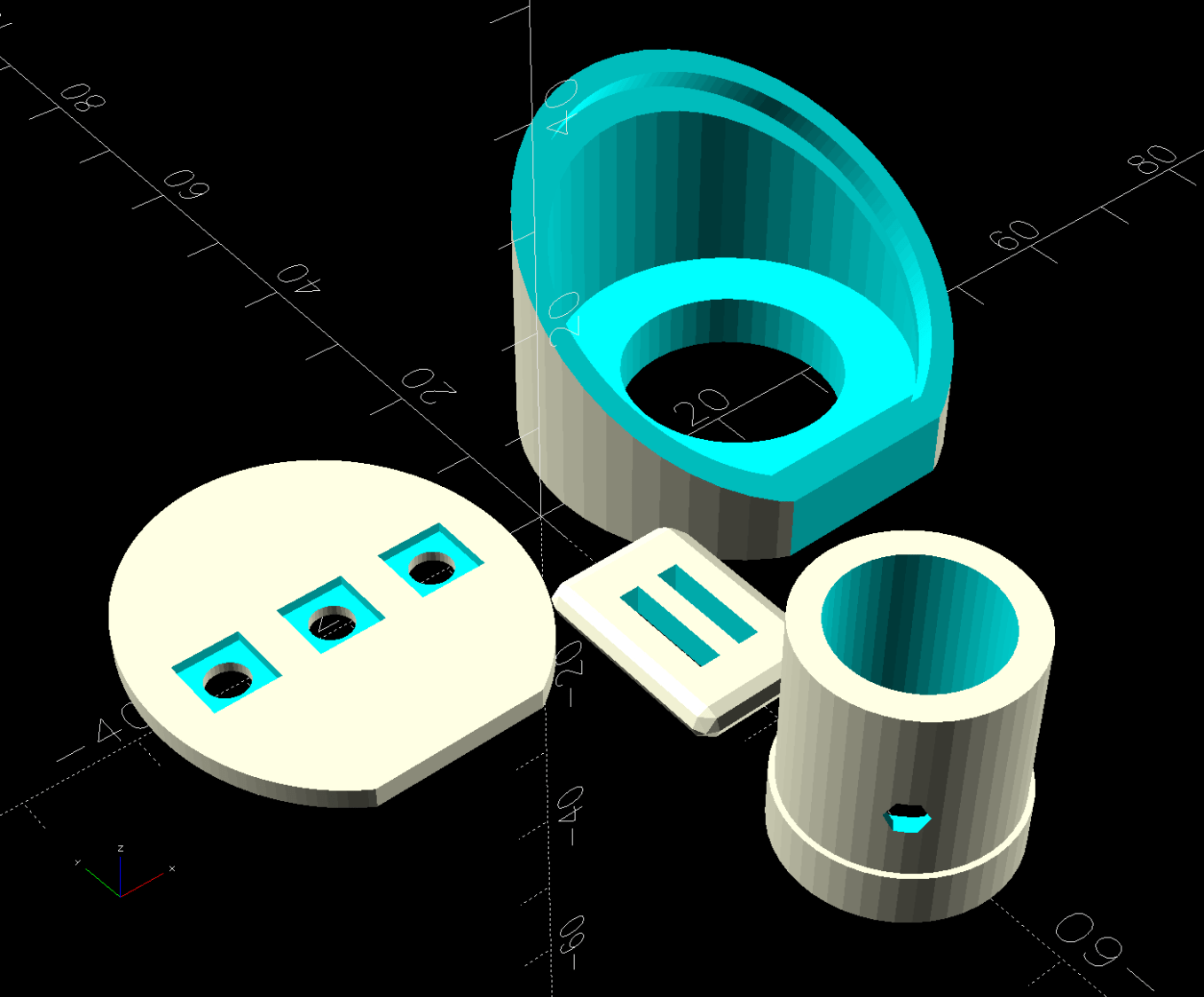
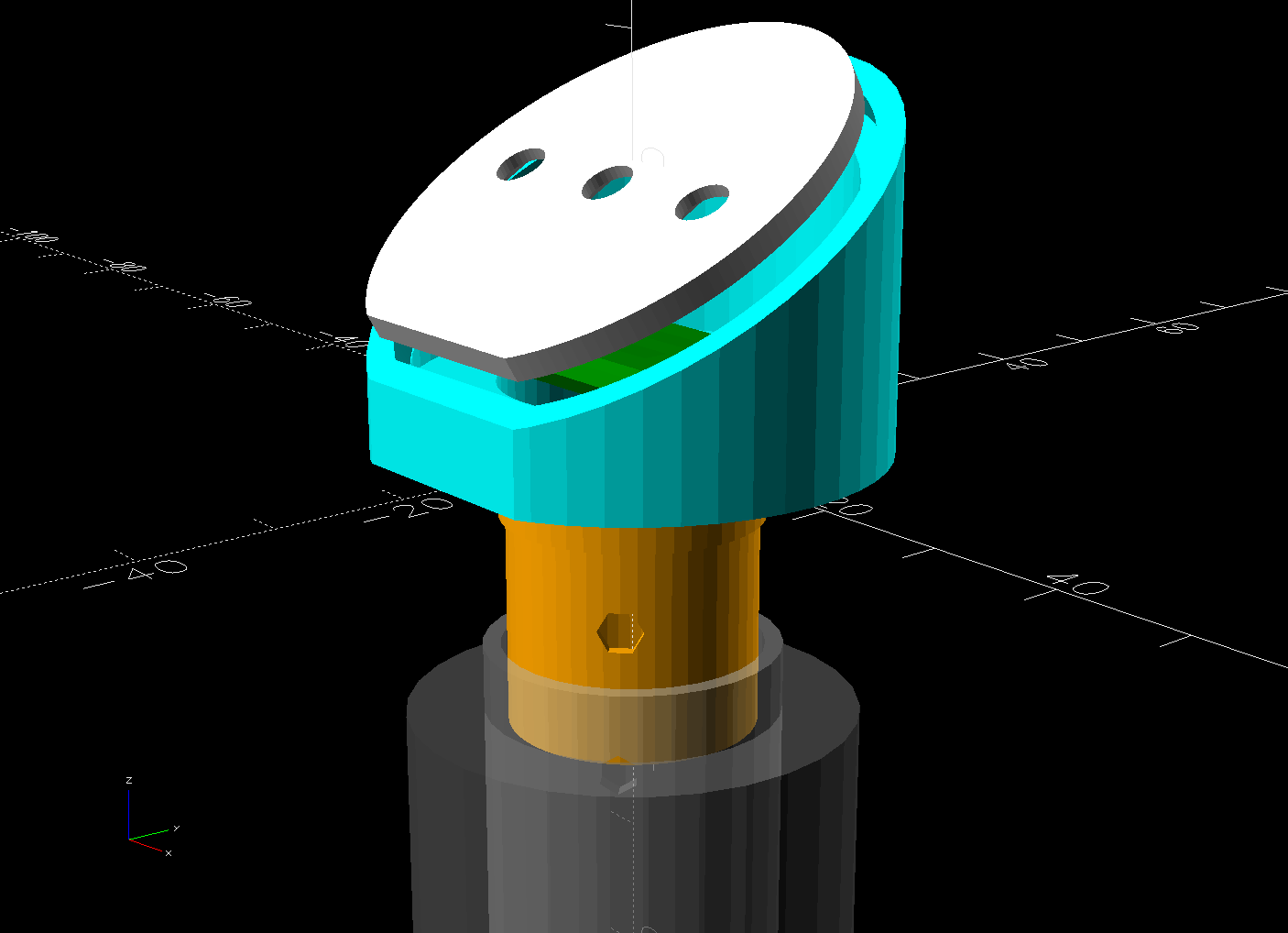
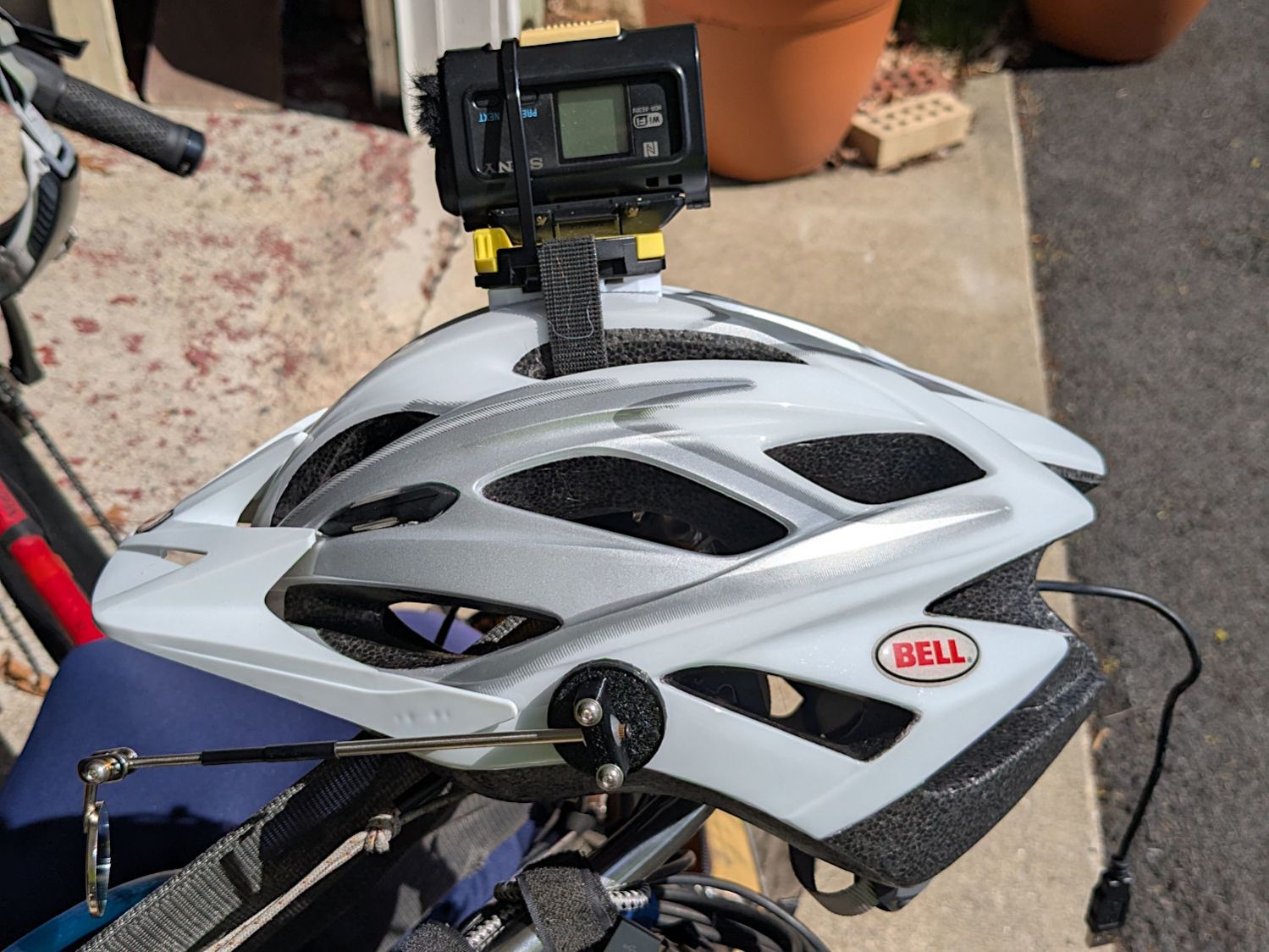
    I was still using that helmet, albeit with a better mirror mount, but it was getting rather crusty and the hook-n-loop straps were definitely sun-faded, so I built a better mount with an adapter plate matching a new-old-stock helmet from the stash:

    Sony AS30V Helmet mount - side view
    Sony AS30V Helmet mount – side view

    The white slab atop the helmet curves to match the helmet contour, with the ridge fitting into the vent slot:

    AS30 helmet mount - solid model - show view
    AS30 helmet mount – solid model – show view

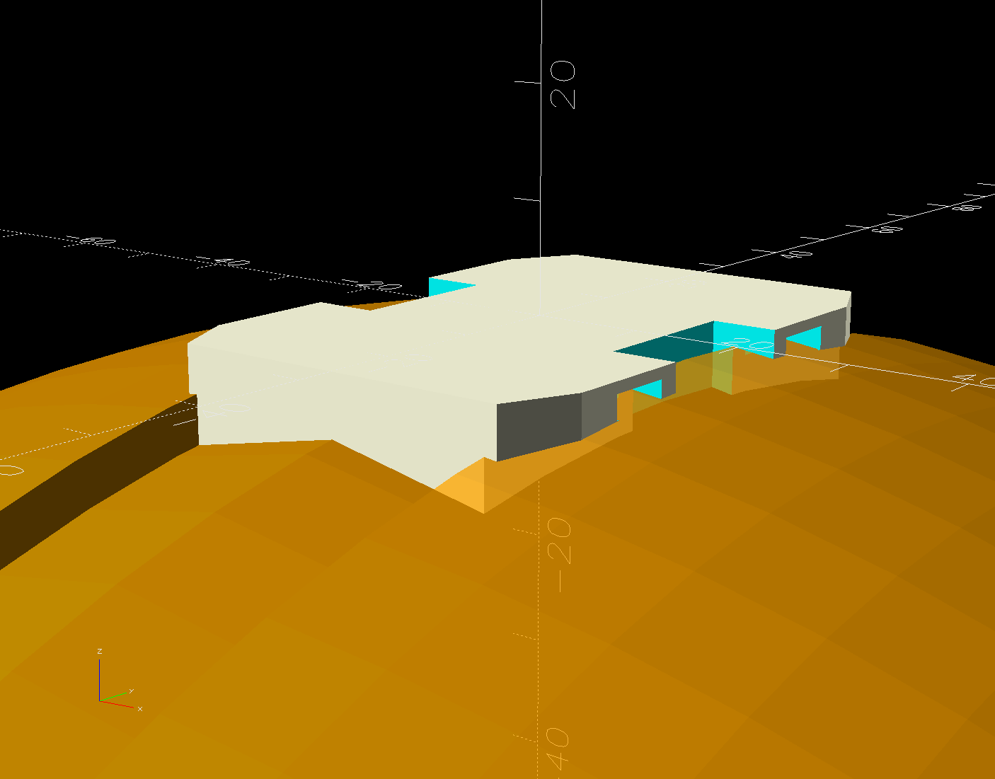
    OK, the helmet isn’t orange, but you get the idea. The sphere has a 153 mm radius, calculated from the Official Sony helmet mount’s bottom curve, minus a ring shaping the central groove:

    AS30 helmet mount - solid model - tab ring
    AS30 helmet mount – solid model – tab ring

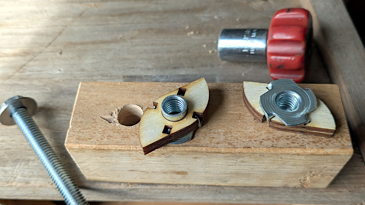
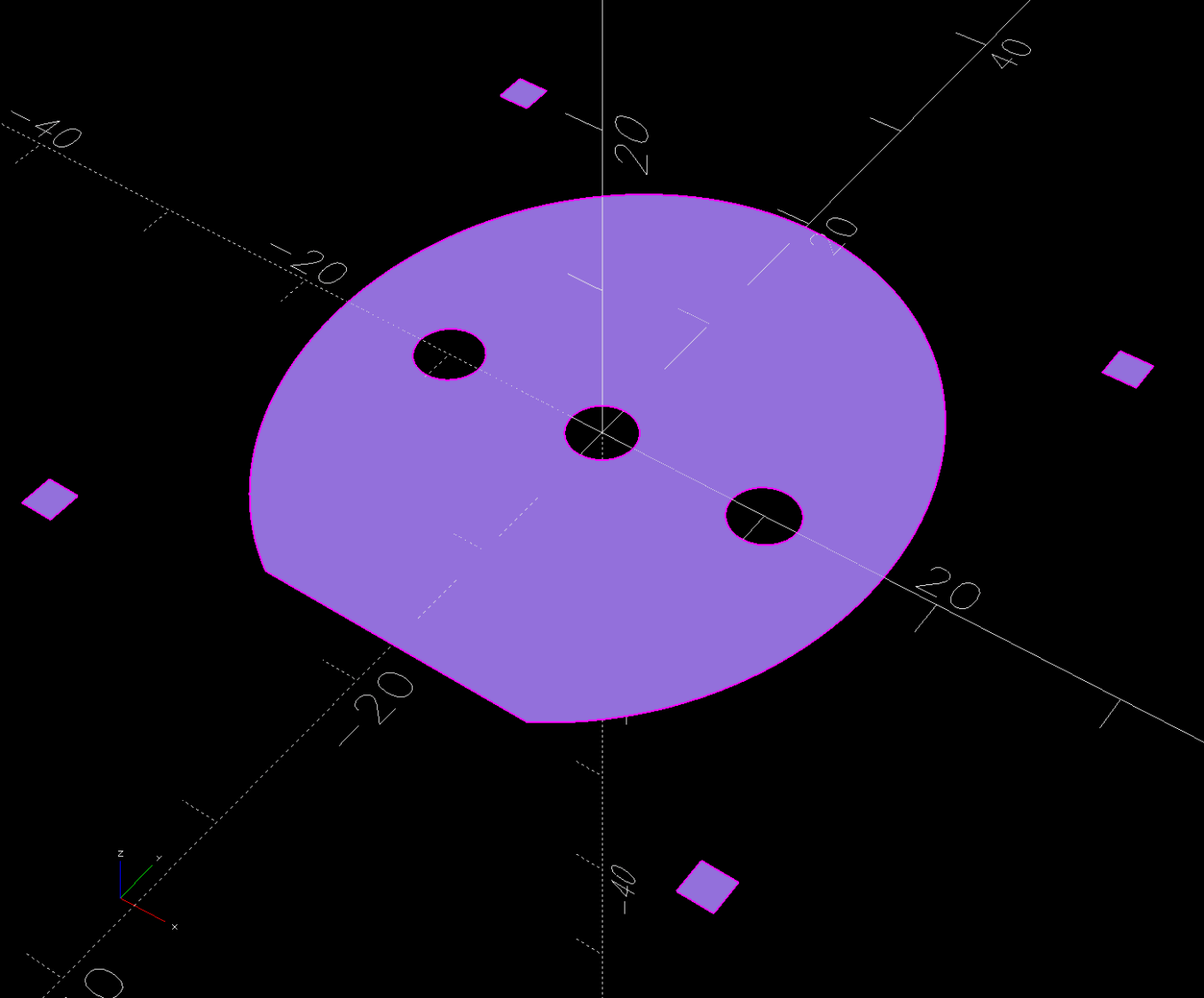
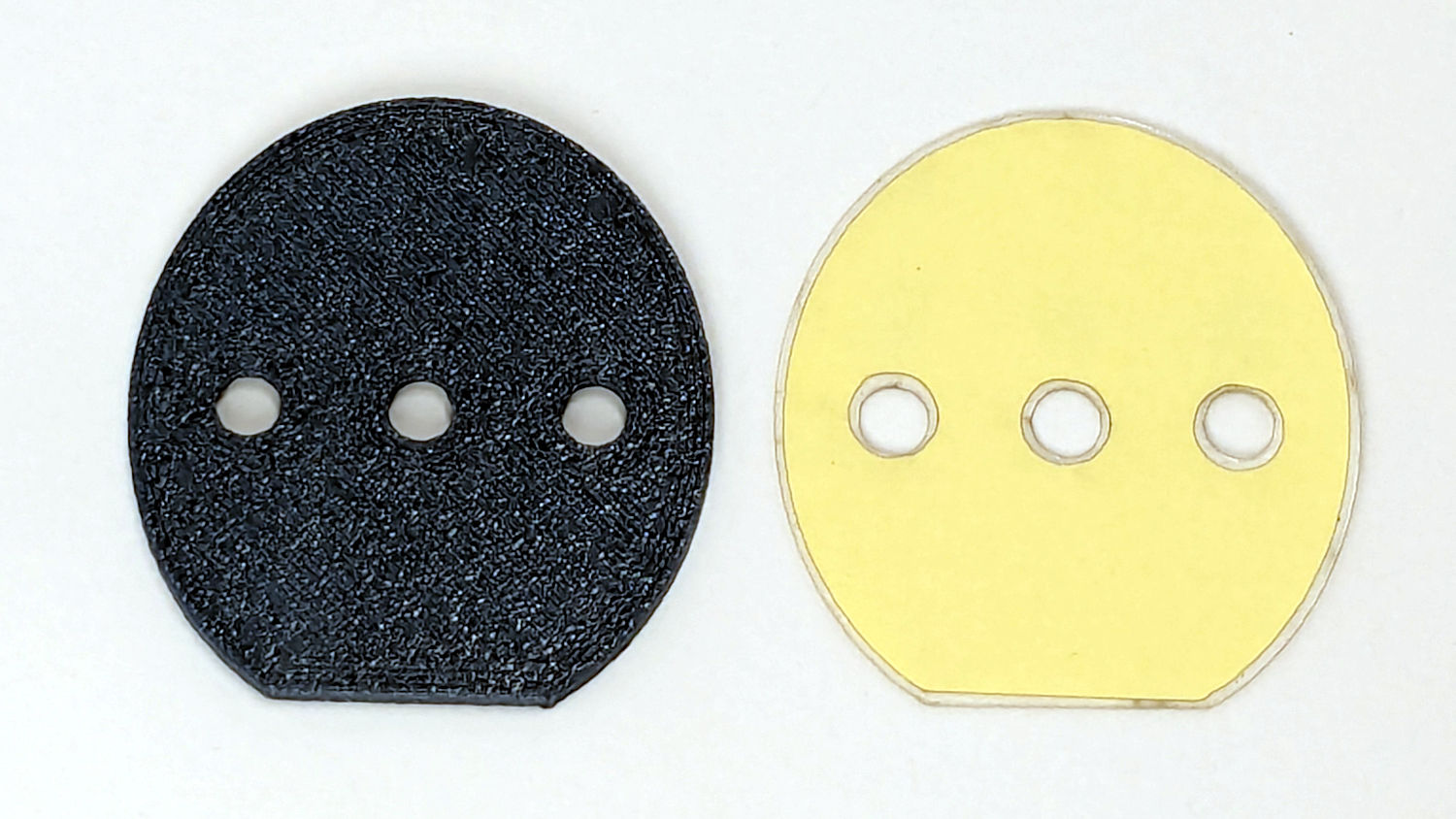
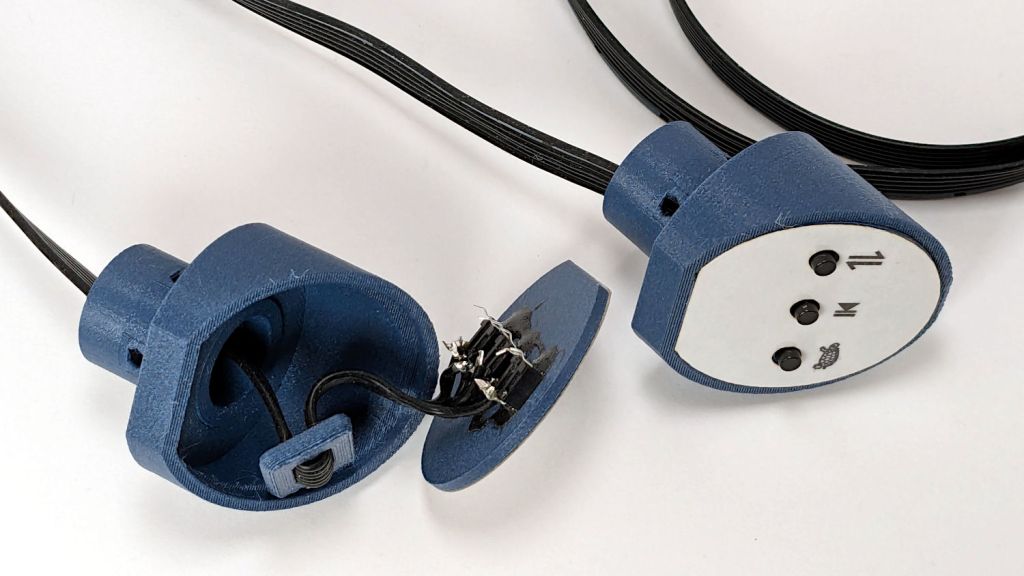
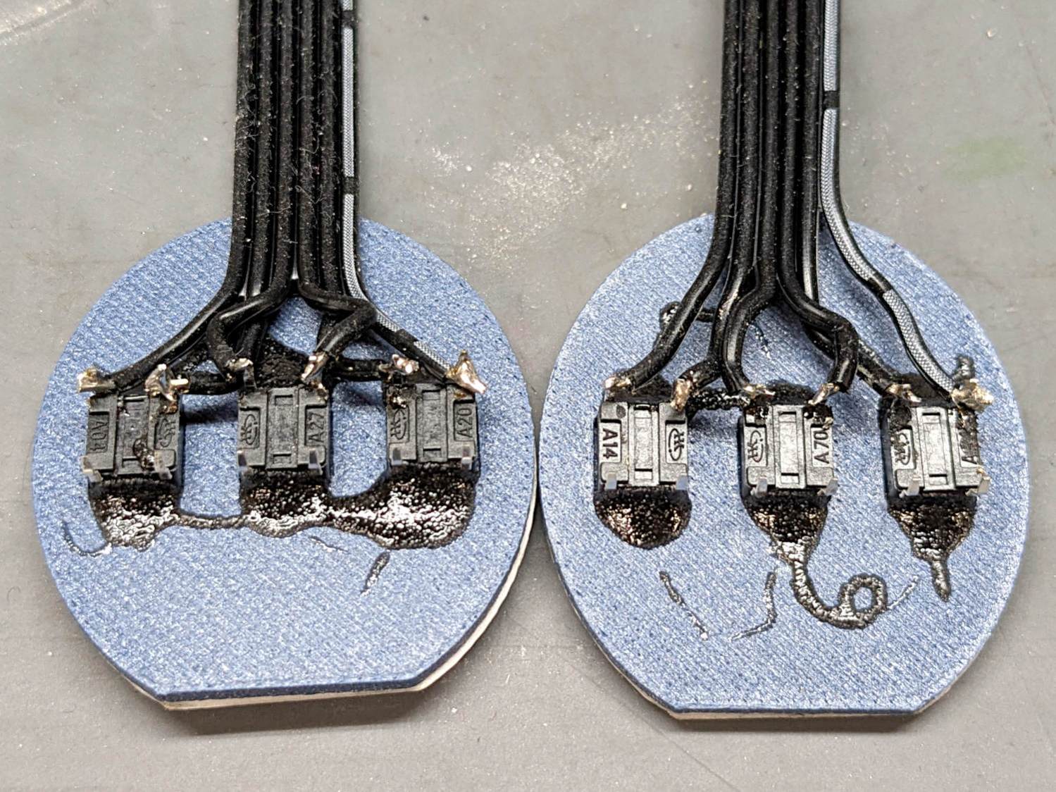
    This upside-down view shows the interesting parts:

    AS30 helmet mount - solid model
    AS30 helmet mount – solid model

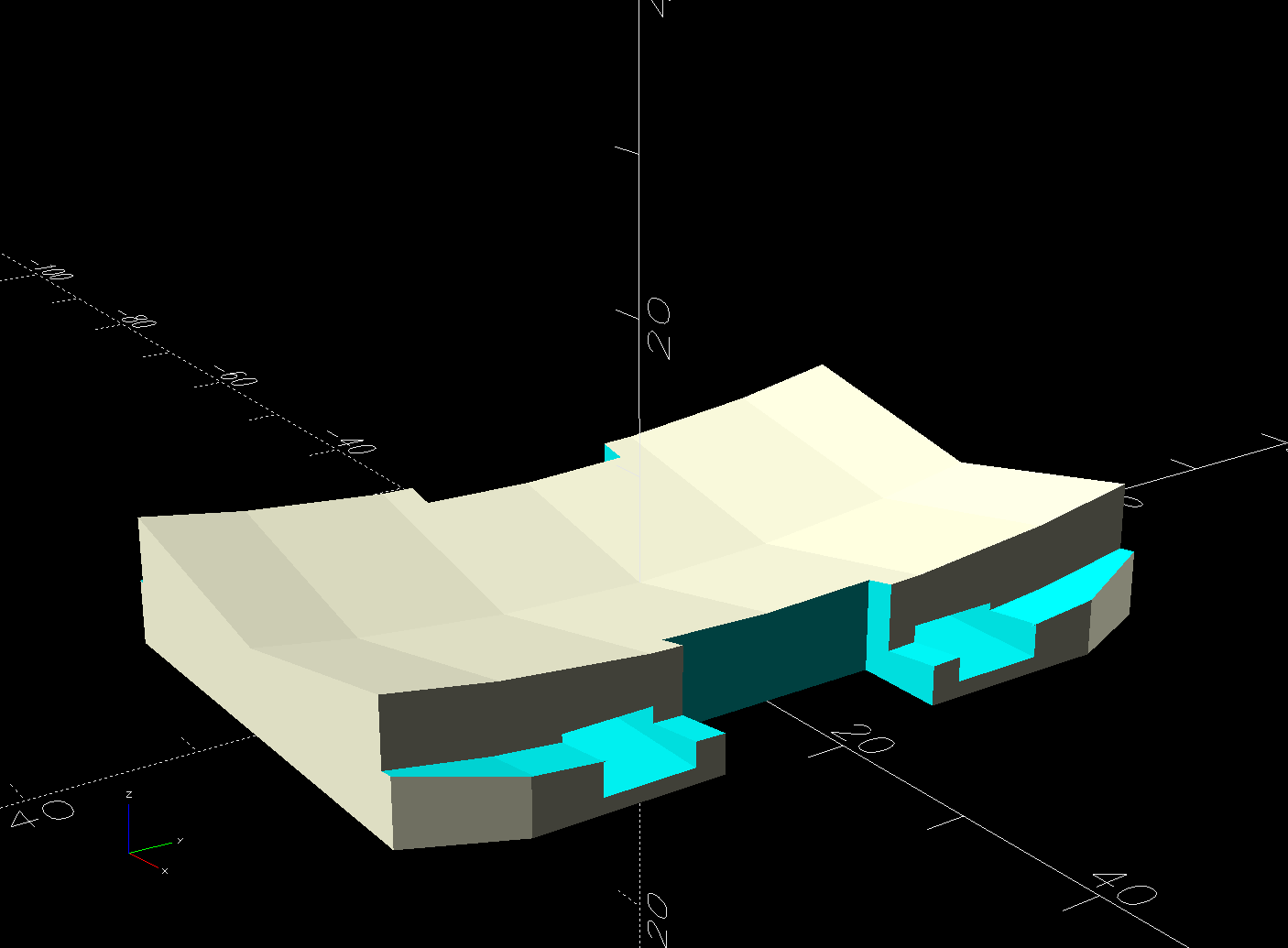
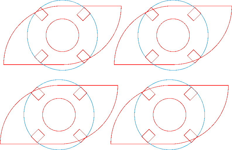
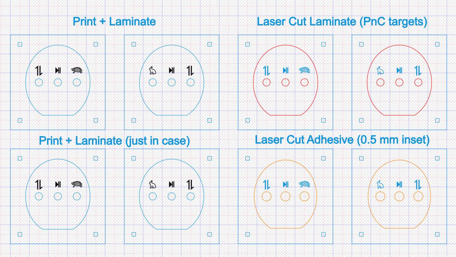
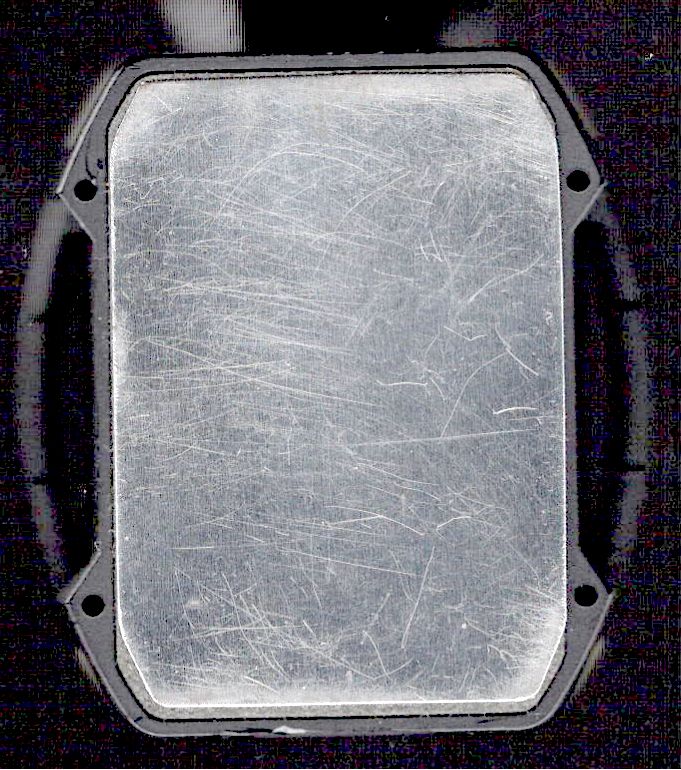
    The flat side sticks to the camera’s holder with a custom-cut sheet of craft adhesive shaped like this:

    AS30 helmet mount - glue
    AS30 helmet mount – glue

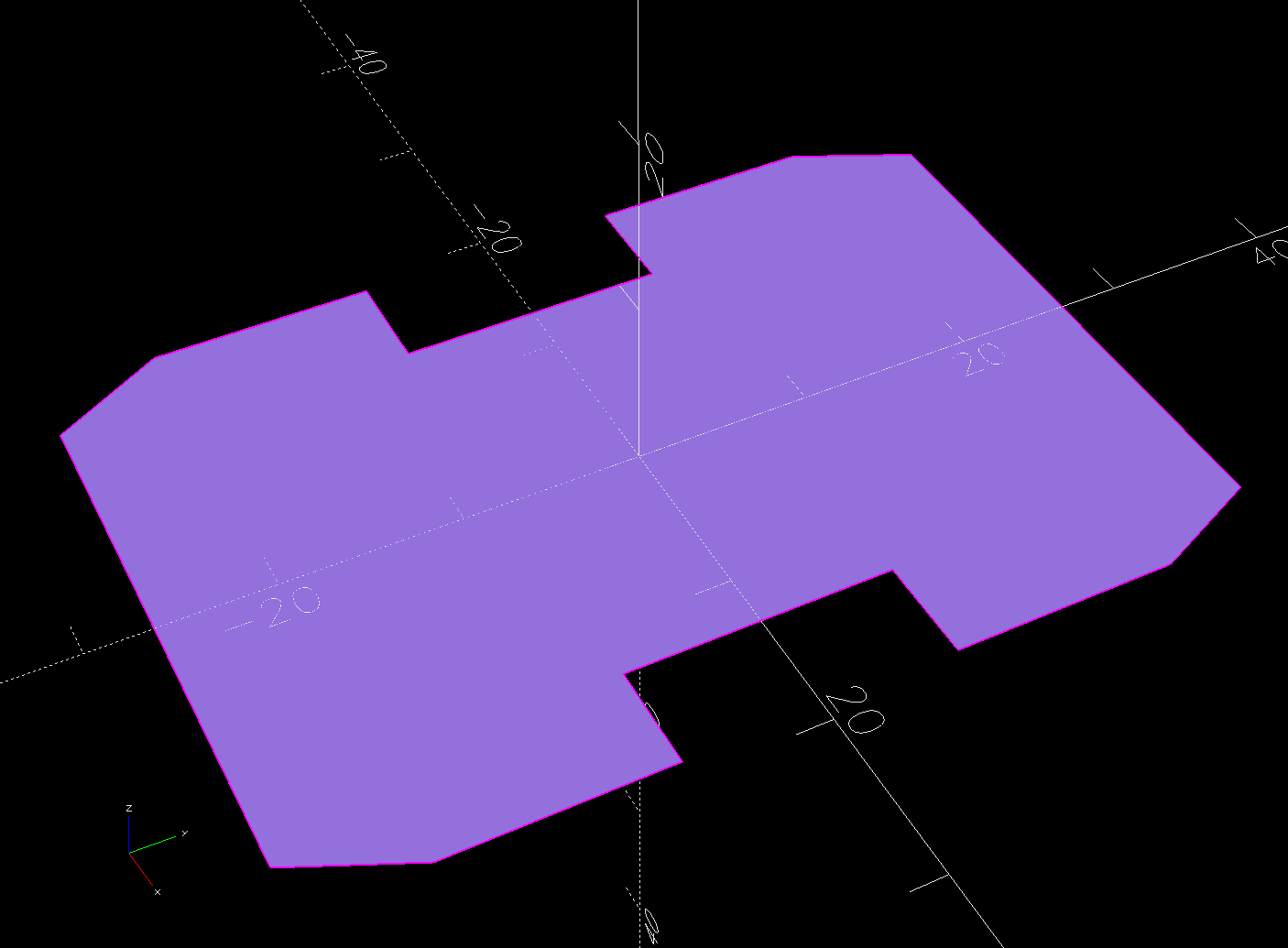
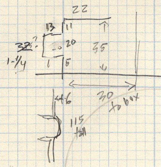
    The overall outline of those things comes from a scan of the bottom of the Sony camera holder, passed through Inkscape and LightBurn to generate the curves:

    AS30 Baseplate scan
    AS30 Baseplate scan

    The large notches in the sides pass hook-n-loop straps intended to break away when the helmet hits the ground again. The front tunnel (of two, because symmetry) passes a cable tie preventing the camera from parting company with the mount during normal riding and holding the yellow latch in the Locked position:

    Sony AS30V Helmet mount - rear view
    Sony AS30V Helmet mount – rear view

    It is just barely possible to slide the cable tie over the front of the camera to release the latch.

    The camera rides upside-down to protect the lens from scuffs and scrapes. Fortunately, there’s a setting to invert the picture.

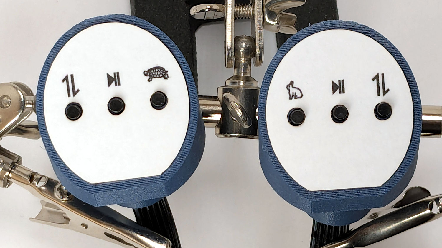
    For completeness, the front view:

    Sony AS30V Helmet mount - front view
    Sony AS30V Helmet mount – front view

    The furry patch covers the microphone pores to kill (most of) the wind noise.

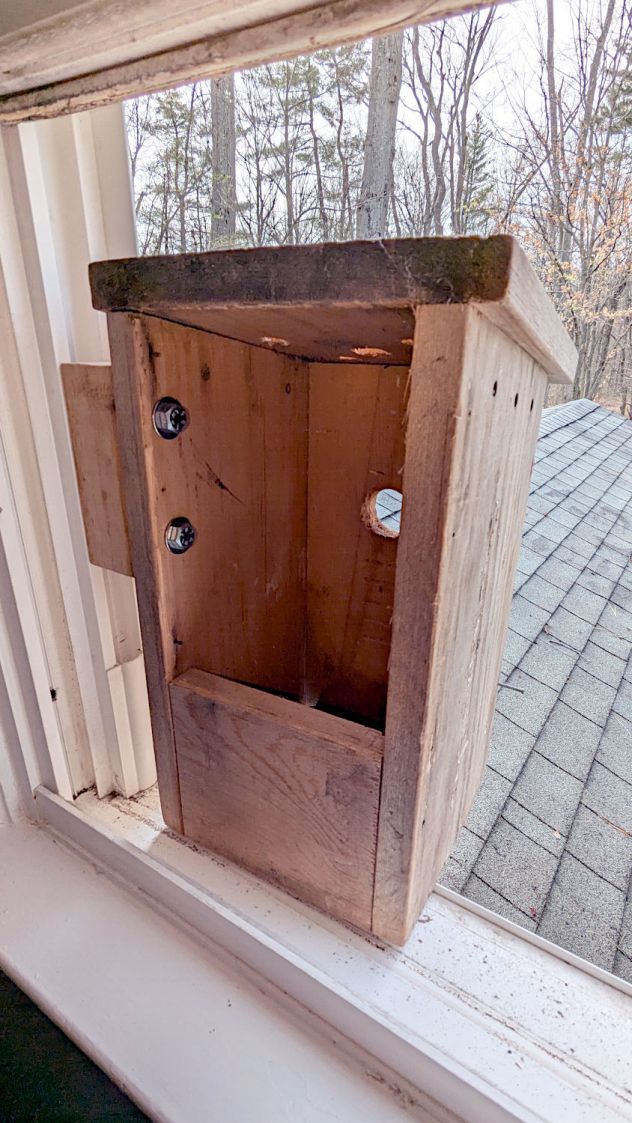
    The sharp ventral angle matches the helmet’s midline ridge in the back, but obviously isn’t needed over the vent hole in the front. I decided to not bother making a comprehensive model of the hole, not least because I didn’t really know the camera’s exact front-to-back location.

    Works fine where it sits, though:

    Burnett Signal Timing - 2025-04-23
    Burnett Signal Timing – 2025-04-23

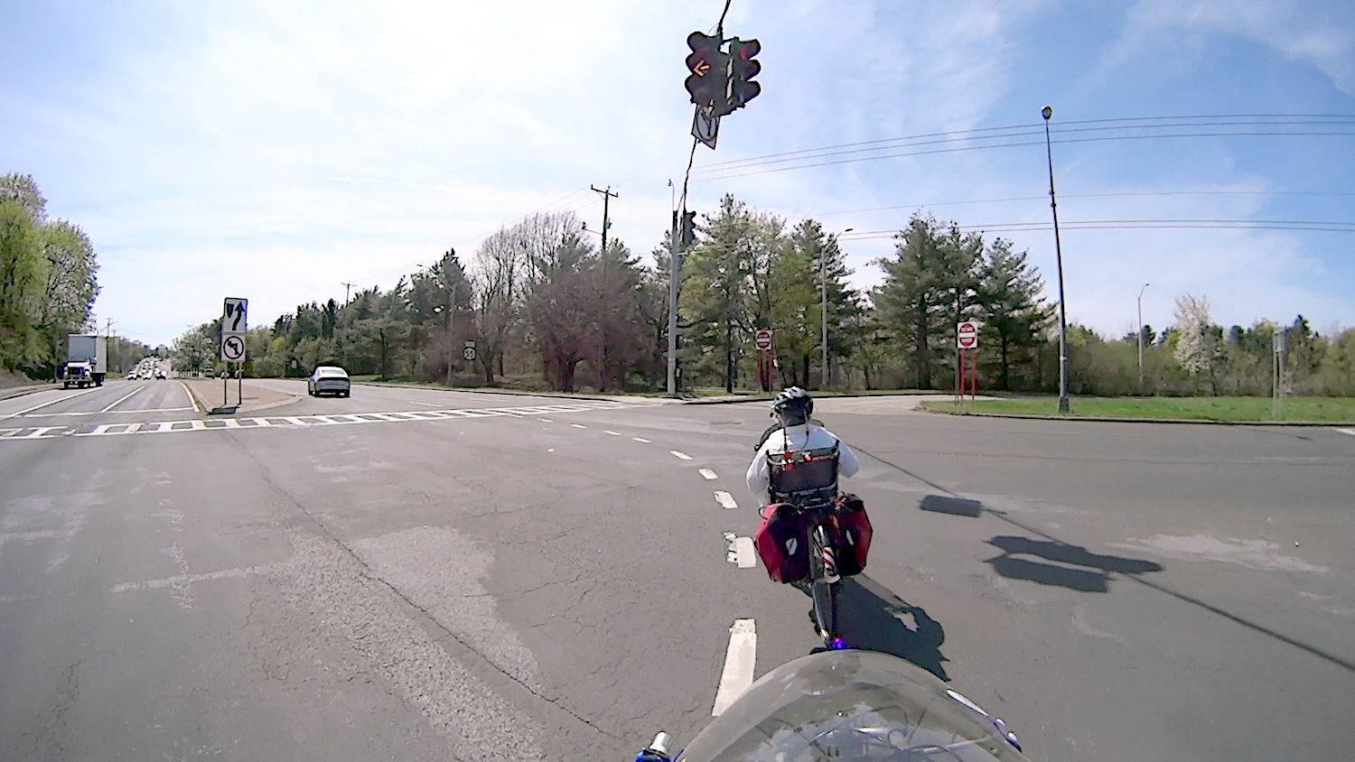
    NYSDOT’s signal timing at Burnett Blvd and Rt 55 remains bicycle-hostile, same as it ever was.

    The OpenSCAD source code and baseplate shape as a GitHub Gist:

    // Sony AS30 helmet mount
    // Ed Nisley – KE4ZNU
    // 2025-04-20
    include <BOSL2/std.scad>
    Layout = "Show"; // [Show,Build,Ball,Tab,Glue]
    Gap = 5; // [0:5:20]
    /* [Hidden] */
    HoleWindage = 0.2;
    Protrusion = 0.1;
    WallThick = 1.0; // enough stiffness against flat pad
    HelmetRadius = 153.0; // from chord equation on curved pad = magic number
    Groove = [30.0,100,3.0,]; // roughly the groove along helmet midline
    Pad = [38,53,10]; // baseplate size, thick enough without fancy trig
    Strap = [3.0,15.0,10*Pad.z]; // hook-n-loop strap holes, double-thick
    Tie = [100,6.0,2.0 + Protrusion]; // cable tie around camera
    TieOffset = 14.0; // … from end of pad
    $fn=96;
    //———-
    // Define shapes
    module Ball() {
    difference() {
    sphere(r=HelmetRadius);
    Tab();
    }
    }
    // Rough approximation of the helmet groove
    module Tab() {
    m = 2.0; // roughly the chord height beyond the tab
    rotate_extrude(convexity=10) {
    right(HelmetRadius)
    zrot(180)
    polygon([
    [0,0],
    [0,Groove.x/2],[Groove.z + m,Groove.x/2],[m,0],
    [Groove.z + m,-Groove.x/2],[0,-Groove.x/2],
    [0,0]
    ],convexity=10);
    }
    }
    // Baseplate with all the cutouts
    module BasePlate() {
    difference() {
    linear_extrude(height=Pad.z,convexity=10)
    import("AS30 Baseplate layout.svg",layer="Baseplate");
    up(WallThick + HelmetRadius)
    yrot(90)
    Ball();
    for (i = [-1,1]) // strap clearance at edge of helmet hole
    right(i*Groove.x/2)
    cube([(Pad.x – Groove.x)/2,Strap.y,Strap.z],center=true);
    for (i = [-1,1]) // cut through edge of pad
    right(i*Pad.x/2)
    cube([(Pad.x – Groove.x),Strap.y,Strap.z],center=true);
    for (j = [-1,1])
    fwd(j*(Pad.y/2 – TieOffset)) up(WallThick)
    cuboid(Tie,anchor=BOTTOM);
    }
    }
    //———-
    // Build things
    if (Layout == "Glue")
    projection(cut=true)
    BasePlate();
    if (Layout == "Tab")
    Tab();
    if (Layout == "Show") {
    xrot(180)
    BasePlate();
    down(WallThick + HelmetRadius + Gap)
    yrot(90)
    color("Orange",0.75) Ball();
    }
    if (Layout == "Build")
    BasePlate();
    if (Layout == "Ball")
    Ball();
    <?xml version="1.0" encoding="UTF-8" standalone="no"?>
    <!– Created with Inkscape (http://www.inkscape.org/) –>
    <svg
    width="11in"
    height="8.5in"
    viewBox="0 0 279.40056 215.90043"
    version="1.1"
    id="SVGRoot"
    inkscape:version="1.4.1 (93de688d07, 2025-03-30)"
    sodipodi:docname="AS30 Baseplate layout.svg"
    xml:space="preserve"
    xmlns:inkscape="http://www.inkscape.org/namespaces/inkscape&quot;
    xmlns:sodipodi="http://sodipodi.sourceforge.net/DTD/sodipodi-0.dtd&quot;
    xmlns:xlink="http://www.w3.org/1999/xlink&quot;
    xmlns="http://www.w3.org/2000/svg&quot;
    xmlns:svg="http://www.w3.org/2000/svg&quot;
    xmlns:rdf="http://www.w3.org/1999/02/22-rdf-syntax-ns#&quot;
    xmlns:cc="http://creativecommons.org/ns#"><sodipodi:namedview
    id="namedview7"
    pagecolor="#ffffff"
    bordercolor="#0000ff"
    borderopacity="1"
    inkscape:pageshadow="0"
    inkscape:pageopacity="0"
    inkscape:pagecheckerboard="1"
    inkscape:document-units="mm"
    showgrid="true"
    units="mm"
    gridtolerance="9.9"
    guidetolerance="10.4"
    inkscape:snap-perpendicular="true"
    inkscape:snap-tangential="true"
    width="700mm"
    borderlayer="false"
    inkscape:showpageshadow="true"
    viewbox-width="700"
    guidecolor="#ff00e3"
    guideopacity="0.49803922"
    inkscape:zoom="1.6945884"
    inkscape:cx="86.451671"
    inkscape:cy="111.82656"
    inkscape:window-width="1780"
    inkscape:window-height="1091"
    inkscape:window-x="0"
    inkscape:window-y="0"
    inkscape:window-maximized="0"
    inkscape:current-layer="layer1"
    objecttolerance="31"
    inkscape:deskcolor="#d1d1d1"
    showguides="true"><inkscape:grid
    type="xygrid"
    id="grid9"
    units="mm"
    spacingx="5"
    spacingy="5"
    dotted="false"
    empspacing="2"
    originx="148.5"
    originy="127.29919"
    color="#ff0000"
    opacity="0.18431373"
    empcolor="#4040ff"
    empopacity="0.49411765"
    visible="true" /><sodipodi:guide
    position="157.7549,120.64599"
    orientation="1,0"
    id="guide1"
    inkscape:locked="false" /></sodipodi:namedview><defs
    id="defs2" /><g
    inkscape:label="Baseplate"
    inkscape:groupmode="layer"
    id="layer1"
    transform="translate(0,5.4354331)"><path
    id="path1"
    style="fill:none;fill-rule:evenodd;stroke:#0c96d9;stroke-width:0.0998686;stroke-linejoin:round"
    d="m -18.99969,190.42075 3.09576,-6.45581 h 32.08112 l 2.82285,6.45581 -10e-6,40.00473 -3.02778,6.53957 -31.33905,-0.14658 -3.63324,-6.39299 z"
    sodipodi:nodetypes="ccccccccc"
    inkscape:label="Aligned path" /></g><g
    inkscape:groupmode="layer"
    id="layer2"
    inkscape:label="Original"><image
    width="57.658115"
    height="65.193459"
    preserveAspectRatio="none"
    xlink:href="AS30%20Baseplate%20scan.jpg"
    id="image1"
    x="112.42073"
    y="67.772316"
    transform="rotate(0.87516737,-355.84202,2.7177945)"
    style="display:inline" /><path
    id="rect1"
    style="fill:none;fill-rule:evenodd;stroke:#0c96d9;stroke-width:0.0998686;stroke-linejoin:round"
    d="m 120.39572,83.160307 3.09576,-6.45581 h 32.08112 l 2.82285,6.45581 -1e-5,40.004733 -3.02778,6.53957 -31.33905,-0.14658 -3.63324,-6.39299 z"
    sodipodi:nodetypes="ccccccccc"
    transform="translate(0,5.4354331)" /></g><metadata
    id="metadata11"><rdf:RDF><cc:Work
    rdf:about=""><cc:license
    rdf:resource="http://creativecommons.org/licenses/by-nc-sa/4.0/&quot; /></cc:Work><cc:License
    rdf:about="http://creativecommons.org/licenses/by-nc-sa/4.0/"><cc:permits
    rdf:resource="http://creativecommons.org/ns#Reproduction&quot; /><cc:permits
    rdf:resource="http://creativecommons.org/ns#Distribution&quot; /><cc:requires
    rdf:resource="http://creativecommons.org/ns#Notice&quot; /><cc:requires
    rdf:resource="http://creativecommons.org/ns#Attribution&quot; /><cc:prohibits
    rdf:resource="http://creativecommons.org/ns#CommercialUse&quot; /><cc:permits
    rdf:resource="http://creativecommons.org/ns#DerivativeWorks&quot; /><cc:requires
    rdf:resource="http://creativecommons.org/ns#ShareAlike&quot; /></cc:License></rdf:RDF></metadata></svg>
    view raw gistfile1.txt hosted with ❤ by GitHub
  • Tour Easy: Broken Seat Parts

    Tour Easy: Broken Seat Parts

    So hardened socket head cap screws survive fifteen years of hard service on my Tour Easy’s seat stay:

    Tour Easy - broken seat stay screw
    Tour Easy – broken seat stay screw

    I replaced both screws with stainless steel 1-½ 10-32 socket head screws, with a reshaped head on the drive side, and we’ll see how long these last.

    A few days later the continuing creak led to finding a broken gear clamp on the left side of the seat back:

    Tour Easy - replacement seat frame clamp
    Tour Easy – replacement seat frame clamp

    Apart from the atypical lack of grime, you couldn’t tell that’s the replacement clamp, because the broken one looked exactly the same way. The clamp strap broke where it bent around the bottom edge of the seat pan bracket, probably due to the flexing caused by the broken seat stay screw.

    Riding season is in full effect!

  • Bird Box: Rotating T-Nuts

    Bird Box: Rotating T-Nuts

    A bird box from long ago emerged from the heap and took its place in an upstairs window:

    Bird Box window mount - installed
    Bird Box window mount – installed

    That big open back held an acrylic sheet letting us watch wrens raise their family; snugging it against the window makes that sheet superfluous. We’re hoping to lure the Wreath Finches from their preferred spot by the front door, but we’re open to any birds in need of a nesting spot.

    The aluminum angle formerly securing the box to various wood window frames wasn’t going to work here, so I conjured a pair of rotating T-nuts to fit the track in the plastic window frame:

    Bird Box window mount - nuts
    Bird Box window mount – nuts

    They’re made from a 5/16-18 T-nut and two layers of 3 mm plywood, all glommed together with E6000-Plus adhesive because it did not scamper out of the way when I opened the Adhesives Cabinet.

    Some doodling convinced me a pair of quarter-circles welded back-to-back, minus cutouts for the metal T-nuts, would suffice:

    Bird Box window mount - nuts
    Bird Box window mount – nuts

    The radius must be a little less than the width of the opening into the channel (20 mm) and the diameter must be a little more than the width of the channel behind that opening (32-ish mm), so I picked 17 mm. The metal T-nut flange is just over 20 mm, but the spike cutouts (omitted from the LightBurn layout) let it slip through the opening.

    A random block of wood positions the box away from the frame enough to clear the outermost flange carrying the screen. Drilling oversize ⅜ inch holes countersunk the top of the T-nut into the block and eliminated excessive alignment fussiness.

    Slicing 20 mm off the bolts fit them into the space available, with a pair of stainless washers covering the gaps.

    A doodle with measurements you won’t need, but surely handy for mounting something else around here:

    Bird Box window mount - size doodles
    Bird Box window mount – size doodles

    Now, to see who takes up residence …

  • Champion Hose Nozzle: Needs a Washer?

    Champion Hose Nozzle: Needs a Washer?

    An email discussion suggested the Champion hose nozzle might, once upon a time, have had a washer between the conical and cylindrical sections.

    So I made one:

    Champion hose nozzle - rubber washer
    Champion hose nozzle – rubber washer

    The details:

    • OD = ½ inch
    • ID = 9/32 inch
    • 2.5 mm stamp pad rubber

    It sealed perfectly, but, just before shutting off, the washer vibrated in the water flow and gave off an ear-shattering (even to my deflicted hearing) howl.

    Perhaps a stiffer and thinner washer with a slightly larger OD would work better.

    A quick check of similar nozzles in the Box o’ Hydraulics shows none of them feel like they have a compliant washer in there, but any sufficiently old rubber will have long since fossilized.

    This seems like a good job for a 3D printed washer with a conical face, made from slightly squishy TPU plastic to ease it past the nozzle’s internal threads. All I need is the ability to print TPU …

  • HQ Sixteen: Handlebar Control Button Labels

    HQ Sixteen: Handlebar Control Button Labels

    The recessed faceplate on the new handlebar control caps for Mary’s HQ Sixteen puts the label flush with the rim:

    Control Button Caps - solid model - show view assembled
    Control Button Caps – solid model – show view assembled

    The current version of the labels isn’t much to look at:

    HQ Sixteen control caps - new caps
    HQ Sixteen control caps – new caps

    The OpenSCAD code produces an SVG outline of the faceplate, surrounded by four alignment targets:

    Control Button Caps - solid model - face view
    Control Button Caps – face view

    Import the SVG into Inkscape and tart it up:

    Control Button Caps - Inkscape
    Control Button Caps – Inkscape

    The alert reader will note the labels are swapped left-for-right.

    The black characters on the left get printed on heavy white paper and laminated; feel free to add artistic embellishments. You must delete the cyan-ish shapes showing the faceplate and switch openings, which just show where the characters will end up, but you must print the four corner targets for alignment.

    The red and orange shapes on the right define the outlines for laser-cutting the laminated paper and adhesive sheet after you import the Inkscape SVG file into LightBurn. The Inkscape colors will automagically put the shapes on separate LightBurn layers, with the cyan-ish shapes going onto non-cutting Tool Layer T2.

    Set the cutting speed & feed to match your machine, lay the laminated labels on the platform, use Print and Cut to align two diagonal corner targets with the corresponding printed targets, then Fire. The. Laser.

    The orange shapes have half a millimeter inset to leave a slight non-sticky margin around the edges:

    HQ Sixteen control caps - adhesive layer
    HQ Sixteen control caps – adhesive layer

    Although those shapes have the same four targets, you align the adhesive by hand and eye. Cut them out, peel one side, stick adhesive to the label, peel the other side, stick adhesive to the faceplate, and you’re done.

    Now, to figure out the switch wiring …

  • HQ Sixteen: Handlebar Control Button Caps

    HQ Sixteen: Handlebar Control Button Caps

    Each of the HQ Sixteen’s handlebars has a cap with control buttons:

    HQ Sixteen control caps - side view
    HQ Sixteen control caps – side view

    The left cap:

    HQ Sixteen control caps - left
    HQ Sixteen control caps – left

    The right cap:

    HQ Sixteen control caps - OEM right
    HQ Sixteen control caps – OEM right

    The membrane switch overlay has textured bumps, although both of us have trouble finding them.

    The Start / Stop switch gets the most use and, as you’d expect, has become intermittent after two decades of use.

    Mary thinks a Start / Stop switch on both caps would be an improvement, letting her position quilting rulers with her right hand and run the machine with her left hand & thumb. I don’t know how the switches are wired, but the wiring suggests either simple single-bit inputs or a small matrix.

    She also finds membrane switches difficult to press, so I’m in the process of replacing the control caps with something more to her liking.

    The current concept goes a little something like this:

    HQ Sixteen control caps - new caps
    HQ Sixteen control caps – new caps

    Stipulated: my art hand is weak.

    Those are little bitty SMD switches:

    HQ Sixteen control caps - new caps overview
    HQ Sixteen control caps – new caps overview

    They’re easy to locate by touch, with a stem length chosen to “feel right” when pushed.

    They have been grievously misapplied:

    HQ Sixteen control caps - switches
    HQ Sixteen control caps – switches

    The solid model has three main pieces and a lock for the ribbon cable:

    Control Button Caps - solid model - build view
    Control Button Caps – solid model – build view

    Those pockets keep the switches oriented while the glue cures.

    Two screws through the handlebar secure each cap. Handi-Quilter drove sheet metal screws into their OEM caps, distorting them enough to jam solidly into the handlebars. I’ve been reluctant to apply enough force to loosen them, so they remain frozen in place until the current quilt is done.

    The new plugs have recesses for M3 square nuts to make them easily removable. As with the handlebar angle adapters, I’ll glue the plugs into the caps.

    A slightly exploded view shows how the pieces fit together:

    Control Button Caps - solid model - show view gapped
    Control Button Caps – solid model – show view gapped

    The switch plate sits recessed into the cap to allow room for the label (about which, more later):

    Control Button Caps - solid model - show view assembled
    Control Button Caps – solid model – show view assembled

    The OpenSCAD source code as a GitHub Gist:

    // Handiquilter HQ Sixteen handlebar control button caps
    // Ed Nisley – KE4ZNU
    // 2025-04-05
    include <BOSL2/std.scad>
    Layout = "Show"; // [Show,Build,Grip,Body,Face,FaceBack,Plug,CableLock]
    // Angle w.r.t. handlebar
    FaceAngle = 30; // [10:45]
    // Separation in Show display
    Gap = 5; // [0:20]
    /* [Hidden] */
    HoleWindage = 0.2;
    Protrusion = 0.1;
    NumSides = 2*3*4;
    WallThick = 3.0;
    ID = 0;
    OD = 1;
    LENGTH = 2;
    Grip = [19.7,22.4,15.0]; // (7/8)*INCH = 22.2 mm + roughness, LENGTH=OEM insertion depth
    GripRadius = Grip[OD]/2;
    FoamOD = 34.0; // handlebar foam
    FoamRadius = FoamOD/2;
    SwitchBody = [6.3,6.3,4.0]; // does not include SMD leads
    SwitchStemOD = 3.5 + 2*HoleWindage;
    SwitchOC = 10.0; // center-to-center switch spacing
    LabelThick = 0.5; // laminated overlay
    FaceRim = 2.0; // rim around faceplate
    FaceThick = 2.0; // … plate thickness
    FaceDepth = FaceThick + LabelThick; // inset allowing for faceplate label
    CapOD = 38.0; // overall cap diameter
    CapTrim = FoamRadius; // flat trim on front
    CapBase = 5.0; // bottom thickness
    Cap = [FoamOD – FaceRim,CapOD,CapBase + CapOD*tan(FaceAngle)];
    echo(Cap=Cap);
    TargetSize = 4.0; // laser alignment targets
    TargetsOC = [40.0,40.0];
    Cable = [10.0,2.0,WallThick]; // aperture for cable lock
    ScrewAngles = [-45,45]; // mounting screws
    Screw = [2.0,3.0,7.0]; // OEM = sheet metal screw
    ScrewOffset = 6.0; // from top of grip tube
    SquareNut = [3.0,5.5,2.3 + 0.4]; // M3 square nut OD = side, LENGTH + inset allowance
    NutInset = GripRadius – sqrt(pow(GripRadius,2) – pow(SquareNut[OD],2)/4);
    PlugOA = [(Grip[ID] – 2*WallThick),(Grip[ID] – 1.0),(CapBase + ScrewOffset + 10.0)];
    echo(PlugOA=PlugOA);
    //———-
    // Define objects
    //—–
    // Handlebar tube
    module GripTube() {
    difference() {
    tube(3*Grip[LENGTH],GripRadius,Grip[ID]/2,anchor=TOP);
    for (a = ScrewAngles) {
    down(ScrewOffset) zrot(a-90)
    right(GripRadius)
    yrot(90) cylinder(d=Screw[OD],h=Screw[LENGTH],center=true,$fn=6);
    }
    }
    }
    //—–
    // SVG outline of faceplate for laser cuttery
    module FaceShape(Holes=true,Targets=false) {
    difference() {
    scale([1,1/cos(FaceAngle)])
    difference() {
    circle(d=(Cap[OD] – 2*FaceRim),$fn=144);
    fwd(CapTrim – FaceRim)
    square(Cap[OD],anchor=BACK);
    }
    if (Holes)
    for (i=[-1:1]) // arrange switch stem holes
    right(i*SwitchOC)
    zrot(180/8) circle(d=SwitchStemOD,$fn=32);
    }
    if (Targets)
    for (i = [-1,1], j = [-1,1])
    translate([i*TargetsOC.x/2,j*TargetsOC.y/2])
    square(2.0,center=true);
    }
    //—–
    // Faceplate backing sheet
    // Switch bodies indented into bottom, so flip to build
    module FacePlate(Thick=FaceThick,Holes=true) {
    difference() {
    linear_extrude(height=Thick,convexity=5)
    FaceShape(Holes);
    up(SwitchBody.z/4)
    for (i = [-1:1])
    right(i*SwitchOC)
    cube(SwitchBody,anchor=TOP);
    }
    }
    //—–
    // Cap body
    module CapBody() {
    $fn=48;
    up(CapBase + (Cap[OD]/2)*tan(FaceAngle)) xrot(FaceAngle)
    difference() {
    xrot(-FaceAngle)
    down(CapBase + (Cap[OD]/2)*tan(FaceAngle))
    difference() {
    cylinder(d=Cap[OD],h=Cap[LENGTH]);
    fwd(CapTrim) down(Protrusion)
    cube(2*Cap[LENGTH],anchor=BACK+BOTTOM);
    up(CapBase)
    difference() {
    cylinder(d=Cap[ID],h=Cap[LENGTH]);
    fwd(CapTrim – 2*FaceRim)
    cube(2*Cap[LENGTH],anchor=BACK+BOTTOM);
    }
    down(Protrusion)
    cylinder(d=Grip[ID],h=Cap[LENGTH]);
    }
    cube(2*Cap[OD],anchor=BOTTOM);
    down(FaceDepth)
    FacePlate(FaceDepth + Protrusion,Holes=false);
    }
    }
    //—–
    // Plug going into grip handlebar
    module CapPlug() {
    $fn=48;
    difference() {
    tube(PlugOA[LENGTH],id=PlugOA[ID],od=PlugOA[OD],anchor=BOTTOM)
    position(TOP)
    tube(CapBase,id=PlugOA[ID],od=Grip[ID],anchor=TOP);
    for (a = ScrewAngles)
    up(PlugOA.z – CapBase – ScrewOffset) zrot(a-90)
    right(PlugOA[ID]/2)
    yrot(90) {
    cube([SquareNut[OD],SquareNut[OD],SquareNut[LENGTH] + NutInset],center=true);
    zrot(180/6)
    cylinder(d=(SquareNut[ID] + 2*HoleWindage),h=PlugOA[ID],center=true,$fn=6);
    }
    }
    }
    //—–
    // Lock plate for ribbon cable
    module CableLock() {
    difference() {
    cuboid([2*Cable.x,PlugOA[ID],WallThick],rounding=WallThick/2,anchor=BOTTOM);
    for (j = [-1,1])
    back(j*Cable.y) down(Protrusion)
    cube(Cable + [0,0,2*Protrusion],anchor=BOTTOM);
    }
    }
    //———-
    // Build things
    if (Layout == "Grip") {
    color("Silver",0.5)
    GripTube();
    }
    if (Layout == "Face")
    FaceShape(Targets=true);
    if (Layout == "FaceBack")
    FacePlate();
    if (Layout == "Body")
    CapBody();
    if (Layout == "Plug")
    CapPlug();
    if (Layout == "CableLock")
    CableLock();
    if (Layout == "Show") {
    color("Green")
    up(CapBase)
    CableLock();
    color("Orange")
    down(Gap)
    down(PlugOA[LENGTH] – CapBase)
    CapPlug();
    color("Cyan",(Gap > 4)? 1.0 : 0.2)
    CapBody();
    color("White",(Gap > 4)? 1.0 : 0.5)
    up(Gap*cos(FaceAngle)) fwd(Gap*sin(FaceAngle))
    up(CapBase + (Cap[OD]/2)*tan(FaceAngle) – FaceDepth)
    back(FaceDepth*sin(FaceAngle)) xrot(FaceAngle)
    FacePlate();
    down(3*Gap) {
    color("Silver",0.5)
    GripTube();
    down(Gap)
    color("Gray",0.5)
    tube(3*Grip[LENGTH],FoamRadius,Grip[OD]/2,anchor=TOP);
    }
    }
    if (Layout == "Build") {
    right((Gap + Cap[OD])/2)
    CapBody();
    left((Gap + Cap[OD])/2)
    zrot(180) up(FaceThick) xrot(180)
    FacePlate();
    fwd(Gap + Cap[OD])
    up(PlugOA[LENGTH]) xrot(180) zrot(180)
    CapPlug();
    fwd(Cap[OD]/2)
    zrot(90)
    CableLock();
    }

  • HQ Sixteen: Bobbin Winder Split Shaft Tweak

    HQ Sixteen: Bobbin Winder Split Shaft Tweak

    The HQ Sixteen has much larger bobbins than Mary’s Kenmore and Juki sewing machines. It also came with a dedicated bobbin winder:

    HQ Sixteen bobbin winder - overview
    HQ Sixteen bobbin winder – overview

    That thing has a distinct Industrial Revolution aspect compared to the BarbieCore bobbin winder I laid hands on a while ago.

    Out of the photo on the right:

    • The thread cone and guide tower
    • The thread tension disks

    Mary had been having trouble winding the bobbins, as the tension seemed entirely too low and the thread did not lay smoothly across the bobbin, so she asked me to take a look.

    The motor shaft has an O-ring for friction drive against the large wheel driving the shaft with the bobbin on the other end. The small silver lever over on the left flips an over-center lock pressing the wheel against the O-ring and tripping the microswitch in the aluminum housing, thus turning the motor on. The bobbin fills until a small finger monitoring the thread level flips the lock back over center, the wheel disengages, the switch turns the motor off, and a spring drives the wheel against the rubber rod in the upper left.

    Which worked well, but all the bobbins had a loose-to-sloppy fit on the shaft, to the extent that the shaft really couldn’t drive them against any thread tension.

    Loosening the screw holding the drive wheel on the shaft lets it slip off and the shaft slides out to the front:

    HQ Sixteen bobbin winder - split shaft
    HQ Sixteen bobbin winder – split shaft

    The sides of the split shaft should press firmly against the bobbin core, but that just wasn’t happening.

    Measuring a dozen bobbins showed most had an ID of 6.04 mm, with a few around 6.01 mm; unsurprisingly, the latter had the best, albeit still loose, fit. Conversely, the split shaft had two isolated points 6.01 mm apart across a diameter, with the remainder around 5.95 mm. Those are not large differences, but it was obvious why the bobbins didn’t wind correctly.

    I filed some graunch off the split edges, then gently pushed the Designated Prydriver into the end of the split to spread the sides juuuust a little bit, until all the bobbins pushed on firmly and fit snugly:

    HQ Sixteen bobbin winder - split shaft test fit
    HQ Sixteen bobbin winder – split shaft test fit

    It reassembled in reverse order and we’ll see how it behaves during the next marathon bobbin-filling session.