The Smell of Molten Projects in the Morning

Ed Nisley's Blog: Shop notes, electronics, firmware, machinery, 3D printing, laser cuttery, and curiosities. Contents: 100% human thinking, 0% AI slop.

Category: Machine Shop

Mechanical widgetry

  • TCRT5000 Proximity Sensor Mount

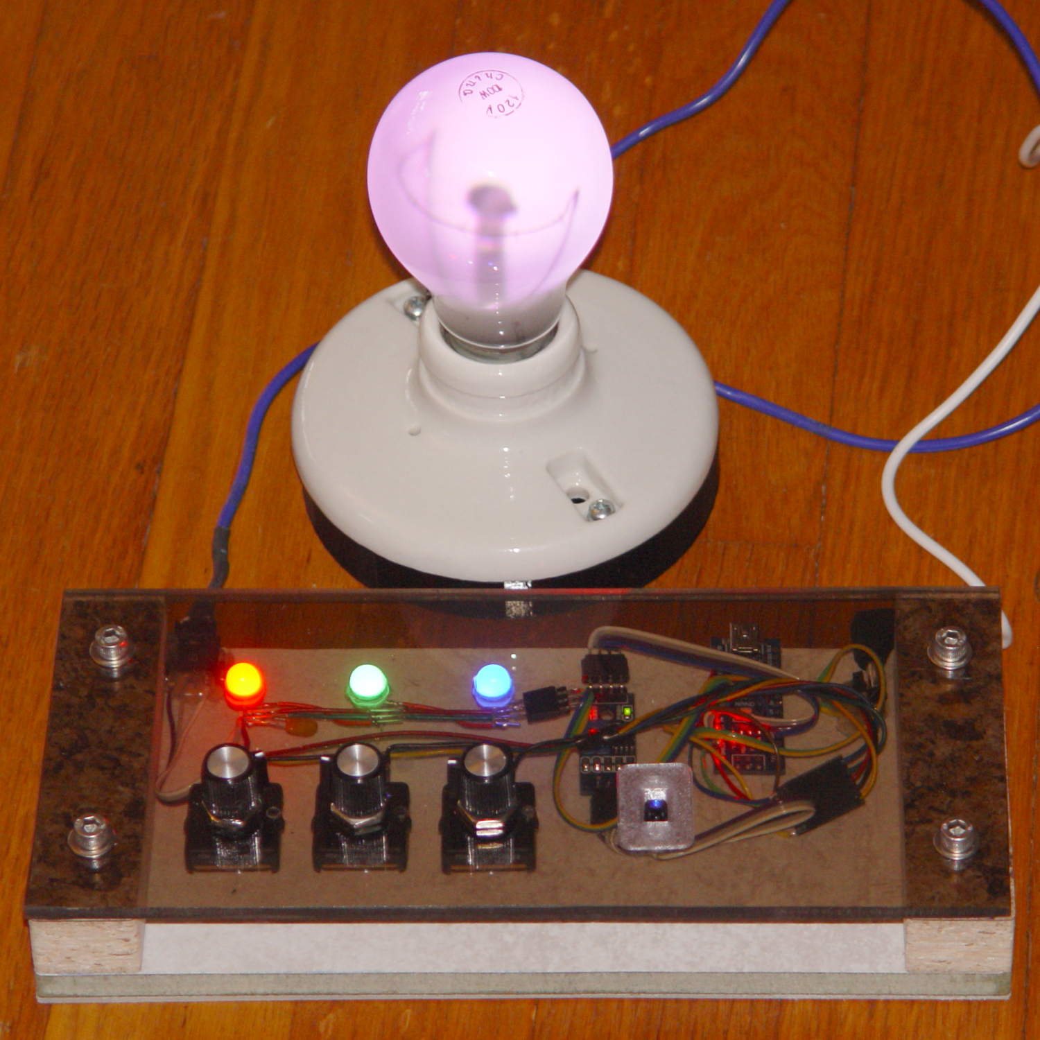
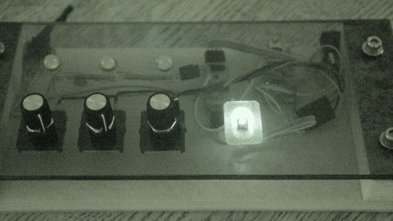
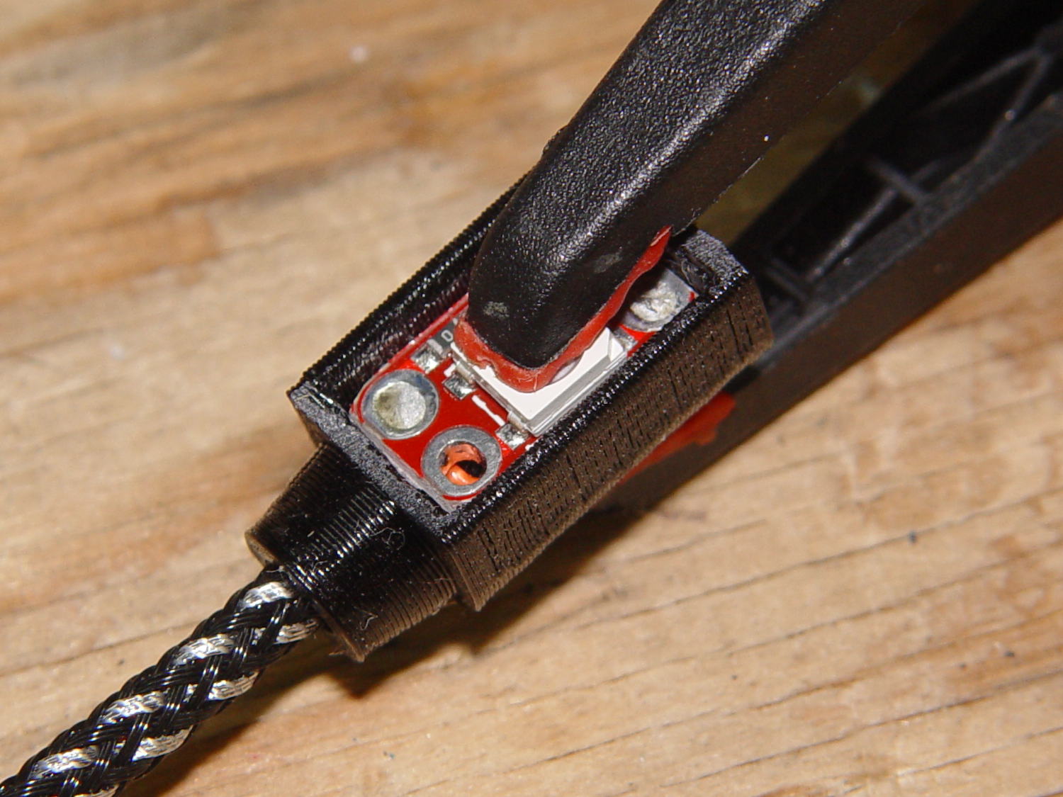
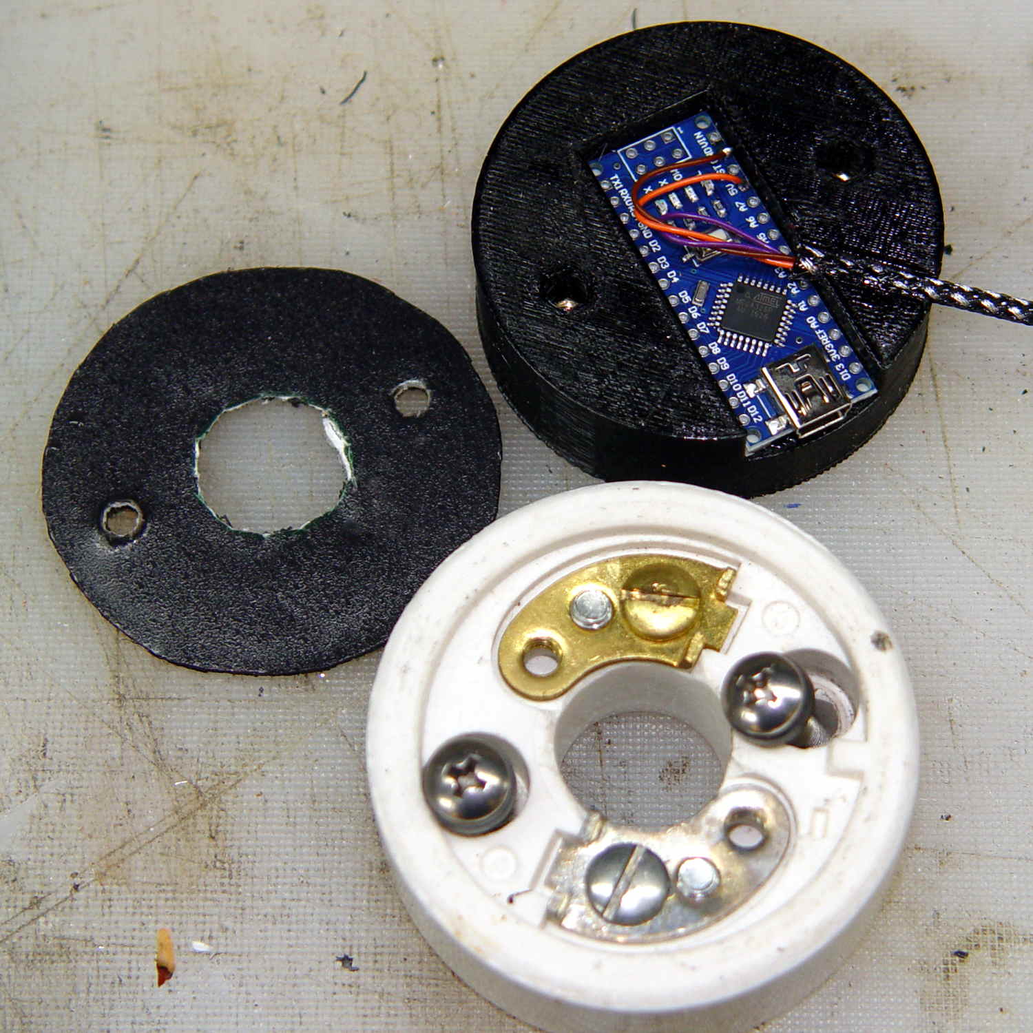
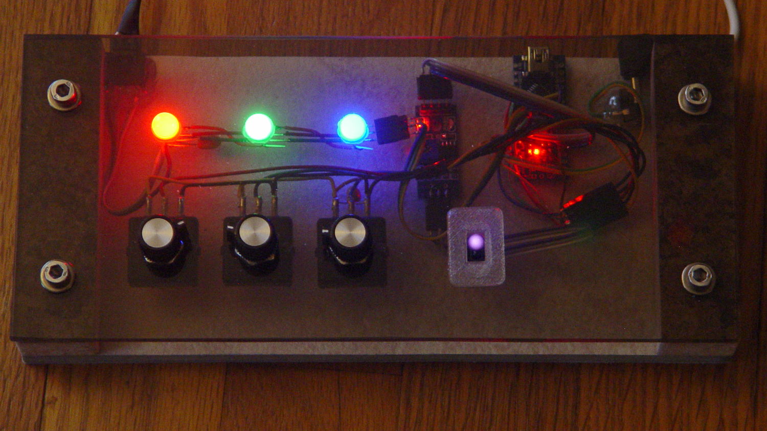
    Having a few TCRT5000 proximity sensors lying around, I used one for the Color Mixer so folks could just wave a finger to flip the LED colors, rather than pound relentlessly on the top plate:

    Color mixer - controls
    Color mixer – controls

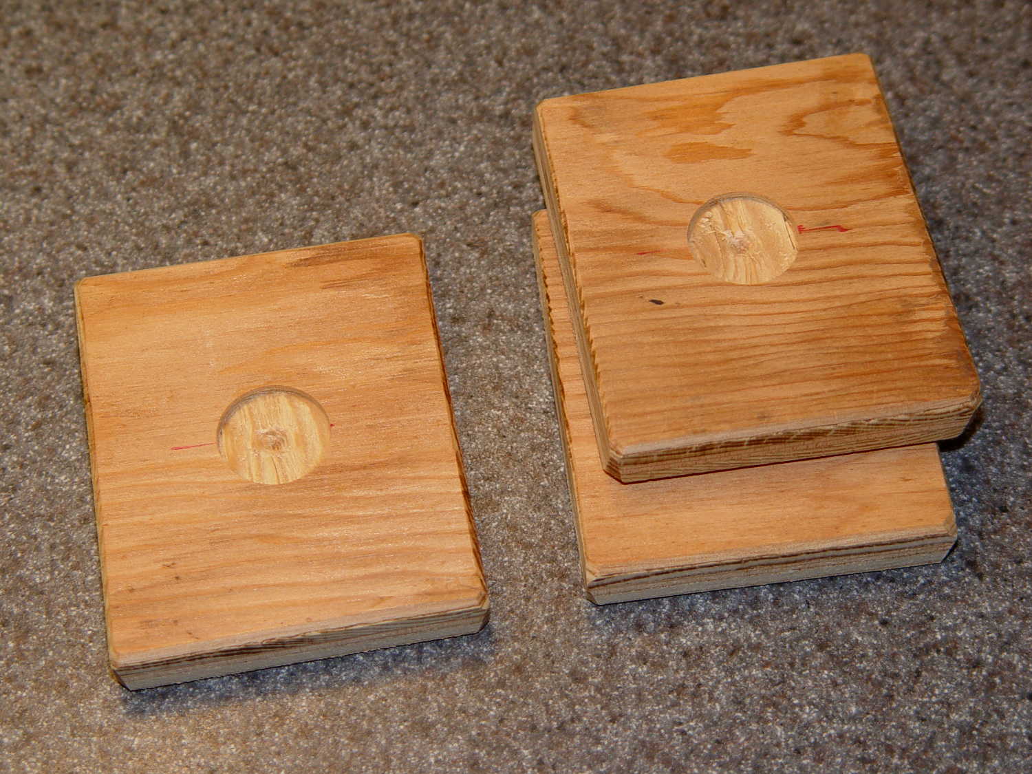
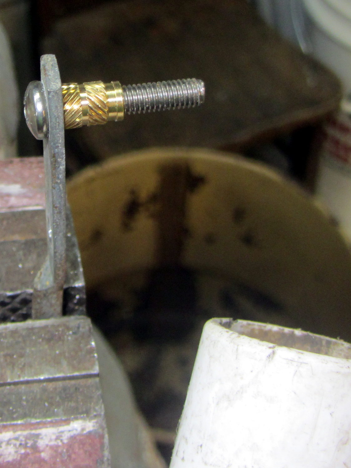
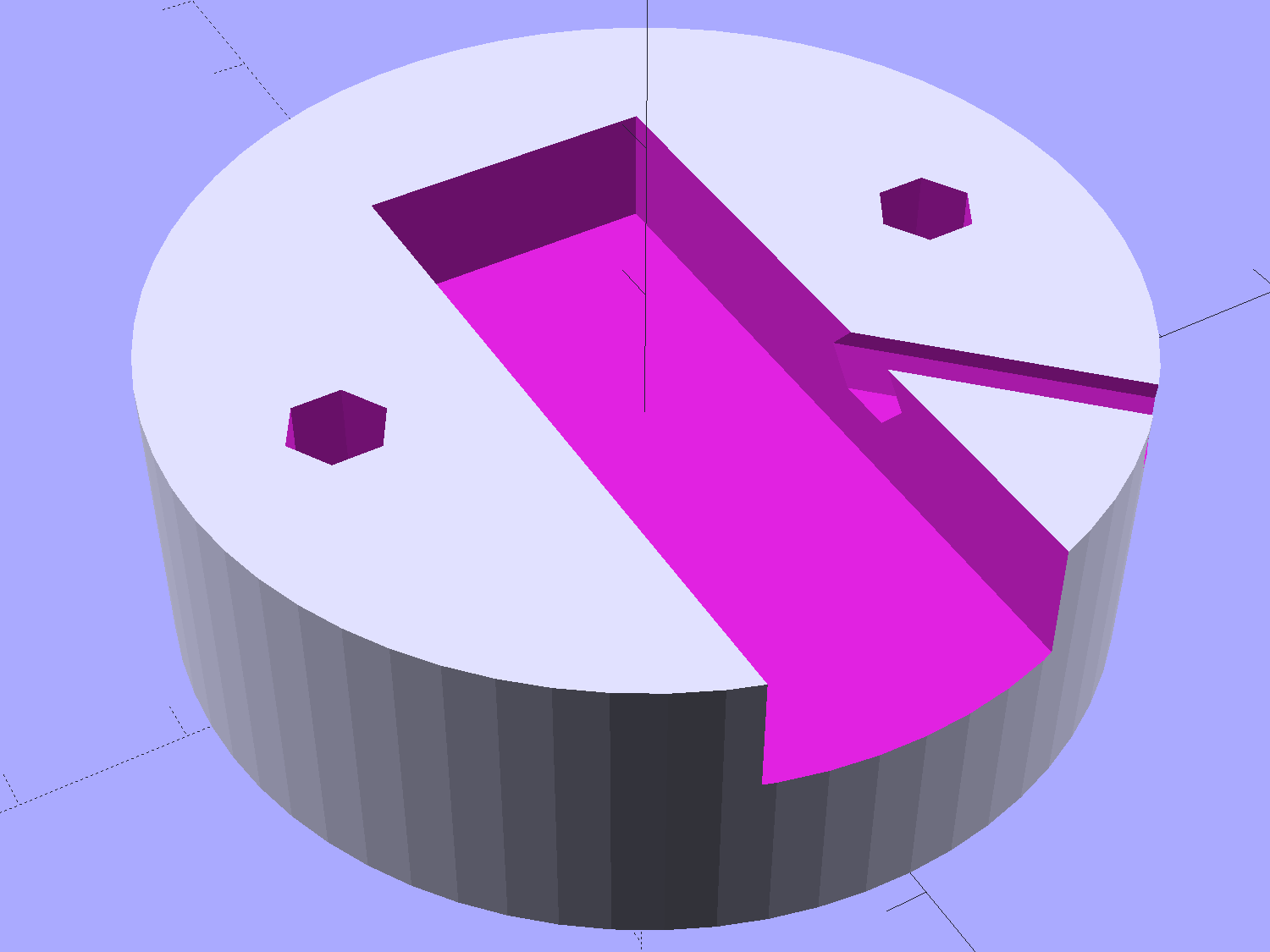
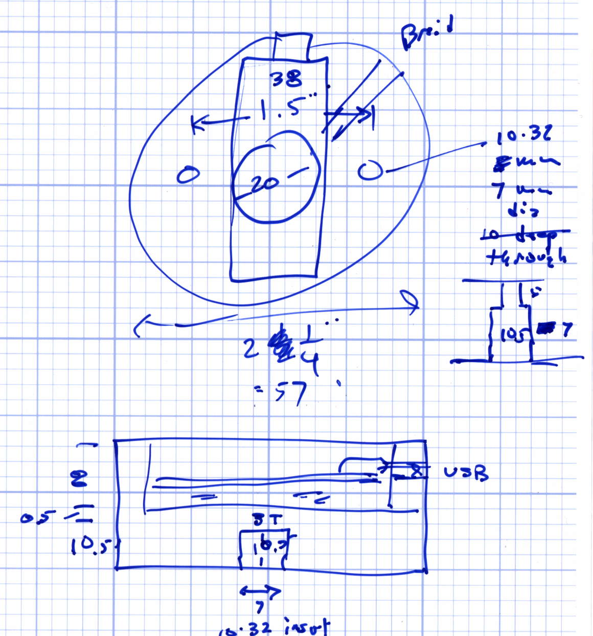
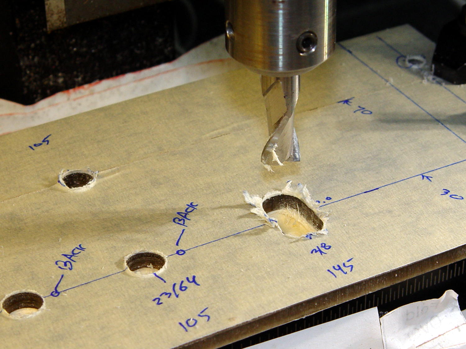
    The stem fits into a slot made with a 3/8 inch end mill:

    Prox Sensor Bezel - Slic3r preview
    Prox Sensor Bezel – Slic3r preview

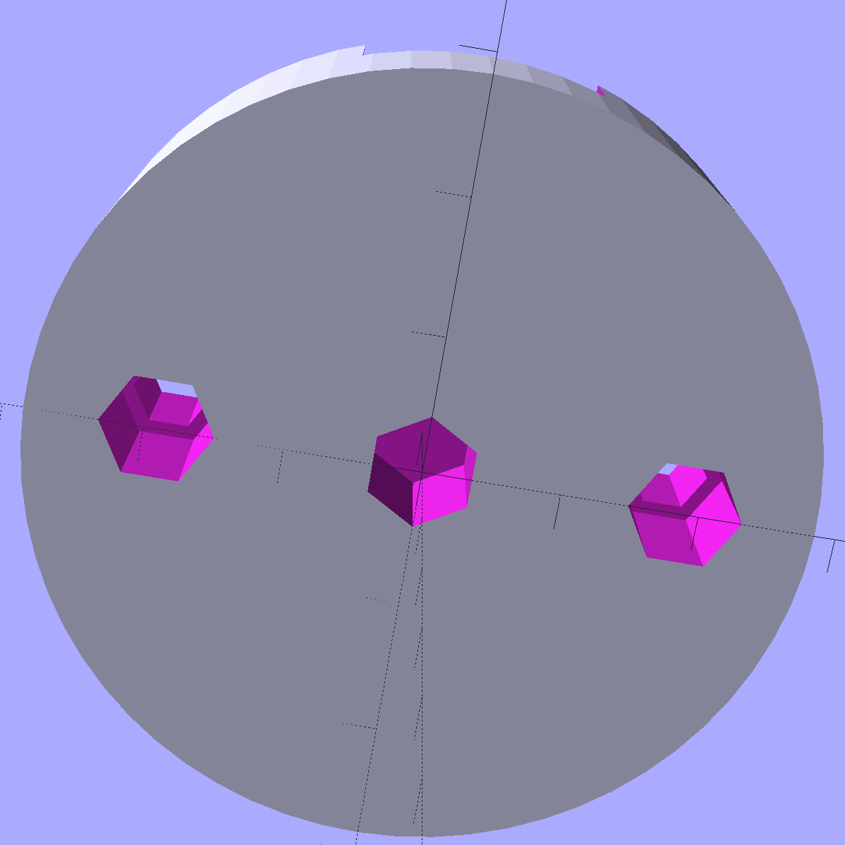
    You move the cutter by the length of the sensor (10.0 mm will work) to make the slot. In practical terms, drill a hole at the midpoint, insert the cutter, then move ±5.0 mm from the center:

    Prox sensor panel cut
    Prox sensor panel cut

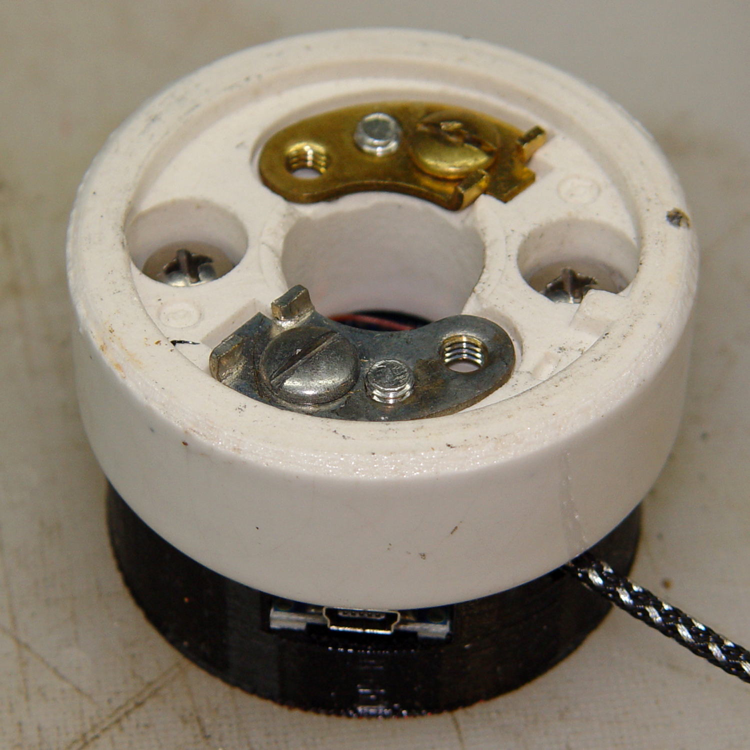
    A bead of epoxy around the stem on the bottom of the panel should hold it in place forevermore.

    The rectangular inner hole came out a tight push fit for the TCRT5000 sensor, so I didn’t bother gluing it in place and, surprisingly, it survived the day unscathed!

    The OpenSCAD source code as a GitHub Gist:

    // TCRT5000 Proximity switch sensor mount
    // Ed Nisley KE4ZNU – October 2016
    Layout = "Build"; // Show Build
    //- Extrusion parameters must match reality!
    ThreadThick = 0.25;
    ThreadWidth = 0.40;
    HoleWindage = 0.2;
    Protrusion = 0.1; // make holes end cleanly
    inch = 25.4;
    function IntegerMultiple(Size,Unit) = Unit * ceil(Size / Unit);
    //———————-
    // Dimensions
    Sensor = [5.9,10.0,7.0];
    SensorHoleCutter = 3/8 * inch;
    echo(str("Cutter dia: ",SensorHoleCutter," mm"));
    echo(str("Cutter motion: ",Sensor[1]," mm"));
    PanelThick = 5.0;
    StemLength = PanelThick + 6*ThreadThick;
    FlangeThick = 3 * ThreadThick;
    //———————-
    // Flange model
    module ProxFlange() {
    difference() {
    union() {
    linear_extrude(height=FlangeThick)
    hull()
    for (i=[-1,1], j=[-1,1])
    translate([i*Sensor[0],j*Sensor[1]])
    circle(r=Sensor[0]/2,$fn=8*4);
    translate([0,0,-StemLength])
    linear_extrude(height=StemLength)
    hull()
    for (j=[-1,1])
    translate([0,j*Sensor[1]/2])
    circle(d=SensorHoleCutter,$fn=8*4);
    }
    translate([0,0,-Protrusion])
    cube(Sensor + [HoleWindage,HoleWindage,2*(PanelThick + Protrusion)],center=true);
    }
    }
    //———————-
    // Build it
    if (Layout == "Show")
    ProxFlange();
    if (Layout == "Build")
    translate([0,0,FlangeThick])
    rotate([180,0,0])
    ProxFlange();
  • Vacuum Tube Lights: Poughkeepsie Day School Mini Maker Faire 2016

    Should you be around Poughkeepsie today, drop in on the Poughkeepsie Day School’s Mini Maker Faire, where I’ll be showing off some glowy LED goodness:

    21HB5A on platter - orange green
    21HB5A on platter – orange green

    The 5U4GB side lighted dual rectifier looks pretty good after I increased the phase between the two LEDs:

    5U4GB Full-wave vacuum rectifier - cyan red phase
    5U4GB Full-wave vacuum rectifier – cyan red phase

    A gaggle of glowing vacuum tubes makes for a rather static display, though, so I conjured a color mixer so folks could play with the colors:

    Color mixer - overview
    Color mixer – overview

    Three analog potentiometers set the intensity of the pure RGB colors on the 8 mm Genuine Adafruit Neopixels. A closer look at the circuitry shows it’s assembled following a freehand “the bigger the blob, the better the job” soldering technique:

    Color mixer - controls
    Color mixer – controls

    The blended RGB color from a fourth Neopixel backlights the bulb to project a shadow of the filament on the front surface:

    Color mixer - bulb detail
    Color mixer – bulb detail

    It’s worth noting that the three Genuine Adafruit 8 mm Neopixels have a nonstandard RGB color layout, while the knockoff 5050 SMD Neopixel on the bulb has the usual GRB layout. You can’t mix-n-match layouts in a single Neopixel string, so a few lines of hackage rearrange the R and G values to make the mixed colors come out right.

    An IR proximity sensor lets you invert the colors with the wave of a fingertip to send Morse code in response to (some of) the vacuum tubes on display nearby. The sensor glows brightly in pure IR, with all the other LEDs going dark:

    Color mixer - controls - IR image
    Color mixer – controls – IR image

    The switch sits in a little printed bezel to make it big enough to see. The slight purple glow in the visible-light picture comes from the camera’s IR sensitivity; you can’t see anything with your (well, my) unaided eyes.

    The “chassis” emerged from the wood pile: a slab of laminate flooring and two strips of countertop, with a slab of bronze-tint acrylic from a Genuine IBM PC Printer Stand that had fallen on hard times quite a while ago. Bandsaw to size, belt-sand to smooth; nothing particularly precise, although I did use the Sherline for coordinate drilling:

    Color mixer panel - drill setup
    Color mixer panel – drill setup

    That’s laying it all out by hand to get a feel for what it’ll look like and drilling the holes at actual coordinates to make everything line up neatly.

    Hot melt glue and epoxy hold everything together, with foam tape securing the two PCBs. Those cap screws go into 10-32 brass inserts hammered into the laminate flooring strip.

    There’s no schematic. Connect the pots to A0 through A2, wire the Neopixels in series from D8 with the bulb LED last in the string, wire the prox sensor to D9, and away you go.

    It’s fun to play with colors!

    The Arduino source code as a GitHub Gist:

    // Color mixing demo for Mini Maker Faire
    // Ed Nisley – KE4ANU – November 2016
    #include <Adafruit_NeoPixel.h>
    //———-
    // Pin assignments
    #define PIN_NEO 8 // DO – data out to first Neopixel
    #define PIN_HEARTBEAT 13 // DO – Arduino LED
    #define PIN_FLASH 9 // DI – flash button
    #define PIN_POTRED A0 // AI – red potentiometer
    #define PIN_POTGREEN A1 // AI – green potentiometer
    #define PIN_POTBLUE A2 // AI – blue potentiometer
    //———-
    // Constants
    #define PIXELS 4 // number of pixels
    #define PIXEL_RED 2 // physical channel layout
    #define PIXEL_GREEN 1
    #define PIXEL_BLUE 0
    #define PIXEL_MIX (PIXELS – 1) // pixel with mixed color
    #define PIXEL_FLASH (PIXELS – 1) // pixel that flashes
    // update LEDs only this many ms apart (minus loop() overhead)
    #define UPDATEINTERVAL 25ul
    #define UPDATEMS (UPDATEINTERVAL – 1ul)
    //———-
    // Globals
    // instantiate the Neopixel buffer array
    // color order is RGB for 8 mm diffuse LEDs, GRB for mixed 5050 LED at end
    Adafruit_NeoPixel strip = Adafruit_NeoPixel(PIXELS, PIN_NEO, NEO_RGB + NEO_KHZ800);
    uint32_t FullWhite = strip.Color(255,255,255);
    uint32_t FullOff = strip.Color(0,0,0);
    // colors in each LED
    enum pixcolors {RED, GREEN, BLUE, PIXELSIZE};
    uint32_t PotColors[PIXELSIZE];
    uint32_t UniColor;
    unsigned long MillisNow;
    unsigned long MillisThen;
    //– Helper routine for printf()
    int s_putc(char c, FILE *t) {
    Serial.write(c);
    }
    //——————
    // Set the mood
    void setup() {
    pinMode(PIN_HEARTBEAT,OUTPUT);
    digitalWrite(PIN_HEARTBEAT,LOW); // show we arrived
    Serial.begin(57600);
    fdevopen(&s_putc,0); // set up serial output for printf()
    printf("Color Mixer Demo for Mini Maker Faire\r\nEd Nisley – KE4ZNU – November 2016\r\n");
    // set up pixels
    strip.begin();
    strip.show();
    // lamp test: a brilliant white flash on all pixels
    // pixel color layout doesn't matter for a white flash
    printf("Lamp test: flash white\r\n");
    for (byte i=0; i<5 ; i++) {
    for (int j=0; j < strip.numPixels(); j++) { // fill LEDs with white
    strip.setPixelColor(j,FullWhite);
    }
    strip.show();
    delay(500);
    for (int j=0; j < strip.numPixels(); j++) { // fill LEDs with black
    strip.setPixelColor(j,FullOff);
    }
    strip.show();
    delay(500);
    }
    // lamp test: walk a white flash along the string
    printf("Lamp test: walking white\r\n");
    strip.setPixelColor(0,FullWhite);
    strip.show();
    delay(500);
    for (int i=1; i<strip.numPixels(); i++) {
    digitalWrite(PIN_HEARTBEAT,HIGH);
    strip.setPixelColor(i-1,FullOff);
    strip.setPixelColor(i,FullWhite);
    strip.show();
    digitalWrite(PIN_HEARTBEAT,LOW);
    delay(500);
    }
    strip.setPixelColor(strip.numPixels() – 1,FullOff);
    strip.show();
    delay(500);
    MillisNow = MillisThen = millis();
    }
    //——————
    // Run the mood
    void loop() {
    MillisNow = millis();
    if ((MillisNow – MillisThen) >= UPDATEMS) { // time for color change?
    digitalWrite(PIN_HEARTBEAT,HIGH);
    PotColors[RED] = strip.Color(analogRead(PIN_POTRED) >> 2,0,0);
    PotColors[GREEN] = strip.Color(0,analogRead(PIN_POTGREEN) >> 2,0);
    PotColors[BLUE] = strip.Color(0,0,analogRead(PIN_POTBLUE) >> 2);
    strip.setPixelColor(PIXEL_RED,PotColors[RED]); // load up pot indicators
    strip.setPixelColor(PIXEL_GREEN,PotColors[GREEN]);
    strip.setPixelColor(PIXEL_BLUE,PotColors[BLUE]);
    strip.setPixelColor(PIXEL_MIX,strip.getPixelColor(PIXEL_RED) |
    strip.getPixelColor(PIXEL_GREEN) |
    strip.getPixelColor(PIXEL_BLUE));
    if (PIXEL_FLASH != PIXEL_MIX) {
    strip.setPixelColor(PIXEL_FLASH,strip.getPixelColor(PIXEL_MIX));
    }
    if (LOW == digitalRead(PIN_FLASH)) { // if flash input active, overlay flash
    strip.setPixelColor(PIXEL_FLASH,0x00FFFFFF ^ strip.getPixelColor(PIXEL_FLASH));
    strip.setPixelColor(PIXEL_RED, 0x00FF0000 ^ strip.getPixelColor(PIXEL_RED));
    strip.setPixelColor(PIXEL_GREEN,0x0000FF00 ^ strip.getPixelColor(PIXEL_GREEN));
    strip.setPixelColor(PIXEL_BLUE, 0x000000FF ^ strip.getPixelColor(PIXEL_BLUE));
    }
    UniColor = 0x000000ff & strip.getPixelColor(PIXELS – 1); // hack to rearrange colors for 5050 LED
    UniColor |= 0x00ff0000 & (strip.getPixelColor(PIXELS – 1) << 8);
    UniColor |= 0x0000ff00 & (strip.getPixelColor(PIXELS – 1) >> 8);
    strip.setPixelColor(PIXELS – 1,UniColor);
    strip.show(); // send out colors
    MillisThen = MillisNow;
    digitalWrite(PIN_HEARTBEAT,LOW);
    }
    }
    view raw ColorMixer.ino hosted with ❤ by GitHub
  • Vacuum Tube LEDs: Mogul Socket With Platters

    Adding two hard drive platters draws attention away from the printed puck holding the microcontroller:

    500 W Incandescent - Mogul socket with platters
    500 W Incandescent – Mogul socket with platters

    Granted, it looks odd. I think it’s a step in the right direction, if there is any right direction at all.

  • More Kickstand Plates

    Having recently left the last of the kickstand plates somewhere along our route, I bandsawed, belt-sanded, and Forstner-drilled a new set:

    Kickstand plates
    Kickstand plates

    The slightly rectangular shape extracted four plates from of a scrap of 3/8 inch plywood, with almost nothing left over. The fourth plate had already found its way into the under-seat bag by the time I thought of a picture.

    My can of fluorescent red paint having lost its mojo since the most recent application, these shall remain unpainted forever more; as even forget-me-not red seems to have little effect, that may not matter.

  • Cast Iron Pan Seasoning: Low-woo Results

    The original cast-iron seasoning recipe, after half a dozen iterations of flax seed oil & high-temperature baking, produced disappointing results:

    Wagner cast iron skillet - washed - top
    Wagner cast iron skillet – washed – top

    The key point of seasoning seems to require heating the oil enough to polymerize its molecular thingies, with (IMO) pretty nearly everything else boiling down to woo.

    Since that rusting incident, I’ve done this after every use:

    • Wipe the pan clean with the same hot soapy water I use for everything else
    • Remove crud with the same Scotchbrite / sponge pad I use for everything else
    • Rinse and wipe dry with the sponge side of the pad
    • Set stove timer for 3 minutes
    • Put pan on simmer burner, set to high flame
    • Continue cleanup until timer sounds
    • Set stove timer for 3 minutes
    • Wipe half a dozen drops of flax seed oil around pan with cotton cloth scrap
    • Continue cleanup until timer sounds
    • Turn off simmer burner
    • Wipe pan with that oily cotton scrap

    The pan reaches about 300 °F after 3 minutes. The “opening the pores” thing is woo, but a completely dry pan doesn’t spit back and that’s a major plus.

    The pan tops out at a bit over 400 °F after a total of 6 minutes. There’s no smoke, no excitement, just a hot pan on the back burner.

    Given that I’m washing the pan anyway, the whole “seasoning” operation adds maybe two minutes to the process. By now, it’s entirely automatic.

    Nota Bene: Set the timer before turning on the burner and before adding the oil, because you will become distracted and will not remember the pan quietly heating on the back burner. You have been warned.

    After two months of doing that about once a day:

    Wagner Cast Iron Skillet - Low Woo Seasoning
    Wagner Cast Iron Skillet – Low Woo Seasoning

    Granted, it looks about the same as the previous results, but this uniform dull black coating repels water, doesn’t rust, loves oil, wipes clean without scouring, and the daily omelet doesn’t stick hardly at all. Obviously, the key difference is that I’ve polymerized a gazillion coats of oil, rather than half a dozen.

    Although I have no idea whether I’m exposing us to lethal free radicals created by the polymerization process, I doubt anybody else knows anything on that subject with regard to their own seasoning technique, so we’re pretty much even. As with most such worries, It Doesn’t Matter.

    Next, I’ll just wipe the pan and let it dry in the rack. That coating should eventually wear off, at least in the high-traffic areas; let’s see how little maintenance it requires.


  • Storm Door Brace: Now, With Inserts!

    The mid-1950s wood doors on our house have wood storm doors with interchangeable wood-framed glass and screen panels. Twice a year, the diligent homeowner will swap the panels to match the season; during the last 60+ years, the glass panels remain undropped.

    The back door has a diagonal tension brace to hold the door in shape; the door may be slightly distorted or the frame slightly out of square. In any event, the brace obstructs the panel, so the semiannual ritual includes loosening the brace and removing four screws. During the last 60+ years, the screw holes have required repair / filling several times; about five years ago, I plugged them with epoxy putty and drilled them to fit the screws.

    That repair having aged out, I was about to renew the epoxy when I realized that I now have brass inserts that would work even better, if I replaced the original wood screws with 10-32 machine screws.

    I cut the screws to the exact length using the brace and brass insert as a fixture:

    Storm door - screw cutting
    Storm door – screw cutting

    The vacuum cleaner nozzle to the lower right inhales the debris from the Dremel cutoff wheel that would otherwise fill the shop; I used up the last half of a wheel on four stainless steel screws.

    Because each end of the brace has two screws, I knew that I couldn’t just drill out the four holes, plant four inserts, and be done with the job: the first insert on each end could go pretty nearly anywhere, but the second insert must match the brace hole spacing. The only way I know how to do that is to epoxy the first two inserts in place and let them cure, drill the other two holes slightly oversize, mount those inserts on the brace, butter them with epoxy, put the brace in place, tighten the first two screws, snug the brace, and hope I didn’t epoxy the brace to the door or the screws to the inserts.

    Slips of waxed paper between the brace and the door prevented the first problem and oiling the screws prevented the second. It’s not the best-looking job I’ve ever done, but nobody will ever see the inserts behind the brace:

    Storm door - inserts
    Storm door – inserts

    Now, we’re ready for winter and I’m ready for spring!

    Most likely, the new owners (whoever and whenever they may be) will never use these inserts, as they’ll replace all the windows & doors, plus sand & refinish the hardwood floors, before moving in …

  • Vacuum Tube LEDs: Mogul Base for 500 W Incandescent Bulb

    This obviously wasn’t ready for prime time, but it demonstrated feasibility with a socket on a base assembled for something else:

    500 W Incandescent - backlit light
    500 W Incandescent – backlit light

    I recently salvaged a heavy aluminum lid that looked like a perfect complement for that bulb:

    Mogul base - bulb - blue phase
    Mogul base – bulb – blue phase

    The light comes from a rectangular knockoff Neopixel in a sidelight mount:

    Mogul base - sidelight curing
    Mogul base – sidelight curing

    That’s epoxied to the rear of the bulb, below the equator, where it casts the best-looking shadow of the filament and support structures on the inside of the bulb. Actually, it’s taped in place for a week’s worth of burn-in to see if it survives.

    The Arduino Nano fits inside a small base below the ceramic Mogul socket:

    Mogul base - Arduino Nano holder
    Mogul base – Arduino Nano holder

    The braid exits through a hexagonal trench recessed into the top surface, with a dollop of epoxy holding it in place:

    Vacuum Tube Lights - Mogul Base - top - solid model
    Vacuum Tube Lights – Mogul Base – top – solid model

    The underside has holes for three 10-32 brass inserts:

    Vacuum Tube Lights - Mogul Base - bottom - solid model
    Vacuum Tube Lights – Mogul Base – bottom – solid model

    The center insert is the only thing holding the entire assembly to that aluminum base; I’m not convinced that’s enough, but it’ll suffice for now.

    The “computer” certainly gets lost under the ceramic:

    Mogul base - ceramic socket connector
    Mogul base – ceramic socket connector

    The base is slightly smaller than the ceramic to match the flat part of the lower surface; if it came all the way to the OD, you’d see an unsightly notch.

    The two screw heads buried down in the recesses thread into the outer brass inserts in the printed base. The ceramic Mogul socket mounts atop that connection block, with another pair of screws making both electrical and mechanical connections to the metal plates-with-screws that used to terminate the incoming power wires.

    It’s running the same Morse code firmware as before, with the Morse output turned off, because who needs a giant blinking bulb?

    The OpenSCAD source code of the base as a GitHub Gist:

    //———————-
    // Base for Mogul ceramic socket
    module MogulBase() {
    Insert = [5.0,7.0,10.5]; // 10-32 brass insert, used for socket and chassis mounting
    PCB =
    [45,18,7.5] // Arduino Nano
    ;
    BaseOD = 57.0;
    BaseOAH = Insert[LENGTH] + 3*ThreadThick + PCB[2];
    ScrewOC = 1.5 * inch;
    difference() {
    cylinder(d=BaseOD,h=BaseOAH,$fn=16*4); // overall shape
    translate([0,0,-Protrusion]) // central mounting insert
    PolyCyl(Insert[OD],Insert[LENGTH] + Protrusion,6);
    for (a=[90,-90]) // socket studs
    rotate(a)
    translate([ScrewOC/2,0,-Protrusion]) {
    PolyCyl(Insert[OD],Insert[LENGTH] + Protrusion,6);
    PolyCyl(Insert[ID],2*BaseOAH,6);
    }
    translate([(BaseOD – PCB[0])/2,0,BaseOAH – PCB[2]/2 + Protrusion/2])
    cube(PCB + [0,0,Protrusion],center=true); // Arduino PCB
    rotate(45)
    translate([0,0,BaseOAH – Ferrule[ID]/2 + Protrusion/2])
    rotate([0,90,0]) rotate(180/6)
    PolyCyl(Ferrule[ID],BaseOD,6);
    }
    }

    The original doodles with some dimensions:

    Mogul base - dimension doodles
    Mogul base – dimension doodles