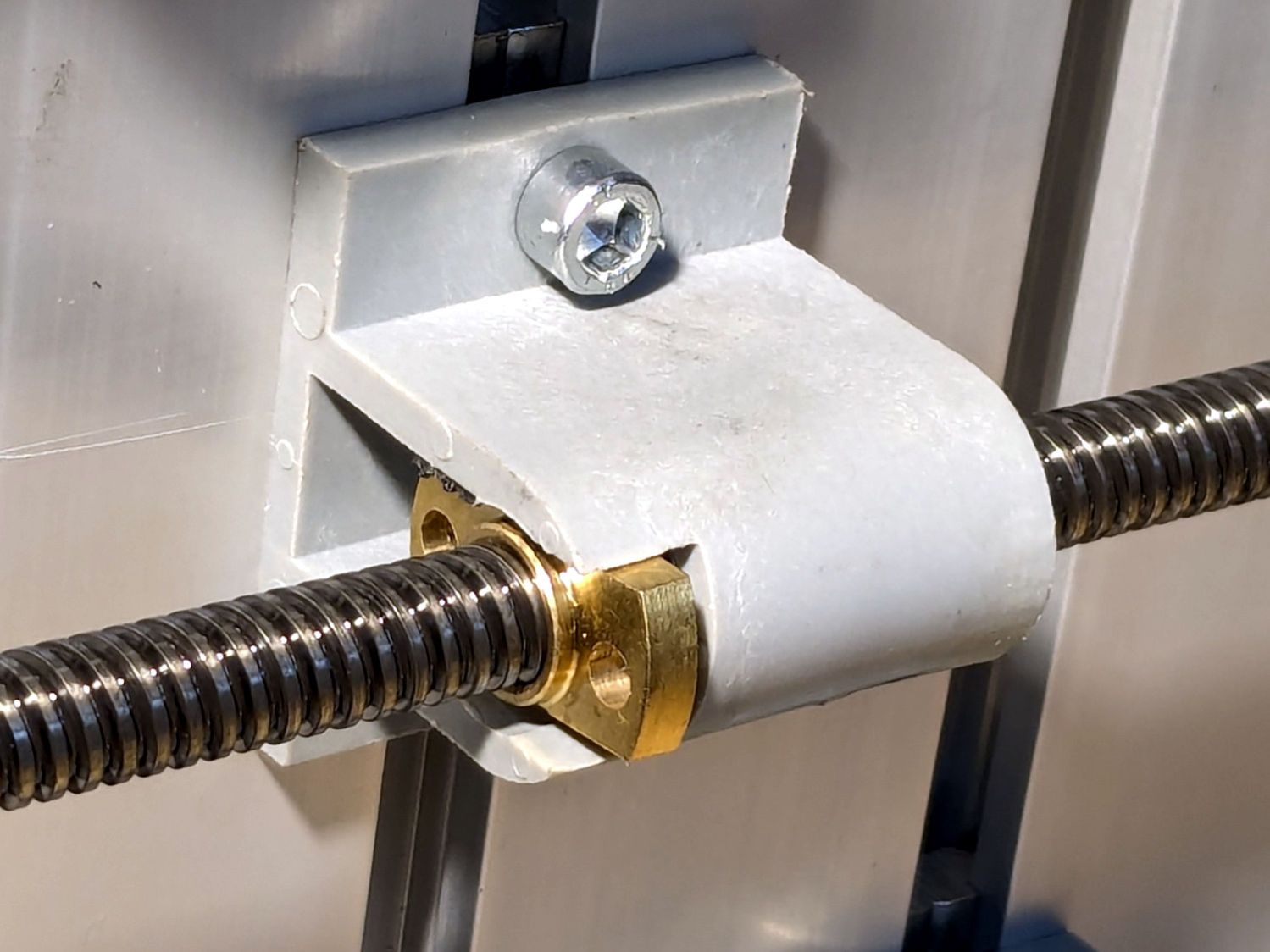
After fixing the X axis drive, the CNC-3018XL table moved properly again, so I measured its overall alignment:

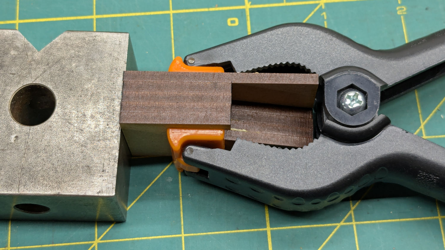
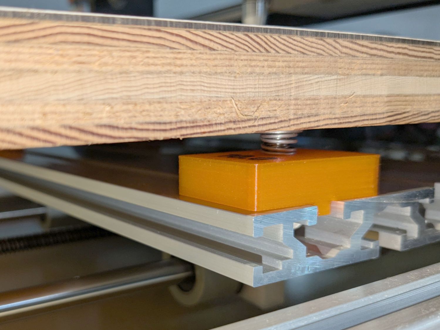
The +Y side (on the left in the photo, keeping in mind I’ve rotated the axes) turned out to be 0.7 mm too low, so I made a set of riser blocks to level the tabletop:

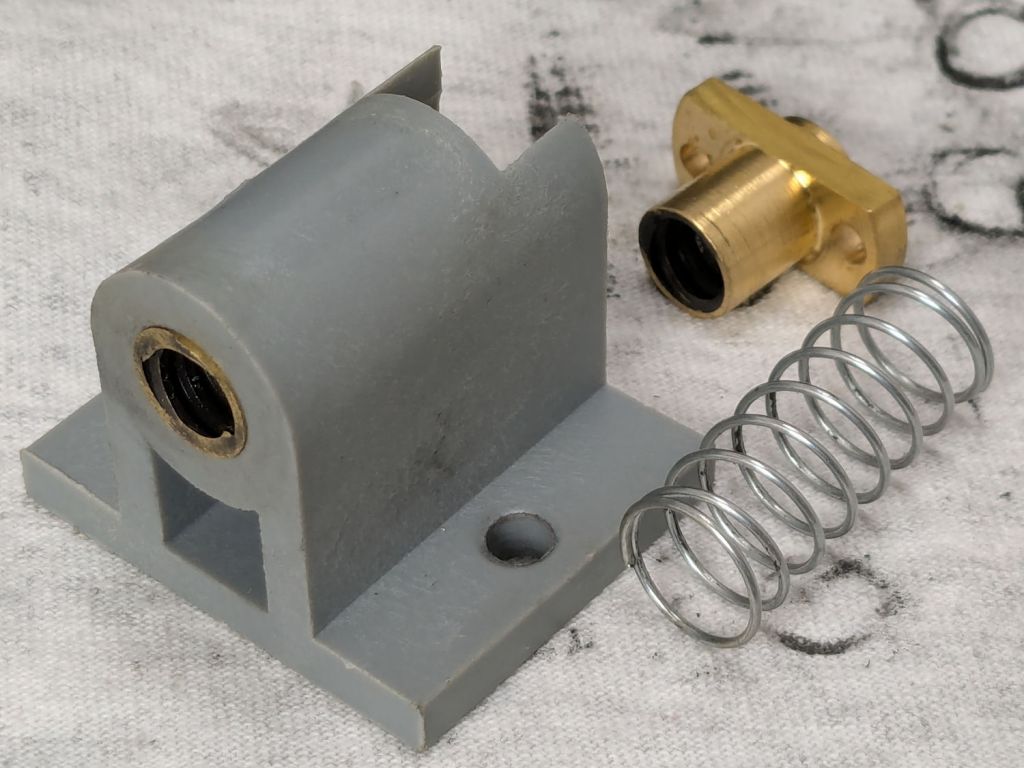
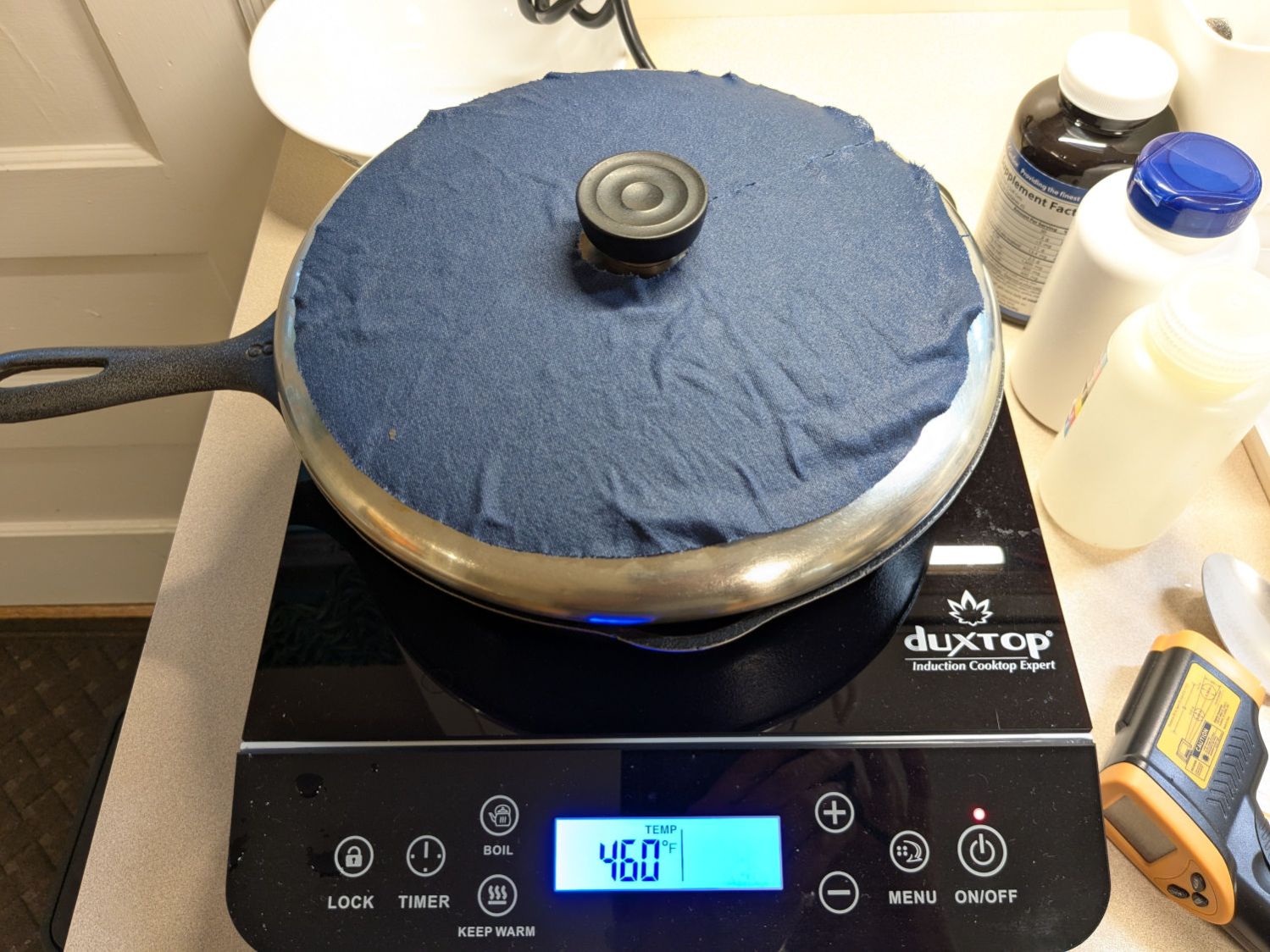
The 10 mm height would ram the tip of a Pilot pen about 10 mm below the tabletop surface, were it not for the spring-loaded pen holder:

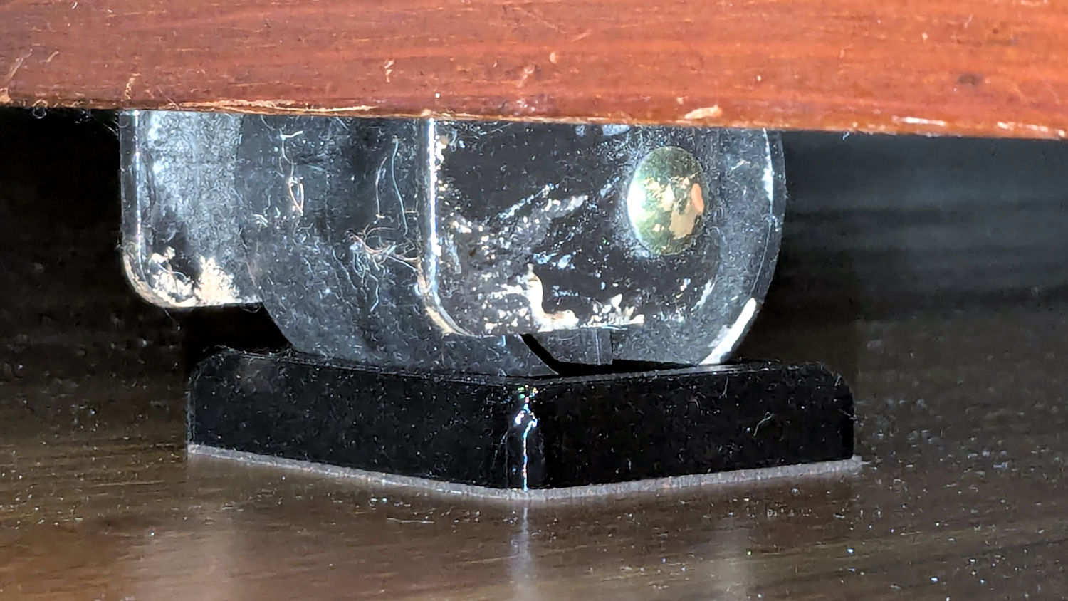
The 0.7 mm difference in height levels the tabletop:

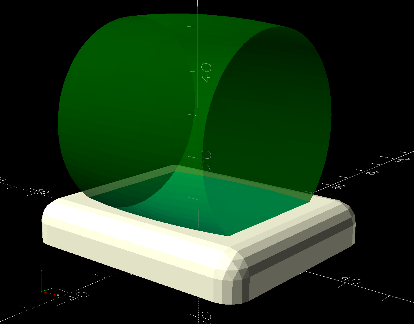
The OpenSCAD code produces an SVG outline I intended to use for a foam pad, but then I found a quartet of springs that worked even better:
So it’s now aligned within ±0.3-ish mm across the surface, with the unflatness of a slab cut from a 1955-era Formica kitchen countertop accounting for most of the difference in a swale from Quadrant III across the origin to Quadrant I.
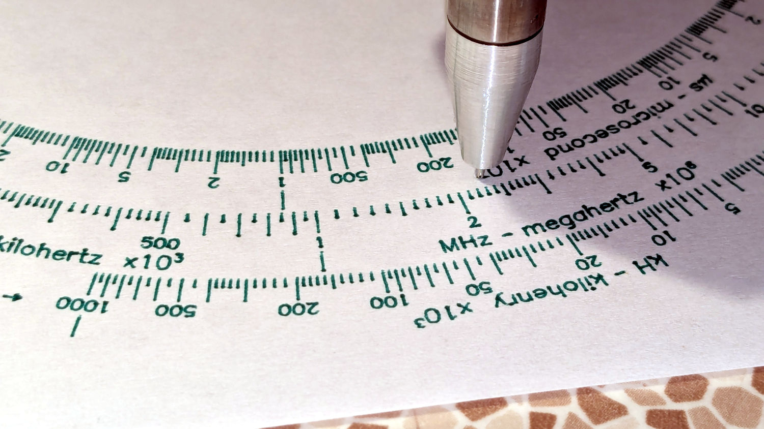
Which a check plot using an old file shows will be Flat Enough for my simple needs:
Having the camera alignment remain exactly spot on came as a pleasant surprise:
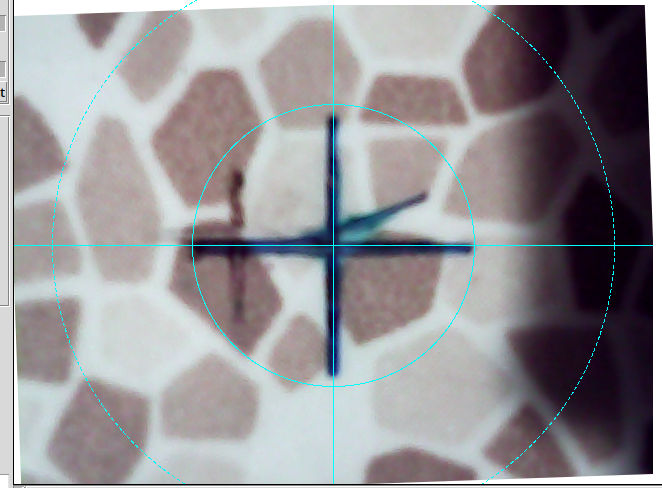
The faded cross to the left came from the table’s previous position; there’s no positive index between the countertop slab and the underlying T-slots.
Part of the motivation for these blocks was to verify PrusaSlicer automagically handles filament / color changes between two objects, as long as OpenSCAD hasn’t unioned them as part of a common transformation. Not having to cut out the socket around the text simplifies the code from what I’d been doing with previous objects.
The OpenSCAD source code as a GitHub Gist:
| // CNC 3018 table riser blocks | |
| // Ed Nisley – KE4ZNU | |
| // 2025-06-29 | |
| include <BOSL2/std.scad> | |
| Layout = "Show"; // [Show,Build,Outlines] | |
| /* [Hidden] */ | |
| HoleWindage = 0.2; | |
| Protrusion = 0.1; | |
| BlockOA = [40.0,30.0,10.0]; // riser block size | |
| SlotBlock = [8.0,BlockOA.y,3.0]; // alignment in slot | |
| BoltOD = 6.0 + HoleWindage; // central bolt | |
| LogoFont = "Fira Sans Condensed:style=SemiBold"; | |
| LogoSize = 7.5; | |
| LogoColor = "Red"; | |
| LogoThick = 0.4; | |
| //———- | |
| // Define Shapes | |
| module Riser(thick=1,matl="Block") { | |
| LogoText = format_fixed(thick,1); | |
| if (matl == "Text" || matl == "All") | |
| right(BlockOA.x/4) zrot(90) | |
| color(LogoColor) | |
| up(thick + SlotBlock.z + ((matl == "All") ? 0.01 : 0)) | |
| text3d(LogoText,LogoThick + ((matl == "All") ? 0.01 : 0),LogoSize,LogoFont, | |
| anchor=TOP,atype="ycenter"); | |
| if (matl == "Block" || matl == "All") | |
| difference() { | |
| cuboid(SlotBlock,$fn=8*3,anchor=BOTTOM,rounding=2.0,except=[BOTTOM,TOP]) position(TOP) | |
| cuboid(BlockOA,$fn=8*3,anchor=BOTTOM,rounding=2.0,except=[BOTTOM,TOP]); | |
| down(Protrusion) | |
| zrot(180/6) | |
| cyl(2*BlockOA.z,d=BoltOD,$fn=6,anchor=BOTTOM,circum=true); | |
| } | |
| } | |
| //———- | |
| // Build things | |
| if (Layout == "Show") | |
| down(SlotBlock.z) | |
| Riser(BlockOA.z,matl="All"); | |
| if (Layout == "Outlines") { | |
| projection(cut=false) | |
| Riser(BlockOA.z,matl="Block"); | |
| } | |
| if (Layout == "Build") { | |
| up(BlockOA.z + SlotBlock.z) xrot(180) | |
| Riser(BlockOA.z,matl="Block"); | |
| up(BlockOA.z + SlotBlock.z) xrot(180) | |
| Riser(BlockOA.z,matl="Text"); | |
| } |