The Smell of Molten Projects in the Morning

Ed Nisley's Blog: Shop notes, electronics, firmware, machinery, 3D printing, laser cuttery, and curiosities. Contents: 100% human thinking, 0% AI slop.

Category: Machine Shop

Mechanical widgetry

  • Sena PS410 Serial Server: Shelf with Calculations

    A crude shelf bandsawed from a plank moves the Sena PS410 serial server and an old Ethernet switch off the bench:

    Serial server shelf - front
    Serial server shelf – front

    The brackets holding it to the studs came from a 2×4 inch scrap:

    Serial server shelf - rear
    Serial server shelf – rear

    Obviously, the Basement Laboratory lacks stylin’ home decor.

    None of which would be worth mentioning, except for some Shop Calculations scrawled on the 2×4:

    Wood shop calculations
    Wood shop calculations

    It’s in my handwriting, although whatever it related to is long gone.

    Trigonometry FTW!

  • Snowblower Muffler Bracket

    After three years, the bracket locking the snowblower’s muffler bolts broke, but this time I saw the bolt pop out of the muffler, fall to the driveway, and lie there sizzling in the slush. I tightened the remaining bolt and completed the mission.

    The OEM bracket was thin sheet metal and broke across one bolt hole under the head. I sawed a rectangle out of a defunct PC case, then drilled clearance holes:

    Snowblower muffler - drilling bracket
    Snowblower muffler – drilling bracket

    Bending two corners upward locks the bolt heads in position. I started the bends by clamping the bracket in the bench vise and whacking the corners, then finishing the job with a drift punch after installing it:

    Snowblower muffler installed
    Snowblower muffler installed

    Of course, I renewed the Never-Seez on the bolt threads; they obviously weren’t corroded in place!

    For whatever it’s worth, the many spot welds joining the top bracket to the muffler are doing just fine.

  • Vape Cartridge

    Being the kind of guy who lives under a rock, I thought this thing lying at the end of the driveway might be a USB widget:

    Vape cartridge - side
    Vape cartridge – side

    But the contacts are all wrong:

    Vape cartridge - contacts
    Vape cartridge – contacts

    It has an opening on the other end:

    Vape cartridge - exhaust port
    Vape cartridge – exhaust port

    An easy teardown produces a yard sale of parts:

    Vape cartridge - components
    Vape cartridge – components

    The fiber snippet inside the coil carries the same sickly sweet scent as exhaled by passing vapers.

    Some casual searching suggests it’s a Juul Vape Pod. The Juul site insists on lower browser armor than I’m willing to grant it; you’re on your own.

    The heating coil press-fits into slots cut in the contacts:

    Vape cartridge - heater and contacts
    Vape cartridge – heater and contacts

    It’s about 1 Ω cold, so I foolishly assume there’s a current limiter somewhere in the circuitry.

    The little steel tube goes into the Tray o’ Cutoffs, where it might come in handy some day, the debris hits the trash, and I washed my hands up to the elbows.

    Ya learn something new every day around here and, obviously, I must get out more …

  • MPCNC: Linear Bearing Pen Holder

    The simplest way to push a pen (or similar thing) downward with constant force may be to hold it in a linear bearing with a weight on it, so I gimmicked up a proof-of-concept. The general idea is to mount the pen so its axis coincides with the DW660 spindle, so as to have the nib trace the same path:

    DW660 Pen Holder - unweighted
    DW660 Pen Holder – unweighted

    The puck mimics the shape of the DW660 snout closely enough to satisfy the MPCNC’s tool holder:

    DW660 Pen Holder - Slic3r
    DW660 Pen Holder – Slic3r

    The pen holder suffers from thin walls constrained by the 10 mm (-ish) pen OD and the 12 mm linear bearing ID, to the extent the slight infill variations produced by the tapered pen outline change the OD. A flock of 16 mm bearings, en route around the planet even as I type, should provide more meat.

    In any event, 3D printing isn’t noted for its perfect surface finish, so I applied an epoxy layer and rotated the holder as it cured:

    DW660 Pen Holder - epoxy coating
    DW660 Pen Holder – epoxy coating

    After letting it cure overnight, I ran a lathe tool along the length to knock down the high spots and set the OD to 11.9+ mm. Although the result turns out to be a surprisingly nice fit in the bearing, there’s no way epoxy can sustain the surface load required for the usual precision steel-on-steel fit.

    A plastic pen in a plastic holder weighs 8.3 g, which isn’t quite enough to put any force on the paper. Copper weighs 9 g/cm³ = 9 mg/mm³ and 10 AWG wire is 2.54 mm OD = 5 mm², so it’s 45 mg/mm: to get 20 g, chop off 450 mm of wire.

    I chopped off a bit more than that, straightened it, annealed it, and wound it around a random contestant from the Bucket o’ Sticks with an OD just over the pen OD:

    DW660 Pen Holder - copper weight forming
    DW660 Pen Holder – copper weight forming

    The helix is 13.5 mm down the middle of the turns and 14 turns long (trimmed of the tail going into the chuck and fudging the tail sticking out as a partial turn), so it’s 593 mm long and should weigh 26.7 g. It actually weighs 27.6 g: close enough.

    Which is enough to overcome stiction due to the holder’s surface roughness, but the mediocre epoxy-on-balls fit allows the pen point to wander a bit too much for good results.

    The prospect of poking precise holes into 16 mm drill rod seems daunting, but, based on what I see here, it will produce much better results: rapid prototyping FTW!

    The OpenSCAD source code as a GitHub Gist:

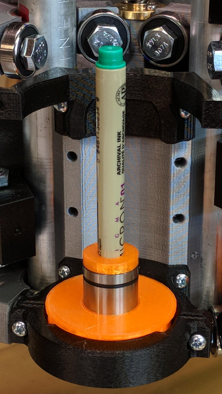
    // MPCNC Pen Holder for DW660 Mount
    // Ed Nisley KE4ZNU – 2018-03-05
    Layout = "Build"; // Build, Show
    // Puck, MountBase, BuildBase
    // Pen, PenAdapter, BuildAdapter
    /* [Extrusion] */
    ThreadThick = 0.25; // [0.20, 0.25]
    ThreadWidth = 0.40; // [0.40]
    /* [Hidden] */
    Protrusion = 0.1; // [0.01, 0.1]
    HoleWindage = 0.2;
    inch = 25.4;
    function IntegerMultiple(Size,Unit) = Unit * ceil(Size / Unit);
    ID = 0;
    OD = 1;
    LENGTH = 2;
    //- Adjust hole diameter to make the size come out right
    module PolyCyl(Dia,Height,ForceSides=0) { // based on nophead's polyholes
    Sides = (ForceSides != 0) ? ForceSides : (ceil(Dia) + 2);
    FixDia = Dia / cos(180/Sides);
    cylinder(r=(FixDia + HoleWindage)/2,h=Height,$fn=Sides);
    }
    //- Dimensions
    WallThick = 3.0; // minimum thickness / width
    Screw = [3.0,7.0,25.0]; // holding it all together, OD = washer
    Insert = [3.0,4.4,4.5]; // brass insert
    Bearing = [12.0,21.0,30.0]; // LM12UU bearing body, ID = rod OD
    PenTravel = 5.0; // vertical pen travel allowance
    NumSides = 8*4; // cylinder facets
    //—–
    // Define shapes
    //– Sakura Micron fiber-point pen
    ExpRP = 0.30; // expand critical sections (by radius)
    //– pen locates in holder against end of outer body
    PenOutline = [
    [0,0], // 0 fiber pen tip
    [0.6/2,0.0],[0.6/2,0.9], // 1 … cylinder
    [1.5/2,0.9],[1.5/2,5.3], // 3 tip surround
    [4.7/2,5.8], // 5 chamfer
    [4.9/2,12.3], // 6 nose
    // [8.0/2,12.3],[8.0/2,13.1], // 7 latch ring
    // [8.05/2,13.1],[8.25/2,30.5], // 9 actual inner body
    [8.4/2 + ExpRP,12.3],[8.4/2 + ExpRP,30.5], // 7 inner body – clear latch ring
    [9.5/2 + ExpRP,30.9], // 9 outer body – location surface!
    [9.8/2 + ExpRP,60.0], // 10 outer body – length > Body
    [7.5/2,60.0], // 11 arbitrary length, much longer than bearing
    [7.5/2,59.0], // 12 end of reservoir
    [0,59.0] // 13 fake reservoir
    ];
    PenNose = PenOutline[6][1];
    PenLocate = PenOutline[9][1];
    // Basic shape of DW660 snout fitting into the holder
    // Lip goes upward to lock into MPCNC mount
    Snout = [44.6,50.0,9.6]; // LENGTH = ID height
    Lip = 4.0; // height of lip at end of snout
    Key = [Snout[ID],25.7,Snout[LENGTH] + Lip]; // rectangular key
    module DW660Puck() {
    cylinder(d=Snout[OD],h=Lip/2,$fn=NumSides);
    translate([0,0,Lip/2])
    cylinder(d1=Snout[OD],d2=Snout[ID],h=Lip/2,$fn=NumSides);
    cylinder(d=Snout[ID],h=Lip + Snout[LENGTH],$fn=NumSides);
    intersection() {
    translate([0,0,0*Lip + Key.z/2])
    cube(Key,center=true);
    cylinder(d=Snout[OD],h=Lip + Key.z,$fn=NumSides);
    }
    }
    module MountBase() {
    difference() {
    DW660Puck();
    translate([0,0,-Protrusion])
    PolyCyl(Bearing[OD],2*Bearing[LENGTH],NumSides);
    }
    }
    //– Sakura drawing pen body & polygon shape
    module Pen() {
    rotate_extrude($fn=NumSides)
    polygon(points=PenOutline);
    polygon(points=PenOutline);
    }
    //– Pen holder
    AdapterRing = [Bearing[ID],Bearing[OD],4.0];
    AdapterOAL = Bearing[LENGTH] + PenTravel + AdapterRing[LENGTH];
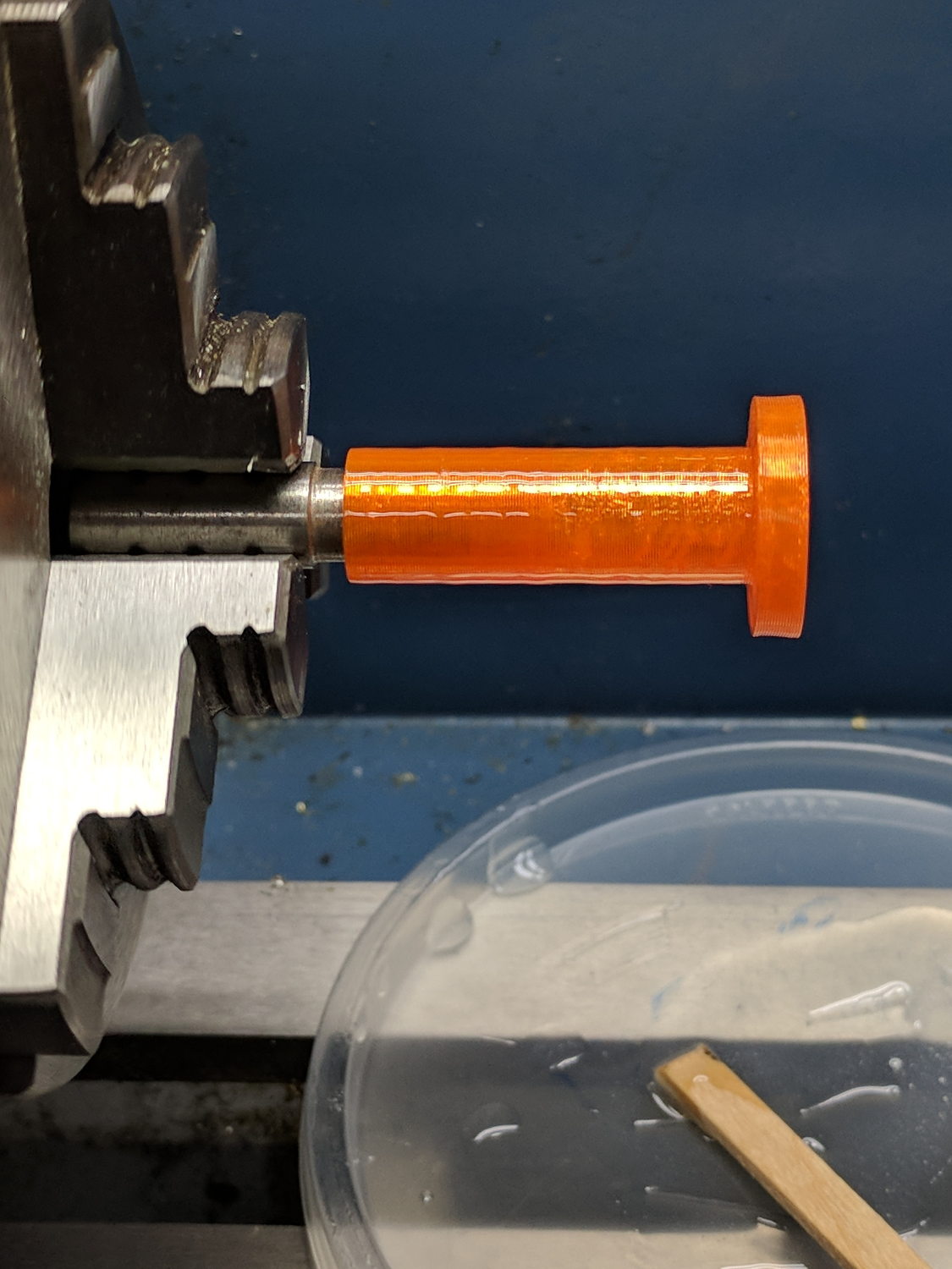
    module PenAdapter() {
    difference() {
    union() {
    PolyCyl(Bearing[ID],AdapterOAL,NumSides);
    translate([0,0,AdapterOAL – AdapterRing[LENGTH]])
    cylinder(d=AdapterRing[OD],h=AdapterRing[LENGTH],$fn=NumSides);
    }
    translate([0,0,-(PenNose + Protrusion)])
    Pen();
    }
    }
    //—–
    // Build it
    if (Layout == "Puck")
    DW660Puck();
    if (Layout == "MountBase")
    MountBase();
    if (Layout == "Pen")
    Pen();
    if (Layout == "PenAdapter")
    PenAdapter();
    if (Layout == "Show")
    MountBase();
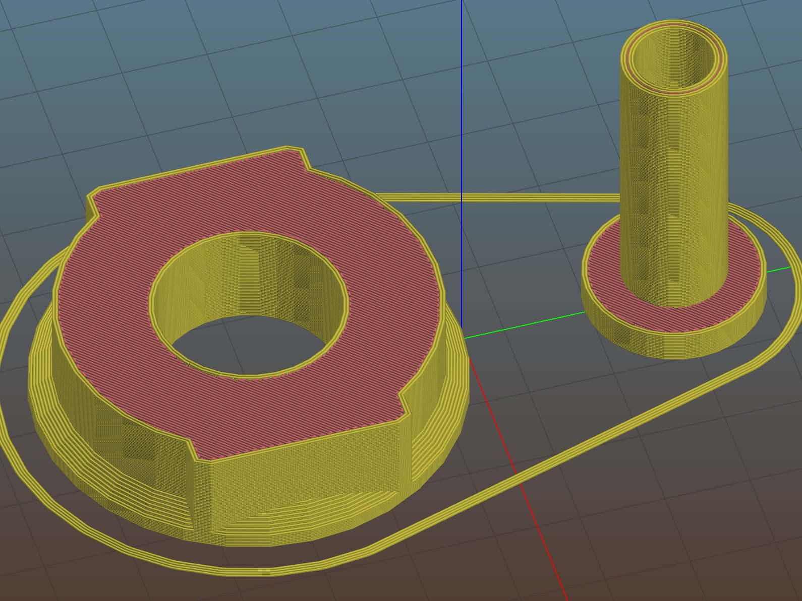
    if (Layout == "BuildBase" || Layout == "Build")
    translate([0,-Snout[OD]/2,0])
    MountBase();
    if (Layout == "BuildAdapter" || Layout == "Build")
    translate([0,Snout[OD]/2,AdapterOAL])
    rotate([180,0,0])
    PenAdapter();
  • MPCNC: USB Camera Alignment

    Adding a lock screw to the camera mount stabilized the camera-to-spindle offset enough to make calibration meaningful. Mark the spot directly under the camera:

    bCNC - Camera - hot glue align
    bCNC – Camera – hot glue align

    Then mark the spot directly under the spindle, perhaps by poking a small cutter into the tape, measure the XY distances between the two center points, and use bCNC’s camera registration process to set the camera offset.

    With those numbers in place, switching to the tool view (the green button with the end mill to the right in the ribbon bar) puts the camera at the spindle location:

    bCNC - Spindle - hot glue align
    bCNC – Spindle – hot glue align

    The view from outside shows the relation between those two pieces of tape:

    MPCNC - USB camera-to-spindle alignment
    MPCNC – USB camera-to-spindle alignment

    Now I can align the camera view to a fixture position and be (reasonably) sure the spindle will automagically align to the same XY coordinate when I switch to the “tool” view. Seems to work well in preliminary tests, anyhow.

  • MPCNC: USB Camera Mount With Lock Screw

    It turned out the previous version of the USB camera mount lacked sufficient griptivity to hold the ball’s position against even moderate bumps, so the upper “half” is now tall enough to hold a lock screw directly over the ball:

    MPCNC - USB Camera mount - lock screw - Slic3r
    MPCNC – USB Camera mount – lock screw – Slic3r

    It doesn’t look much different:

    MPCNC - USB Camera Mount - lock screw
    MPCNC – USB Camera Mount – lock screw

    A view from the other side:

    USB Camera - lock screw mount
    USB Camera – lock screw mount

    The previous iterations used Genuine 3M foam tape, which seemed too flexy for comfort. This one sits on a bed of hot melt glue and is absolutely rigid. We’ll see how long it survives.

    Tightening the cap screw requires needle-nose pliers, because the whole affair has no room for a hex key.

    The OpenSCAD source code as a GitHub Gist:

    // MPCNC USB Camera Mount
    // Ed Nisley KE4ZNU – 2018-02-22
    Layout = "Build"; // Build, Show
    /* [Extrusion] */
    ThreadThick = 0.25; // [0.20, 0.25]
    ThreadWidth = 0.40; // [0.40]
    /* [Hidden] */
    Protrusion = 0.1; // [0.01, 0.1]
    HoleWindage = 0.2;
    inch = 25.4;
    function IntegerMultiple(Size,Unit) = Unit * ceil(Size / Unit);
    ID = 0;
    OD = 1;
    LENGTH = 2;
    //- Adjust hole diameter to make the size come out right
    module PolyCyl(Dia,Height,ForceSides=0) { // based on nophead's polyholes
    Sides = (ForceSides != 0) ? ForceSides : (ceil(Dia) + 2);
    FixDia = Dia / cos(180/Sides);
    cylinder(r=(FixDia + HoleWindage)/2,h=Height,$fn=Sides);
    }
    //- Dimensions
    WallThick = 3.0; // minimum thickness / width
    CameraStalk = [6.0 + 1.0,10.0 + HoleWindage,4.0]; // stalk OD, ball OD, stalk length
    CameraAngle = -5; // stalk tilt, negative = downward
    Screw = [3.0,7.0,25.0]; // holding it all together, OD = washer
    Insert = [3.0,4.4,4.5]; // brass insert
    Pusher = Insert[LENGTH] / 2; // plastic locking snippet
    UpperThick = IntegerMultiple(CameraStalk[OD]/2 + Insert[LENGTH] + Pusher + WallThick,ThreadThick);
    LowerThick = Screw[LENGTH] – UpperThick;
    MountBlock = [24.0,20.0,LowerThick + UpperThick];
    echo(str("Block: ",MountBlock));
    NumSides = 6*4;
    //—–
    // Define shapes
    // Camera mount, enlongated for E-Z differencing
    // Origin at center of ball, stalk along +X
    module Camera() {
    union() {
    sphere(d=CameraStalk[OD],$fn=NumSides);
    rotate([0,90 – CameraAngle,0])
    PolyCyl(CameraStalk[ID],3*CameraStalk[LENGTH],NumSides);
    }
    }
    // Mount block with all the cutouts
    // Ball centerline on XY plane = block split line
    module Mount(Half="All") {
    Rounding = 2.0; // corner radius
    ZShift = // block shift to remove unwanted half
    (Half == "Upper") ? -MountBlock.z/2 – 0*UpperThick :
    (Half == "Lower") ? MountBlock.z/2 + 0*LowerThick :
    2*MountBlock.z; // … want both halves, remove none
    difference() {
    hull()
    for (i=[-1,1], j=[-1,1]) {
    translate([i*(MountBlock.x/2 – Rounding),j*(MountBlock.y/2 – Rounding),(UpperThick – Rounding)])
    sphere(r=Rounding,$fn=3*4);
    translate([i*(MountBlock.x/2 – Rounding),j*(MountBlock.y/2 – Rounding),-(LowerThick – Rounding)])
    sphere(r=Rounding,$fn=3*4);
    }
    for (j=[-1,1])
    translate([-MountBlock.x/4,j*MountBlock.y/4,-(LowerThick + Protrusion)]) {
    PolyCyl(Insert[OD],Insert[LENGTH] + Protrusion,6);
    PolyCyl(Insert[ID],2*MountBlock.z,6);
    }
    translate([MountBlock.x/2 – (CameraStalk[OD]/2 + CameraStalk[LENGTH]),0,0]) {
    Camera();
    translate([0,0,UpperThick – (Insert[LENGTH] + WallThick)])
    PolyCyl(Insert[OD],Insert[LENGTH] + WallThick,6);
    PolyCyl(Insert[ID],2*UpperThick,6);
    }
    translate([0,0,ZShift])
    cube([2*MountBlock.x,2*MountBlock.y,MountBlock.z],center=true);
    }
    }
    //—–
    // Build it
    if (Layout == "Show")
    Mount("All");
    if (Layout == "Build") {
    translate([0,0.75*MountBlock.y,UpperThick])
    rotate([180,0,0])
    Mount("Upper");
    translate([0,-0.75*MountBlock.y,LowerThick])
    rotate([0,0,0])
    Mount("Lower");}
  • MPCNC: Makerbot-style Endstop Switch Spring Constant

    Using a lever-arm switch as a tool length probe works surprisingly well:

    MPCNC Tool Length Probe - Plotter Pen
    MPCNC Tool Length Probe – Plotter Pen

    However, probing a pen mounted in a compliant holder means the actual trip point depends on the relative spring constants. Having measured the pen holder’s 100 g/mm spring constant by poking a scale with the pen, I did much the same thing with the endstop Z-axis Autolevel probe:

    IMG_20180305_161831 - MPCNC - Z Autolevel probe force.jpg

    Which produced a similar graph:

    MB Endstop Switch - spring constant
    MB Endstop Switch – spring constant

    The force increases linearly at 30 g/mm up to the trip point, drops by maybe 16 grams, then increases linearly again.

    Obviously, the “constant” applies only to switches on MBI-style endstops in the lot I happen to have, but given the ubiquity of parts from the usual eBay sellers, any identical lever switches may have the same “constant”:

    Endstop lever switch - detail
    Endstop lever switch – detail

    Your mileage will vary, fer shure.

    Poking a pen into a similar switch used as a tool setter means the Z-axis coordinate of the trip point will depend on the opposing springs. That’s unlike the situation with a cutter mounted in the DW660 spindle, which (by definition) shouldn’t move in response to the pressure from a little bitty switch.

    Eyeballing the graph, the switch travels 2.2 mm to the trip point, where it exerts 64 g of force. The pen holder opposes that force and therefore deflects (64 g) / (100 g/mm) = 0.64 mm just before the switch trips: the trip point will be the same as with a rigid tool, but the tool’s Z axis coordinate will be 0.64 mm lower.

    I’d been touching off pens in the springy holder, with enough pressure to draw a decent line. Setting Z=0 with the holder deflected upward by 0.3 mm means the pen first touches the height probe at Z=+0.3 and the switch trips at Z=-0.3 mm (-ish), making the force on the paper 60 g, rather than the 30 g I expected.

    I think the pen plots worked out pretty well, despite not getting the numbers and, thus, pen positions, quite right.