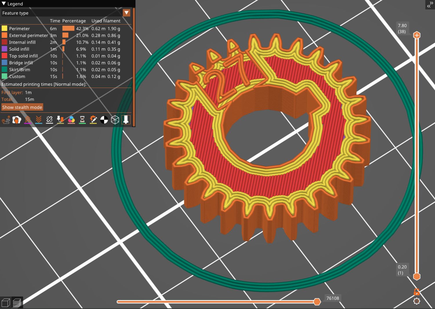
Because the BOSL2 library includes a gear generator, I can now avoid creating a gear outline in Inkscape and importing it into my stacked change gear generator.
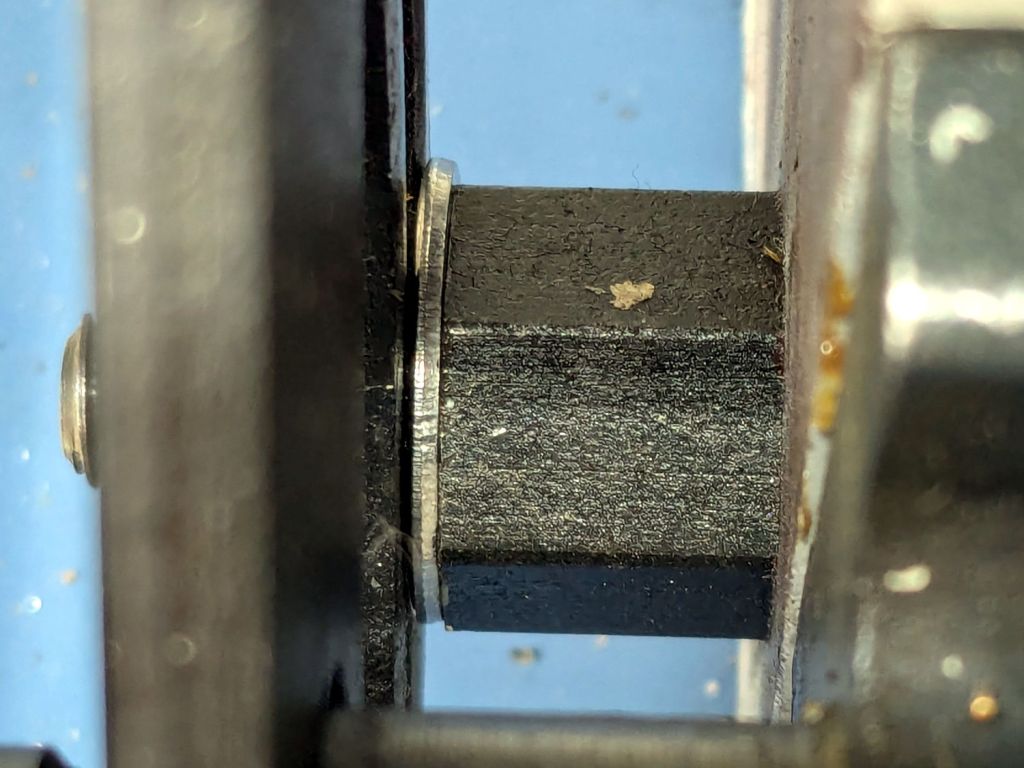
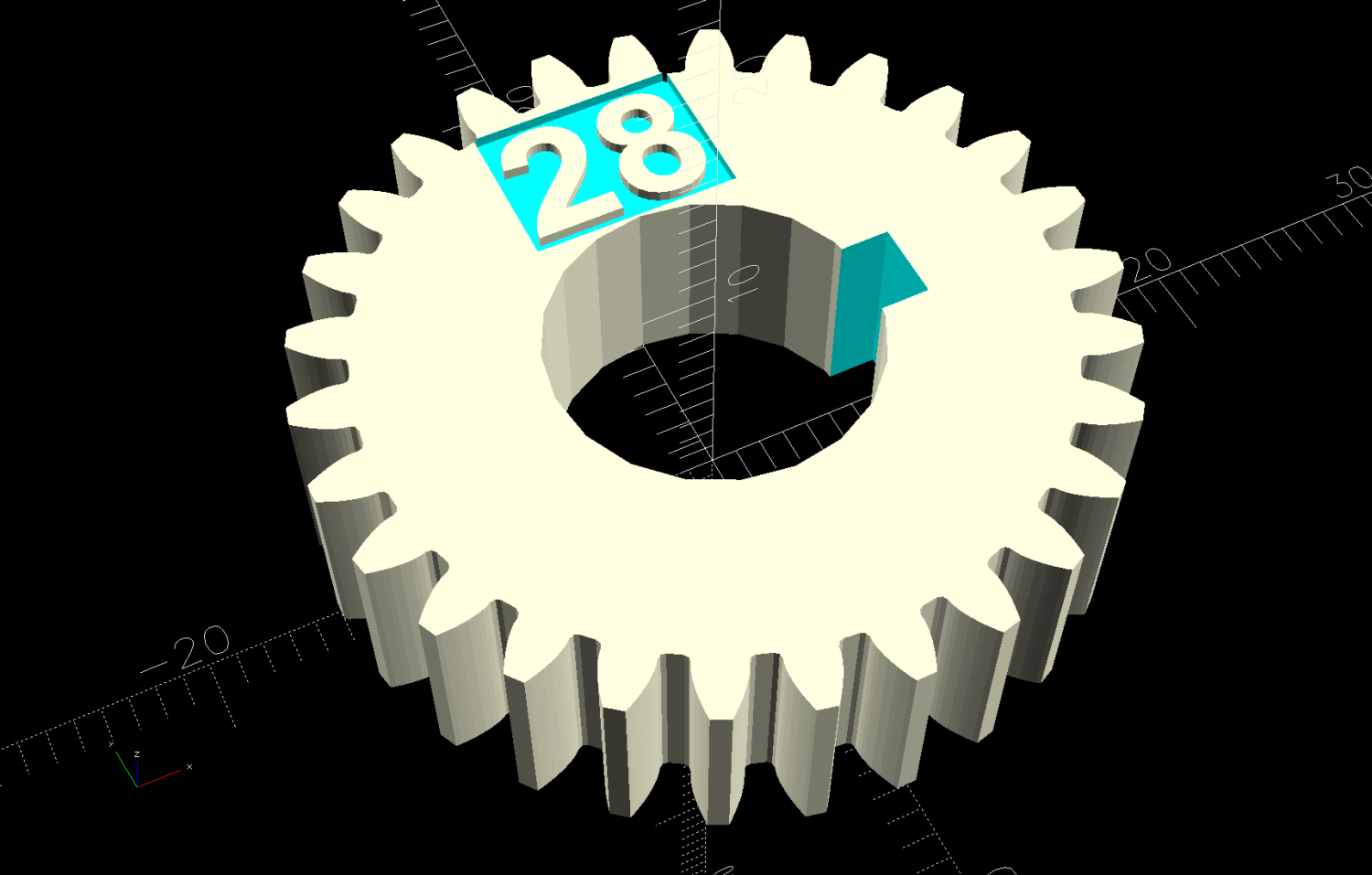
The labels now snuggle closer to the shaft and (barely) fit on smaller gears:
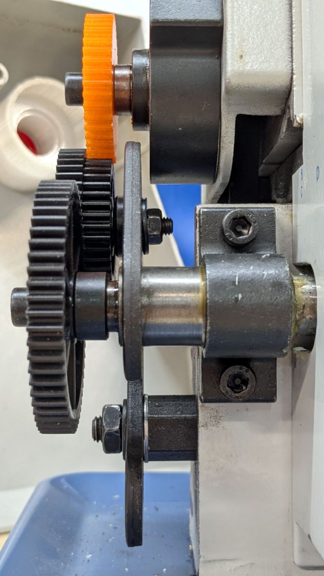
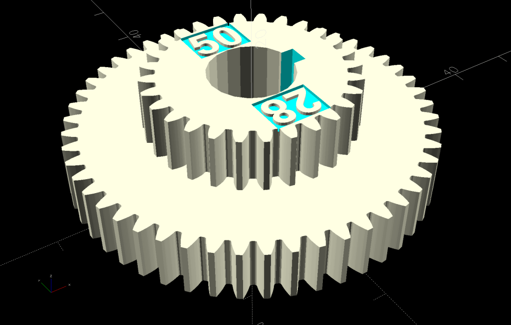
The stacked B-C gears for the jack shaft work as before, with both labels on the top gear:

The admittedly flimsy motivation for all this was to make a 28 tooth gear to cut a 0.9 mm pitch, thus filling an obvious hole in the gear table.
My collection of gears could do 21-60-81-50, but the 81 T gear collides with the screw holding the 21 T gear. Rearranging it to 21-50-81-60 showed the B-C gears exceeded the space available.
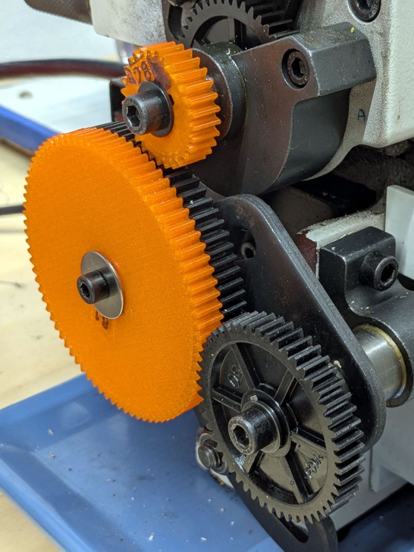
Because it’s all ratios and a 28 T gear is 4/3 bigger than 21 T, reducing the rest of the train by 3/4 should work. In fact, it produced a reasonable 28-80-81-50 chain:
The fact that I do not anticipate ever needing to cut a 0.9 mm pitch has nothing whatsoever to do with it; that gear will surely come in handy for something.
While I was at it, I made a 27 T gear, because 27 = 21 × 9/7:
You can never have enough change gears. Right?
The OpenSCAD source code as a GitHub Gist:
| // LMS Mini-Lathe | |
| // Change gears with stacking | |
| // Ed Nisley – KE4ZNU | |
| // 2020-05 use Inkscape SVG gears | |
| // 2025-12 use BOSL2 gear generator | |
| include <BOSL2/std.scad> | |
| include <BOSL2/gears.scad> | |
| /* [Gears] */ | |
| TopGear = 0; // zero for single gear | |
| BottomGear = 28; | |
| /* [Hidden] */ | |
| ThreadThick = 0.20; | |
| HoleWindage = 0.2; | |
| Protrusion = 0.1; // make holes end cleanly | |
| /* [Dimensions] */ | |
| ShaftOD = 12.0; | |
| GearThick = 7.75; | |
| Keyway = [3.5,3.0,3*GearThick]; // x on radius, y on perim | |
| LegendEnable = (TopGear == 0 && BottomGear > 27) || (TopGear > 27); | |
| LegendThick = 2*ThreadThick; | |
| LegendZ = (TopGear ? 2*GearThick : GearThick) – LegendThick; | |
| LegendSize = 5; | |
| LegendRecess = [8,6,LegendThick]; | |
| LegendOffset = [0,LegendRecess.y/2 + ShaftOD/2 + HoleWindage,LegendZ + LegendRecess.z/2]; | |
| //———————– | |
| // Build it! | |
| union() { | |
| difference() { | |
| union() { | |
| spur_gear(mod=1,teeth=BottomGear,thickness=GearThick,shaft_diam=ShaftOD + HoleWindage,anchor=BOTTOM); | |
| if (TopGear) | |
| spur_gear(mod=1,teeth=TopGear,thickness=2*GearThick,shaft_diam=ShaftOD + HoleWindage,anchor=BOTTOM); | |
| } | |
| right(ShaftOD/2) | |
| down(Protrusion) | |
| cube(Keyway,anchor=CENTER+BOTTOM); | |
| if (LegendEnable) { | |
| translate(LegendOffset) | |
| cube(LegendRecess + [0,0,Protrusion],anchor=CENTER); | |
| if (TopGear) | |
| zrot(180) | |
| translate(LegendOffset) | |
| cube(LegendRecess + [0,0,Protrusion],anchor=CENTER); | |
| } | |
| } | |
| if (LegendEnable) | |
| translate([0,0,LegendZ – Protrusion]) | |
| linear_extrude(height=LegendThick + Protrusion,convexity=10) { | |
| translate([LegendOffset.x,LegendOffset.y]) | |
| text(text=str(BottomGear),size=LegendSize,font="Arial:style:Bold",halign="center",valign="center"); | |
| if (TopGear) | |
| zrot(180) | |
| translate([LegendOffset.x,LegendOffset.y]) | |
| text(text=str(TopGear),size=LegendSize,font="Arial:style:Bold",halign="center",valign="center"); | |
| } | |
| } |