Ed Nisley's Blog: Shop notes, electronics, firmware, machinery, 3D printing, laser cuttery, and curiosities. Contents: 100% human thinking, 0% AI slop.
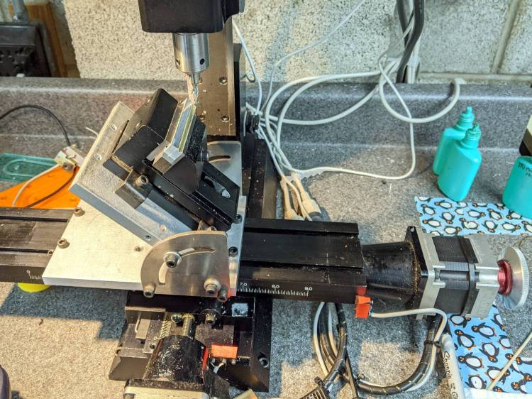
The need to gnaw a V groove into the side of two 60 mm aluminum bars led to this Sherline CNC mill setup:
Sherline Y-Axis Nut Mishap – setup
Milling the near end of the bars put the angle plate’s rear lock screw within a millimeter of the column; the vise fits in exactly one spot on the angle plate and that’s where the jaws must be.
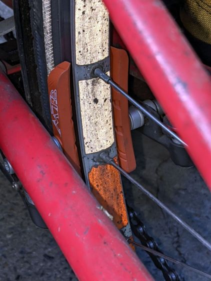
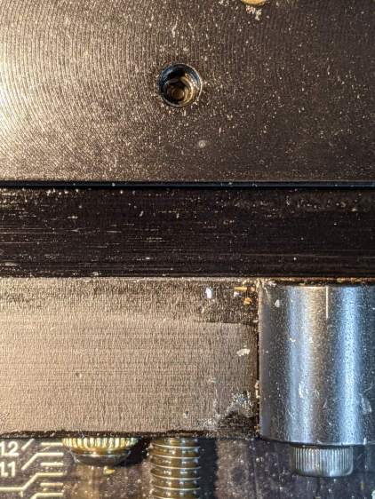
While controlling the mill with the Joggy Thing and some manual command entry, because it’s easier than real CNC programming, I overshot the near end and rammed the column with enough enthusiasm to dislodge the Y-axis leadscrew nut. An interlude of utter confusion ended with the backlash preload nut firmly jammed against the leadscrew coupler on the other end of travel:
Sherline Y-Axis Nut Mishap – stuck preload nut
The paper shreds show where the bellows formerly stuck on the Y axis stage.
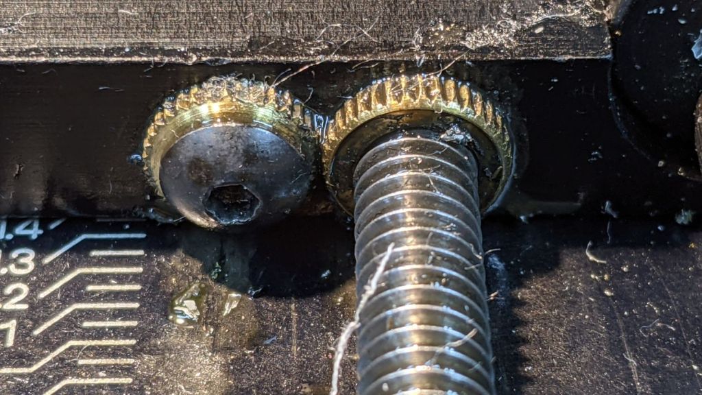
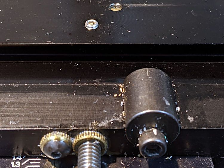
The backlash nut chewed off a few star lock gear teeth on its way out, as seen here just above where they mesh:
Sherline Y-Axis Nut Mishap – chewed star nut
It’s been quite a few years since I took the thing apart to replace the nuts, so I used the opportunity to lube the otherwise inacessible X axis leadscrew inside its table upside down on the bench.
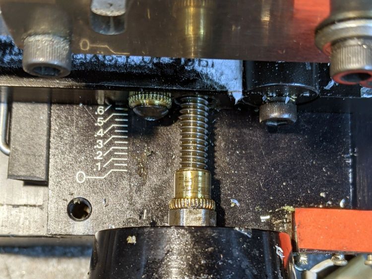
The setscrew locking the Y axis leadscrew nut in place heaves into view with the X axis table off:
Sherline Y-Axis Nut Mishap – setscrew
I thought about jamming it in place with a second 10-32 setscrew, but the ones on hand were just an itsy too long and collided with the X-axis table:
Sherline Y-Axis Nut Mishap – doubled setscrew
The thought of having the additional setscrew work loose, grind into the underside of the table, and require major surgery for recovery persuaded me to drop it back in the drawer.
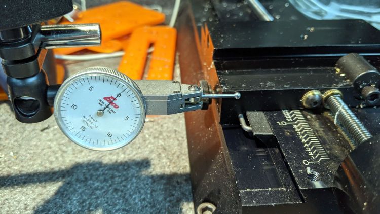
With everything in place, I adjusted the backlash (on both axes) down to a few mils:
Sherline Y-Axis Nut Mishap – backlash test
Tweaking the X axis preload nut under the table is not my idea of a good time, but it’s been quite a while since I had to do that.
Folding the new paper bellows and installing them took about as long as repairing the mill.
Milling the second V groove worked fine; all is right with the Sherline again.
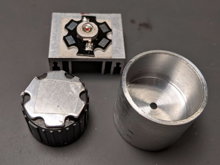
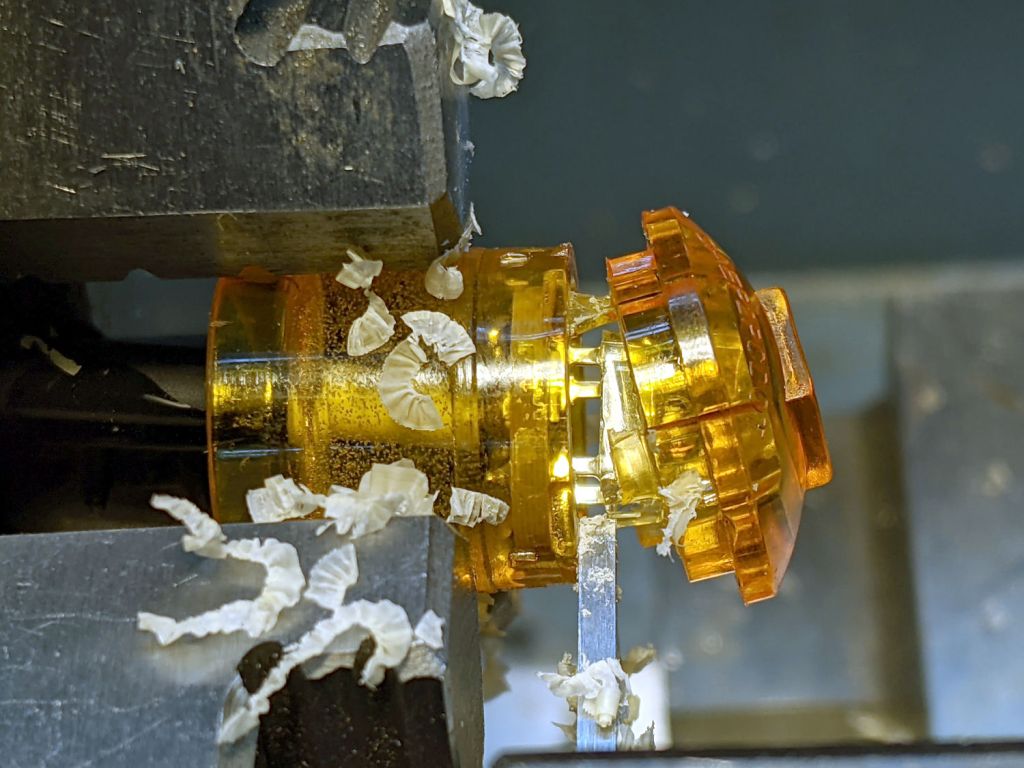
A pleasant evening at a virtual Squidwrench meeting produced the raw shape of the front end from a 1 inch aluminum rod:
1 W LED Running Light – heatsink raw
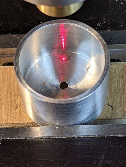
Trace the outline of the LED’s PCB inside the cylinder just for comfort, align to the center, and drill two holes with a little bit of clearance:
1 W LED Running Light – heatsink drilling
For the 24 AWG silicone wire I used, a pair of 2 mm holes 8.75 mm out from the center suffice:
1 W LED Running Light – heatsink fit
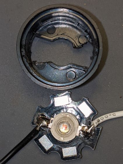
Gnaw some wire clearance in the lens holder:
1 W LED Running Light – wiring
Tap the central hole for an M3×0.5 screw, which may come in handy to pull the entire affair together.
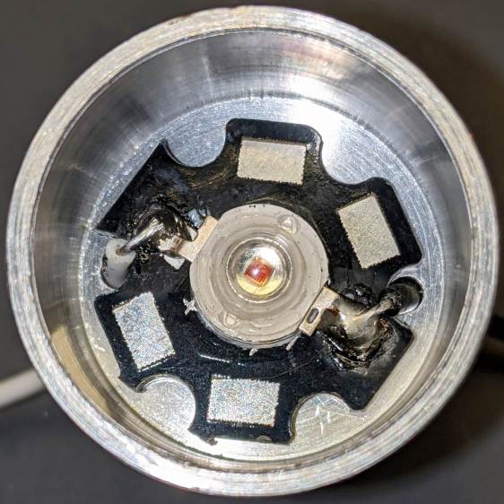
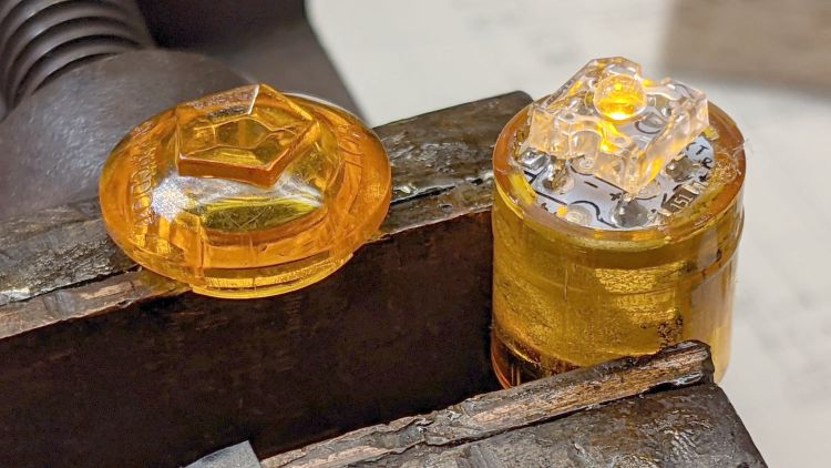
Epoxy the PCB onto the heatsink with the lens holder keeping it aligned in the middle:
1 W LED Running Light – heatsink clamp
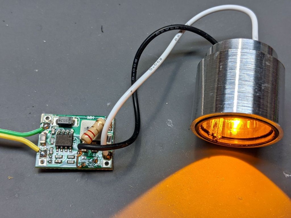
Then see how hot it gets dissipating 900 mW with 360 mA of current from a 2.2 Ω resistor:
1 W LED Running Light – heatsink test
As you might expect, it gets uncomfortably warm sitting on the bench, so it lacks surface area. The first pass will use a PVC cylinder for easy machining, but a full aluminum shell would eventually be a nice touch.
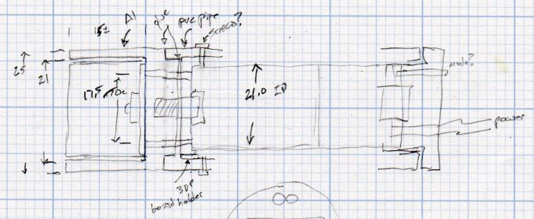
A doodle with some dimensions and aspirational features:
Running Light – 1 W LED case doodle
Even without a lens and blinkiness, it’s attention-getting!
In late May we deployed six sticky traps in and around the onion bed, attempting to reduce the number of Onion Fly maggots. By mid-June the sheets were covered with the shredded leaves Mary uses to mulch the onions, but half a dozen flies were out of action:
Sticky trap – 2021-06
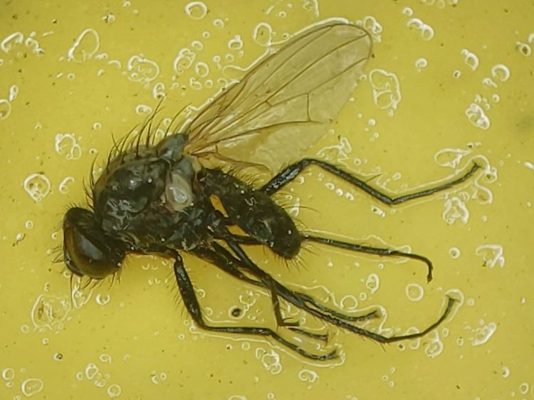
We’re pretty sure that’s what these things are:
Sticky trap – Onion Fly – 2021-06
They’re supposed to have red eyes, but being affixed to a sheet of snot for a few weeks doesn’t do the least bit of good for your eyes.
We replaced the sheets and left them in place until the end of July:
Sticky trap – 2021-07
The sheets took another half-dozen flies out of circulation, Mary began harvesting the onions, and observed it was the healthiest onion harvest she’s ever had.
We declared victory, removed the traps, and the remaining onions suffered considerable maggot damage over the next few weeks.
Anecdotally, it seems reducing the Onion Fly population by (what seems to be) a small amount and maintaining pressure on the population dramatically reduces the number of maggots available to damage the onion crop. At least for a single bed in a non-commercial setting.
The plural of anecdote is not anecdata, but we’ll try it again next year, leave the traps in place while the onions are in the ground, and see what happens.
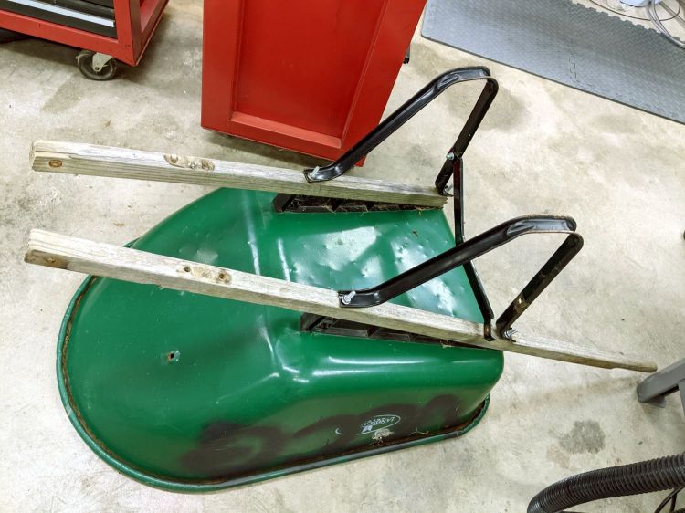
For reasons that should be obvious by now, I volunteered to rebuild a wheelbarrow used at the Vassar Community Garden plots. It spent all its time outdoors and one of the handles eventually broke off:
Wheelbarrow rebuild – old handles
I’d already removed the wheel and front strap, which were in good condition.
The new handles were undrilled, so I marked and drilled them with a nice brad-point bit to get clean holes:
Wheelbarrow rebuild – handle drilling
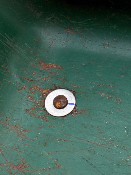
The metal “barrow” had cracked around the carriage bolts holding it to the frame, so I filed a quartet of fender washers to fit the square section under the heads:
Wheelbarrow rebuild – fender washer holes
After a false start, I marked the bolt heads and washers to line them up properly while tightening the nuts on the other end:
Wheelbarrow rebuild – fender washer installed
One front strut had gone missing, so I replaced it with a mashed-and-drilled section of ski pole:
Wheelbarrow rebuild – front strut
All in all, a few hours of Quality Shop Time interspersed with a few pleasant bike rides to various local stores, wherein I learned who doesn’t stock the necessary hardware.
Protip: Home Depot has the highest-entropy hardware assortment.
For the record, all the bolts have a 5/16-18 thread.
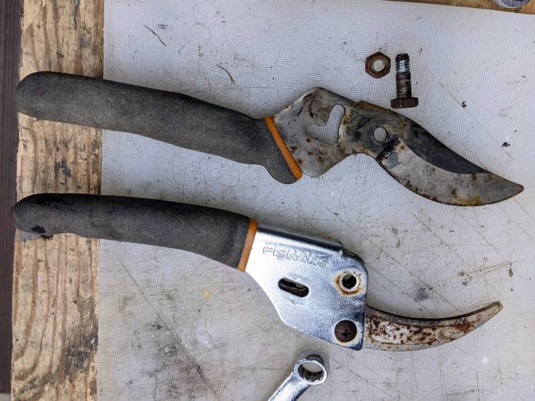
Mary found a rusted Fiskars bypass pruner in the trash pile near her Vassar Farms plot and brought it home for proper disposal. The nuts and screws responded to an overnight penetrating oil treatment and it came apart easily:
Fiskars bypass pruner – as found
The movable jaw may have once sported a PTFE coating, but it’s likely just a different steel alloy.
After scrubbing the pieces with an abrasive pad, a little diamond filing, and (at the insistence of the Squidwrench chorus) some Dremel wire-wheel action, it looks almost new:
Fiskars bypass pruner – restored
The blades sport a few nicks from their previous life, but work well enough.
The cut is just in front of the PCB and went slowly to avoid clobbering the SMD resistors very near the edge.
The cataract turned out to be crud adhered to the LED lens:
Side Marker E – LED cataract
Brutal surgery removed the LED and installed a replacement:
Side Marker E – replacement LED
The PCB had two 150 Ω SMD resistors for use with 12-ish V automotive batteries. While I had the hood up, I removed one and shorted across its pads to make the LED work with the 6 V switched headlight supply from the Bafang motor.
In round numbers, 6 V minus 2.2 V forward drop divided by 150 Ω is about 25 mA. The original LED ran at 35-ish mA, but it’s close enough.
Glue the lens back in place:
Side Marker E – clamping case
The bubbly stuff is solid epoxy from the original assembly, which is why removing the PCB is not an option.
The new LED is no more off-center than any of the others:
Side Marker E – new LED – front
It does, however, sit much closer to the lens, due to the ring of plastic I cut away to get inside. As a result, the beam is mostly a single centered lobe with only hints of the five side lobes; there isn’t much waste light from the side of the LED into those facets.