Just before the turn of the millennium, I bought what turned out to be a never-sufficiently-to-be-damned HP 2000C inkjet printer that served as my introduction to refilling inkjet cartridges. A few years later, a Canon S630 printer joined the stable and worked fine for perhaps five years before succumbing to a printhead death. An Epson R380 that might have cost fifteen bucks after rebate took over, drank maybe a gallon of knockoff ink through a continuous ink supply system during the next thirteen years, and finally suffered progressive printhead failure during the last year.
Something recently changed in the inkjet market: Epson (among others) now touts their “Ecotank” printers featuring large internal reservoirs refilled by 70 ml bottles of color ink priced at perhaps 20¢/ml, obtained direct from Epson via Amazon. They proudly note you can save 90% off the cost of cartridges (“Kiss Expensive Cartridges Goodbye”), without mentioning how their previous extortionate cartridge business made that possible. Of course, Ecotank printers cost far more than cartridge-based printers, but that seems reasonable to me.
Because the ink bottles fit neatly into the printer through a push-to-flow valve interlock, I can finally retire this relic:

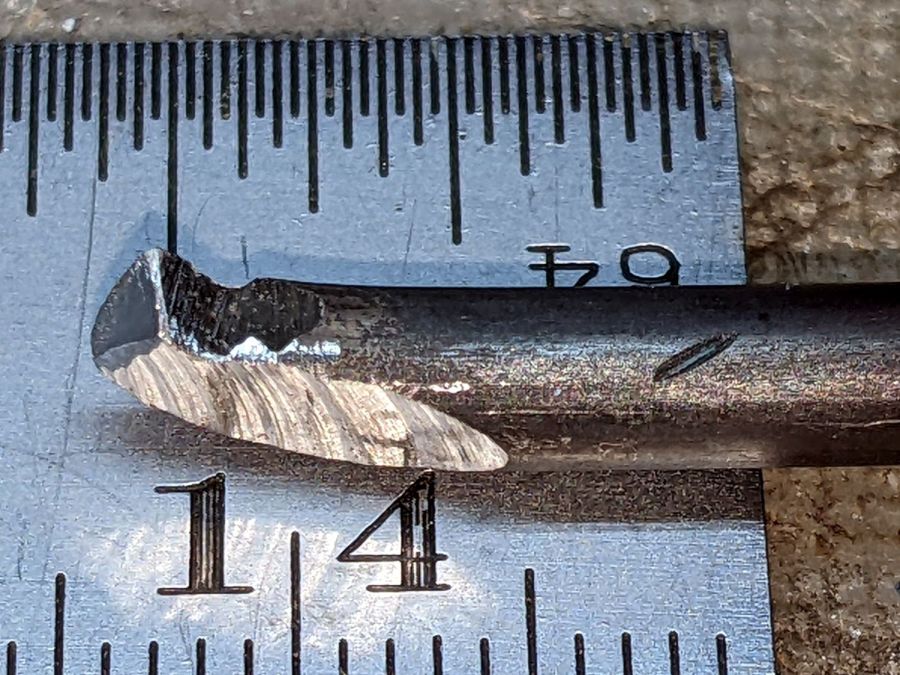
That’s maybe fifteen years of accumulated splotches.
I hope my refusal to buy their cartridges helped immanentize their eschaton, just a little.
Good riddance.