The Smell of Molten Projects in the Morning

Ed Nisley's Blog: Shop notes, electronics, firmware, machinery, 3D printing, laser cuttery, and curiosities. Contents: 100% human thinking, 0% AI slop.

Category: Home Ec

Things around the home & hearth

  • Whirlpool Clothes Dryer: Thermal Cutoff Trip

    Whirlpool Clothes Dryer: Thermal Cutoff Trip

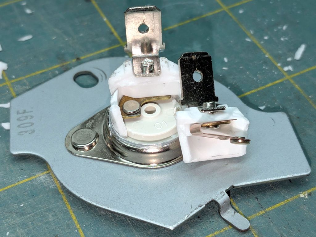
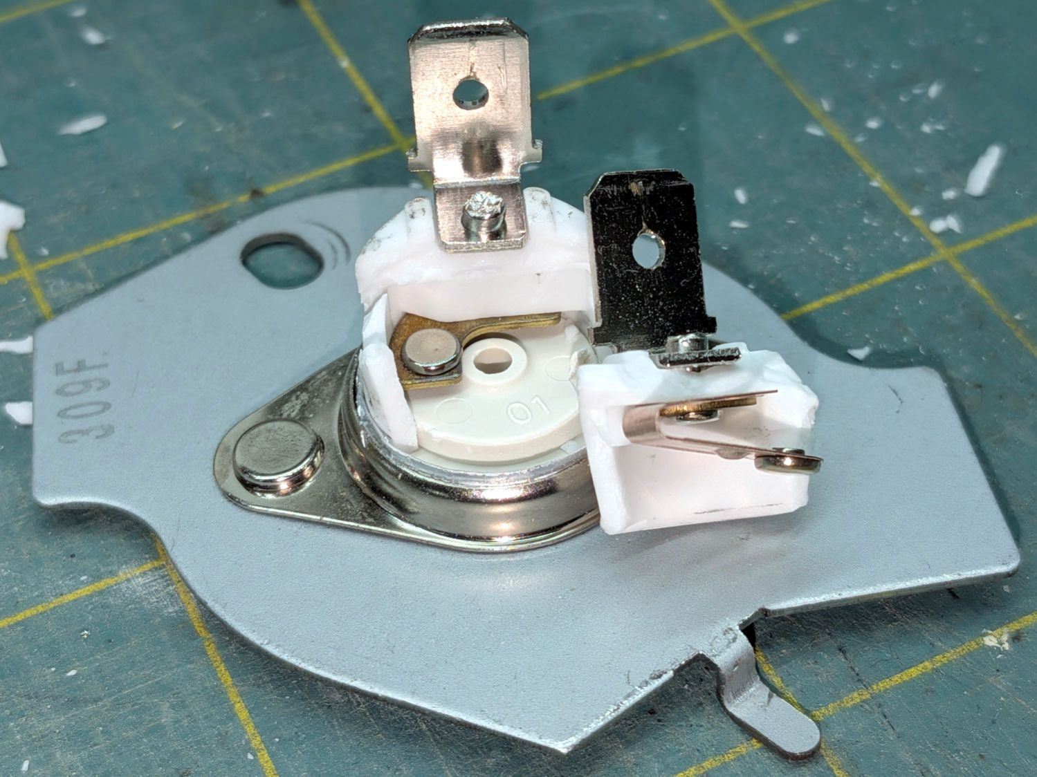
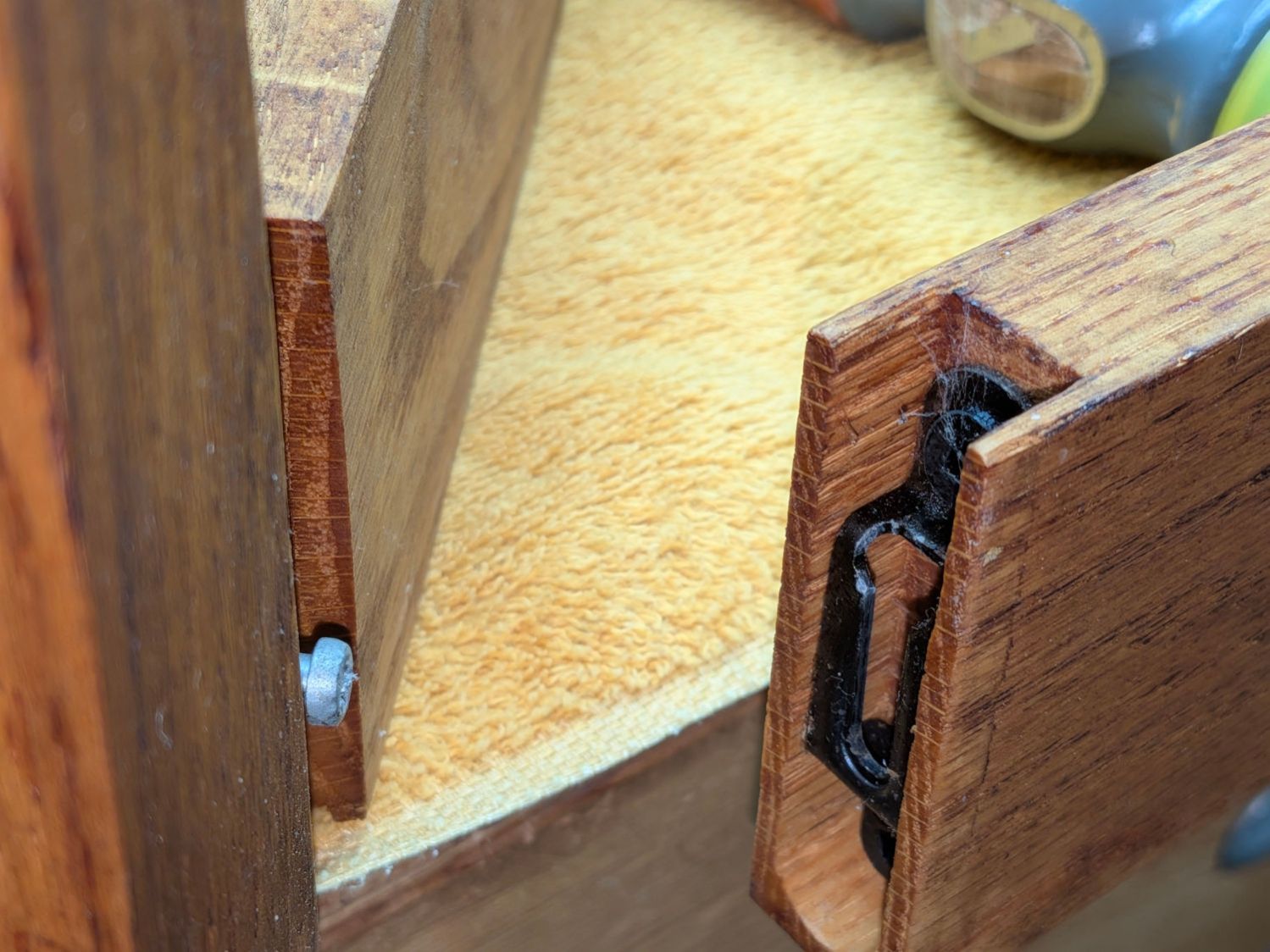
    A bit less than a year after replacing all the thermal switches / cutoffs / thermostats in the Whirlpool clothes dryer, the Thermal Cutoff went open-circuit. It’s located at the top of the heater duct:

    Whirlpool dryer - heater duct top
    Whirlpool dryer – heater duct top

    The wiring diagram lists it as tripping at 350 °F and “NOT RESETTABLE”:

    Whirlpool dryer - wiring diagram - detail
    Whirlpool dryer – wiring diagram – detail

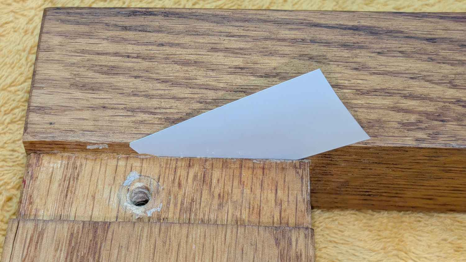
    Curiously, the replacement switch had only one mark:

    Whirlpool Clothes Dryer - thermal cutoff - marking
    Whirlpool Clothes Dryer – thermal cutoff – marking

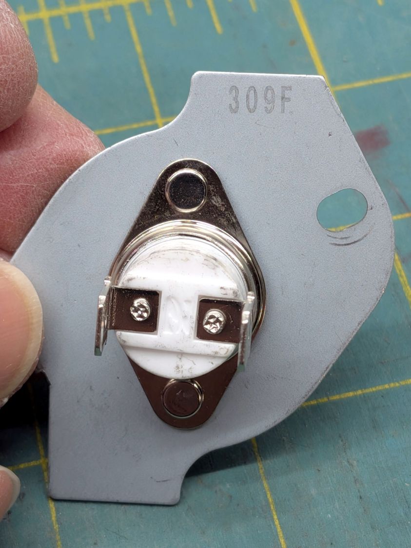
    I find it difficult to believe anybody would build a thermal cutout at 309°F = 154 °C.

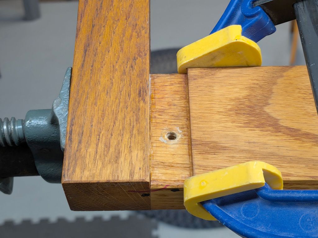
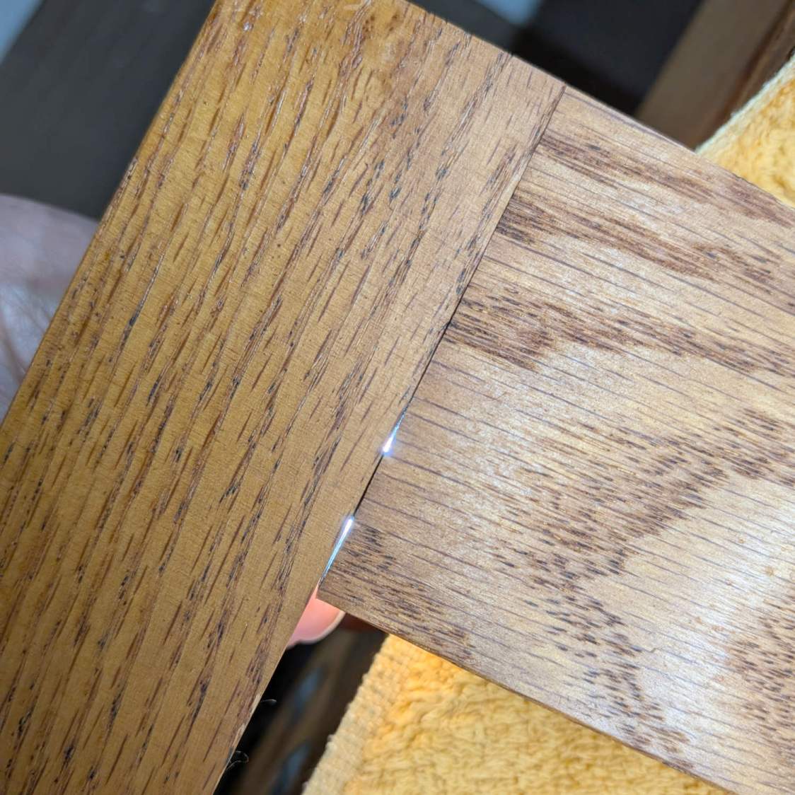
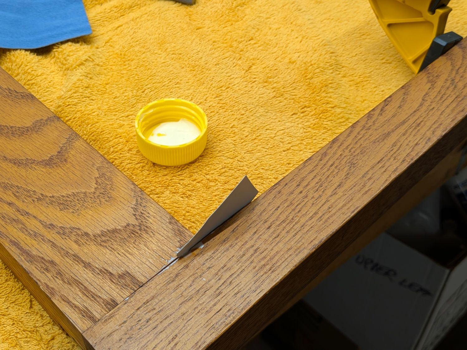
    Crushing it with a Vise-Grip reveals the interior:

    Whirlpool Clothes Dryer - thermal cutoff - disassembled
    Whirlpool Clothes Dryer – thermal cutoff – disassembled

    I don’t know what permanently opens the circuit in there, but it definitely happened. The contacts remain unblemished, so they were pressed firmly together until the end.

    With nothing to lose, I reinstalled the Thermal Cutoff I removed last year (*) and the dryer works fine again.

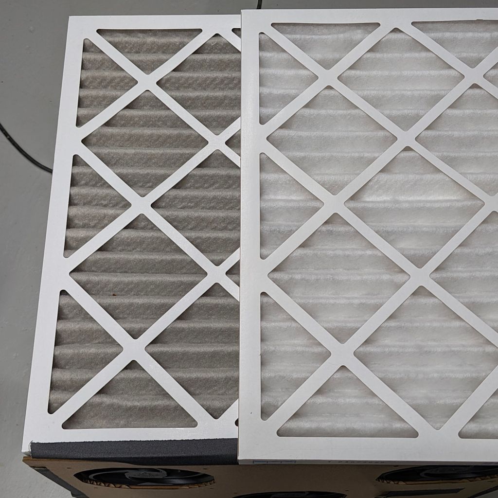
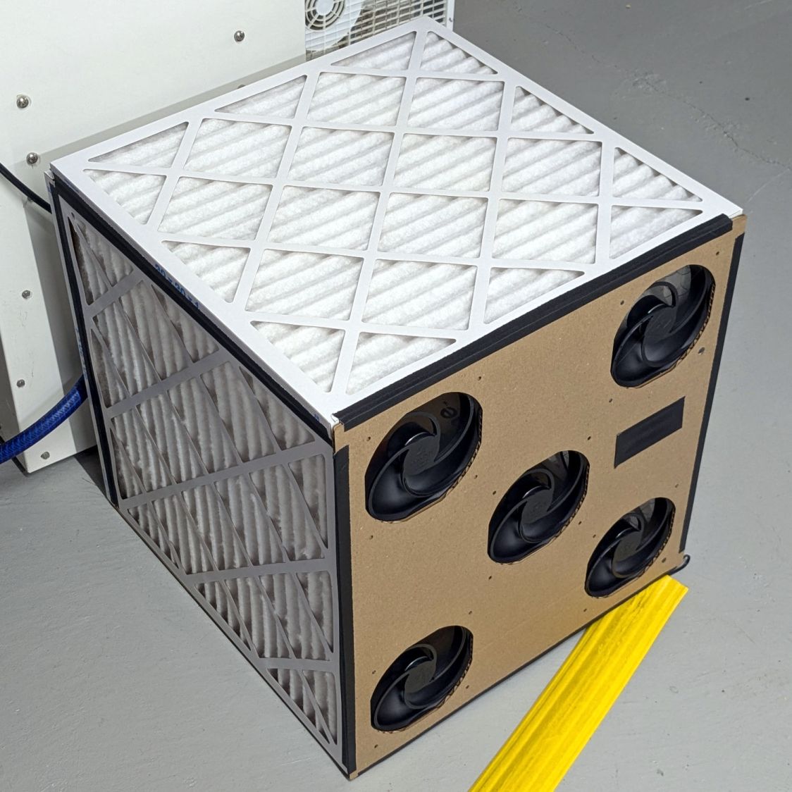
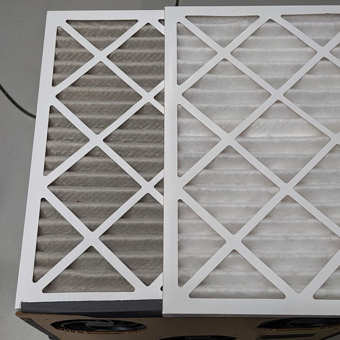
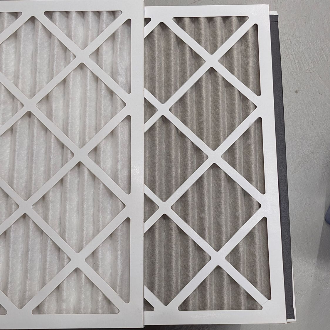
    It is possible lint accumulating in the filter bag I added to the exhaust vent restricted the airflow enough to overheat the cutoff, but the Operating Thermostat should keep the air around 155 °F and the Hi Limit thermostat should have tripped at 250 °F, long before the temperature reached 350°F.

    Another cutoff will arrive shortly and will remain in the Box o’ Dryer Parts against future need.

    (*) Which is why I keep the old parts around, because a dubious part on hand is much better than the new part I might not be able to get due to, oh, “supply chain issues”.

  • Oak Stool Leg Creak

    Oak Stool Leg Creak

    Our square oak stool developed an annoying creak in two of its legs, resulting in a teardown & glue-up.

    The legs come in pairs held in place by snug screw fittings:

    Oak Stool Legs - mechanical joint
    Oak Stool Legs – mechanical joint

    The screw on the left slides into the tapered fitting on the right and latches firmly in place: no creaks in there! I have no idea what that fitting is called; my search-fu is unavailing.

    In any event, the offending legs were loose enough to admit a 6 mil = 0.16 mm miniblind snippet shim:

    Oak Stool Legs - loose joint
    Oak Stool Legs – loose joint

    Our Young Engineer, having taken up woodworking as a serious hobby, suggested the joint might have a loose dowel, which will be difficult to fix. Peering into the gap with a flashlight below showed that was the case:

    Oak Stool Legs - dowel revealed
    Oak Stool Legs – dowel revealed

    While it might be possible to force the joint apart enough to properly re-glue the dowels, I opted for a half measure by applying a spreader and easing wood glue into the gaps using the shim:

    Oak Stool Legs - gluing
    Oak Stool Legs – gluing

    An overnight session with the pipe clamp eliminated the creak, at least for now:

    Oak Stool Legs - clamping
    Oak Stool Legs – clamping

    The blue-and-yellow clamp fixed the loose splinter you didn’t notice in the second picture.

    Traces of glue along inside the joints suggest I’d done something like in the deep past. Ideally, I’ve learned enough to get it right this time.

  • Steel Shelving Foot Pads

    Steel Shelving Foot Pads

    All of the plastic pads vanished from the legs of a steel shelf unit somewhere along the way:

    Steel Shelving Foot Pads - post shape
    Steel Shelving Foot Pads – post shape

    Some solid modeling produced a suitable replacement shape:

    Steel Shelving Foot Pads - no pegs - solid model
    Steel Shelving Foot Pads – no pegs – solid model

    A few prototypes (with a broken OEM version at lower left) matched the model to reality:

    Steel Shelving Foot Pads - test pieces
    Steel Shelving Foot Pads – test pieces

    They’re natural & black TPU, because the job requirements include being tough and bendy:

    Steel Shelving Foot Pads - installed
    Steel Shelving Foot Pads – installed

    Each one takes about half an hour to ooze from the Makergear M2, so after verifying the prototype’s fit, printing four at a time makes sense:

    Steel Shelving Foot Pads - slicer
    Steel Shelving Foot Pads – slicer

    The OpenSCAD code includes the pegs in the original and the first chunky TPU version:

    Steel Shelving Foot Pads - with pegs - solid model
    Steel Shelving Foot Pads – with pegs – solid model

    It turns out they don’t have any obvious benefit in a TPU pad, so they’re disabled in the code.

    Now those legs sit firmly on the floor and the post tops aren’t nearly so threatening.

    The OpenSCAD source code as a GitHub Gist:

    // Steel Shelf Foot Pads
    // Ed Nisley – KE4ZNU
    // 2026-04-18
    include <BOSL2/std.scad>
    /* [Hidden] */
    Protrusion = 0.01;
    NumSides = 4*9;
    $fn=NumSides;
    Clearance = 1.0/2;
    WallThick = 1.0 + Clearance;
    BaseThick = 2.0;
    PadOAH = BaseThick + 11.0;
    RollID = 6.4;
    RollOD = 7.4 + Clearance;
    RollOffset = 29.5;
    LegThick = 0.5 + 2*Clearance;
    Pins = [
    [-(RollOD/2), (RollOffset + RollOD/2),0],
    [(RollOffset + RollOD/2), -(RollOD/2),0],
    ];
    //—–
    // Build things
    union() {
    difference() {
    union() {
    for (pin = Pins)
    translate(pin)
    cyl(PadOAH,d=RollOD + 2*WallThick,anchor=BOTTOM);
    translate([-(WallThick + LegThick),-(WallThick + LegThick),0])
    cuboid([2*WallThick + LegThick,WallThick + LegThick + Pins[0].y,PadOAH],
    anchor=BOTTOM+LEFT+FRONT);
    translate([-(WallThick + LegThick),-(WallThick + LegThick),0])
    cuboid([WallThick + LegThick + Pins[1].x,2*WallThick + LegThick,PadOAH],
    anchor=BOTTOM+LEFT+FRONT);
    cyl(PadOAH,r=(WallThick + LegThick),anchor=BOTTOM);
    }
    up(BaseThick)
    cyl(PadOAH,r=LegThick,anchor=BOTTOM);
    up(BaseThick)
    for (pin = Pins)
    translate(pin)
    cyl(PadOAH,d=RollOD,anchor=BOTTOM);
    up(BaseThick) {
    translate(Pins[0])
    cuboid([RollOD/2,RollOD/2,PadOAH],anchor=BOTTOM+LEFT+BACK);
    translate(Pins[1])
    cuboid([RollOD/2,RollOD/2,PadOAH],anchor=BOTTOM+RIGHT+FRONT);
    }
    up(BaseThick) {
    fwd(LegThick)
    cuboid([LegThick,Pins[0].y + LegThick,PadOAH],anchor=BOTTOM+RIGHT+FRONT);
    left(LegThick)
    cuboid([Pins[1].x + LegThick,LegThick,PadOAH],anchor=BOTTOM+LEFT+BACK);
    }
    }
    if (false)
    for (pin = Pins)
    translate(pin) {
    cyl(PadOAH,d=RollID/2,anchor=BOTTOM);
    for (a = [0,90])
    zrot(a)
    cuboid([1.0,RollID – 2*Clearance,PadOAH],anchor=BOTTOM);
    }
    }

  • Basement Air Filter Box: Ewww!

    Basement Air Filter Box: Ewww!

    Late last year I assembled four air filters and a fan quintet into a box filter:

    Basement Air Filter Box - installed
    Basement Air Filter Box – installed

    Running continuously for three months made the air filters look like this (with an unused filter on top for comparison):

    Basement Air Filter Box - 3 months - A
    Basement Air Filter Box – 3 months – A

    I have not stretched the image contrast, so the new filter isn’t the pure white in the top picture, but it’s still about the same white as the cardboard frame. The floor is, indeed, painted gray.

    Looking at the pleats in the other direction to show I’m not making it up:

    Basement Air Filter Box - 3 months - B
    Basement Air Filter Box – 3 months – B

    The inside surface of the filters has the same gray appearance. The fans are, unsurprisingly, immaculate.

    Totally did not expect that!

    The filters sport a MERV 13 rating and snag “most smoke” from the passing air, so they’ve been collecting any fumes not sucked out of the laser cutter, along with whatever arises from other Basement Shop™ activities.

    So I’ll buy another set of filters, build another box, and see what accumulates during the next three months.

  • Auto Parking Light LED Bulbs: FAIL

    Auto Parking Light LED Bulbs: FAIL

    After about eight years and a similar failure last year, this came as no surprise:

    White W5W Parking Light - failed chips
    White W5W Parking Light – failed chips

    It’s a W5W “parking light” in the same fixture as the melty halogen high-beam bulbs (used as daytime running lights at half power), so it gets toasted on those occasions when we drive somewhere.

    The adhesive holding the LED strip to the aluminum shell fossilized and came loose:

    White W5W Parking Light - failed adhesive
    White W5W Parking Light – failed adhesive

    Now that I know what to look for, I’d get LED bulbs with chips soldered directly to the PCB, although it’s not obvious what holds the PCB to the aluminum frame.

    I reinstalled the original incandescent bulbs.

  • LED Garage Light: Desk Lamp Upcycling

    LED Garage Light: Desk Lamp Upcycling

    One of the heatsink panels from the defunct LED garage light now casts a uniform warm-white glow on my desk:

    LED Garage Light - desk light
    LED Garage Light – desk light

    A PCB intended as a lithium battery charger serves as a constant-current supply:

    LED Garage Light - constant current driver
    LED Garage Light – constant current driver

    The three trimpots, from left to right:

    • Constant-voltage limit adjustment
    • Full-charge current setpoint (irrelevant here)
    • Constant-current limit adjustment

    The as-received trimpot settings will be wildly inappropriate for a nominal 10 W COB LED array, so:

    • Connect the output to about 10 Ω of power resistors
    • … with an ammeter in series
    • Connect the input to a 12 VDC / 1-ish A wall wart
    • Adjust the output voltage to 10 V
    • Adjust the output current to 900 mA

    As long as the voltage limit is over about 10 V, it will (likely) never matter, as the LED forward drop doesn’t vary much with temperature. Setting it to something sensible keeps it out of the way.

    The middle trimpot apparently sets a voltage for a comparator to light an LED when the battery current drops below that level as it reaches full charge.

    Although the regulator touts its high efficiency, it does run hot and a heatsink seemed in order:

    LED Garage Light - heatsink
    LED Garage Light – heatsink

    Stipulated: the fins run the wrong way and it’s sitting in the updraft from the main heatsink. It’s Good Enough™.

    The switch on the top comes from the collection of flashlight tailcap switches and controls the 12 V input power. It’s buried up to its button in a generous dollop of JB Kwik epoxy, which seemed the least awful way to get that done.

    The solid model looks about like you’d expect:

    LED Lamp Driver case - switch housing - show solid model
    LED Lamp Driver case – switch housing – show solid model

    The OpenSCAD code exports the (transparent) lid as an SVG so I can import it into LightBurn and laser-cut some thin acrylic. Two tape snippets hold the lid in place pending more power-on hours, after which I’ll apply a few dots of cyanoacrylate adhesive and call it done.

    The case builds in two pieces that glue together to avoid absurd support structures:

    LED Lamp Driver case - switch housing - build solid model
    LED Lamp Driver case – switch housing – build solid model

    A 3D printed adapter goes between the desk lamp arm and the lamp heatsink bolt:

    LED Lamp Driver case - arm adapter - solid model
    LED Lamp Driver case – arm adapter – solid model

    The OpenSCAD source code files for the case and adapter arm as a GitHub Gist:

    // LED Lamp arm adapter
    // Ed Nisley – KE4ZNU
    // 2026-03-18
    include <BOSL2/std.scad>
    Layout = "Adapter"; // [Show,Build,ArmClamp,SinkClamp,Adapter]
    /* [Hidden] */
    HoleWindage = 0.2;
    Protrusion = 0.01;
    Gap = 5.0;
    $fn=5*3*4;
    HoleOC = 45.0;
    ArmRad = 7.5;
    ArmWidth = 11.3;
    SinkOD = 11.5;
    SinkThick = 3.2;
    SinkOC = 20.0;
    ClampThick = 5.0; // outside sink, watch thinning due to hull()
    // Define things
    // Screw & bushings in lamp arm bracket
    // … over-long bushings to prevent coincident surfaces
    module ArmClamp() {
    BushingThick = 1.5;
    BushingOD = 9.0;
    union() {
    ycyl(ArmWidth,d=4.0 + HoleWindage); // central M4 screw
    for (j=[-1,1]) {
    back(j*(ArmWidth – BushingThick + Protrusion)/2)
    ycyl(BushingThick + Protrusion,d=BushingOD);
    back(j*(ArmWidth + 10)/2)
    cuboid([2*ArmRad,10,2*ArmRad]);
    }
    }
    }
    module SinkClamp() {
    union() {
    ycyl(2*SinkOC,d=6.0 + HoleWindage); // central M6 screw
    for (j=[-1,1])
    back(j*SinkOC/2) {
    ycyl(SinkThick + Protrusion,d=SinkOD);
    cuboid([SinkOD,SinkThick + Protrusion,2*SinkOD]);
    }
    }
    }
    module Adapter() {
    difference() {
    hull() {
    right(HoleOC)
    ycyl(ArmWidth,r=ArmRad);
    ycyl(SinkOC + SinkThick + 2*ClampThick,d=SinkOD);
    }
    right(HoleOC)
    ArmClamp();
    SinkClamp();
    }
    }
    // Build it
    if (Layout == "ArmClamp")
    ArmClamp();
    if (Layout == "SinkClamp")
    SinkClamp();
    if (Layout == "Adapter")
    Adapter();
    if (Layout == "Build")
    up(SinkOD/2)
    yrot(-atan((ArmRad – SinkOD/2)/HoleOC))
    Adapter();
    // LED Constant-current driver case
    // Ed Nisley – KE4ZNU
    // 2026-03-15
    include <BOSL2/std.scad>
    Layout = "Show"; // [Show,Build,Case,Lid,LidSVG,Switch]
    /* [Hidden] */
    ThreadThick = 0.2;
    HoleWindage = 0.2;
    Protrusion = 0.01;
    Gap = 5.0;
    WallThick = 1.8;
    TapeThick = 1.5;
    DriverOA = [48.5,13.5 + TapeThick,23.5]; // PCB forward Y, pots along top to rear
    SinkOA = [31.5,12.0,15.5]; // fins forward
    SinkOffset = [(DriverOA.x – SinkOA.x)/2,0,2.0]; // from lower left front corner of PCB
    AdjPots = [14,24,34]; // screwdriver adjust offsets
    AdjOD = 3.0; // … access hole dia
    CaseOA = DriverOA + [2*WallThick,2*WallThick,2*WallThick];
    echo(CaseOA=CaseOA);
    LidOA = [CaseOA.x – WallThick,CaseOA.z – WallThick,1.0];
    Cables = [8.0,3.0 + WallThick/2,LidOA.z];
    SwitchWireOC = DriverOA.x – 6.0;
    SwitchCapBase = [DriverOA.x + WallThick,DriverOA.y + WallThick];
    SwitchCapTop = [DriverOA.x,12.0];
    SwitchCavity = [25.0,10.5,5.5];
    // Define things
    module Lid() {
    difference() {
    cuboid(LidOA,anchor=BOTTOM+FWD+LEFT);
    for (i = AdjPots)
    translate([i,LidOA.y – AdjOD/2 – WallThick/2,-Protrusion])
    cyl(LidOA.z + 2*Protrusion,d=AdjOD,anchor=BOTTOM,$fn=8,spin=180/8);
    translate([LidOA.x/2,-Protrusion,-Protrusion])
    cuboid(Cables + [0,Protrusion,2*Protrusion],rounding=1.0,edges=[BACK+LEFT,BACK+RIGHT],anchor=BOTTOM+FWD);
    }
    }
    module SwitchBox() {
    difference() {
    prismoid(SwitchCapBase,SwitchCapTop,SwitchCavity.z,anchor=BOTTOM);
    down(Protrusion)
    cuboid(SwitchCavity + [0,0,2*Protrusion],anchor=BOTTOM);
    hull()
    for (i=[-1,1])
    right(i*SwitchWireOC/2)
    zcyl(CaseOA.z,d=3.0,$fn=8,spin=180/8);
    }
    }
    module Case() {
    difference() {
    cuboid(CaseOA,chamfer=WallThick/2,anchor=BOTTOM+FWD+LEFT);
    translate([WallThick,WallThick + Protrusion,WallThick])
    cuboid(DriverOA + [0,WallThick + Protrusion,0],anchor=BOTTOM+FWD+LEFT);
    translate(SinkOffset + [WallThick,WallThick + 2*Protrusion,WallThick])
    cuboid(SinkOA,anchor=BOTTOM+BACK+LEFT);
    for (i=[-1,1])
    translate([i*SwitchWireOC/2 + CaseOA.x/2,CaseOA.y/2,CaseOA.z/2])
    zcyl(CaseOA.z,d=2.0,anchor=BOTTOM,$fn=8,spin=180/8);
    translate([WallThick/2,(CaseOA.y + LidOA.z),WallThick/2])
    xrot(90)
    scale([1,1,2])
    Lid();
    }
    }
    // Build it
    if (Layout == "Switch")
    SwitchBox();
    if (Layout == "Case")
    Case();
    if (Layout == "Lid")
    Lid();
    if (Layout == "LidSVG")
    projection(cut=true)
    Lid();
    if (Layout == "Show") {
    Case();
    translate(SinkOffset + [WallThick,WallThick + 2*Protrusion,WallThick])
    color("Gray",0.7)
    cuboid(SinkOA,anchor=BOTTOM+BACK+LEFT);
    translate([CaseOA.x/2,CaseOA.y/2,CaseOA.z])
    SwitchBox();
    translate([WallThick/2,CaseOA.y,WallThick/2])
    xrot(90)
    color("Gray",0.7)
    Lid();
    }
    if (Layout == "Build") {
    fwd(Gap)
    xrot(90)
    Case();
    translate([CaseOA.x/2,(Gap + CaseOA.y/2),0])
    SwitchBox();
    }
  • Custom 45° Triangle Quilting Ruler

    Custom 45° Triangle Quilting Ruler

    Mary’s current quilt project has a corner design with an essentially infinite number of 45° triangles, which another custom ruler will simplify:

    45° Quilting Ruler - finished
    45° Quilting Ruler – finished

    That’s the end result of several iterations, proceeding from doodles to sketches to increasingly accurate laser-cut prototypes:

    45° Quilting Ruler - prototypes
    45° Quilting Ruler – prototypes

    A “ruler” in quilting parlance is a thing guiding the sewing machine’s “ruler foot” across the fabric (or, for sit-down machines, the fabric under the foot) in specific directions:

    45° Quilting Ruler - in use
    45° Quilting Ruler – in use

    That’s a practice quilt on scrap fabric: quilters need prototypes, too!

    The foot is 0.5 inch OD, within a reasonable tolerance, which accounts for the slot width in the ruler. It’s also intended to run against 1/4 inch thick rulers, which accounts for the thickness of that slab of acrylic.

    The engraved lines & arcs are on the bottom of the ruler to eliminate parallax errors against the fabric, so the bottom is upward and the text is mirrored for the laser:

    45° Quilting Ruler - cutting
    45° Quilting Ruler – cutting

    Although fluorescent green acrylic may have higher visibility, clear seems adequate for the fabric in question:

    45° Quilting Ruler - colored fabric
    45° Quilting Ruler – colored fabric

    I very carefully trimmed the arcs against the ruler outline using LightBurn’s Cut Shapes, which turned out to be a Bad Idea™, because the high-current pulse as the laser fires causes a visible puncture wound at the still-to-be-cut edge:

    45° Quilting Ruler - edge damage
    45° Quilting Ruler – edge damage

    Those are not straight lines and the plastic isn’t bent!

    A closer look:

    45° Quilting Ruler - edge damage - detail
    45° Quilting Ruler – edge damage – detail

    The arcs without wounds started from their other end and stopped at the edge, which is perfectly fine.

    The wounds are unsightly, not structural, but the next time around I’ll extend the markings a millimeter beyond the edges into the scrap material.

    The overall design looks busier than it is, because I put different features on different layers in case they needed different settings:

    45 Degree Quilting Ruler - LightBurn layout
    45 Degree Quilting Ruler – LightBurn layout

    The LightBurn SVG layout as a GitHub Gist:

    Loading
    Sorry, something went wrong. Reload?
    Sorry, we cannot display this file.
    Sorry, this file is invalid so it cannot be displayed.