For a square patio table (with one missing foot), of course:
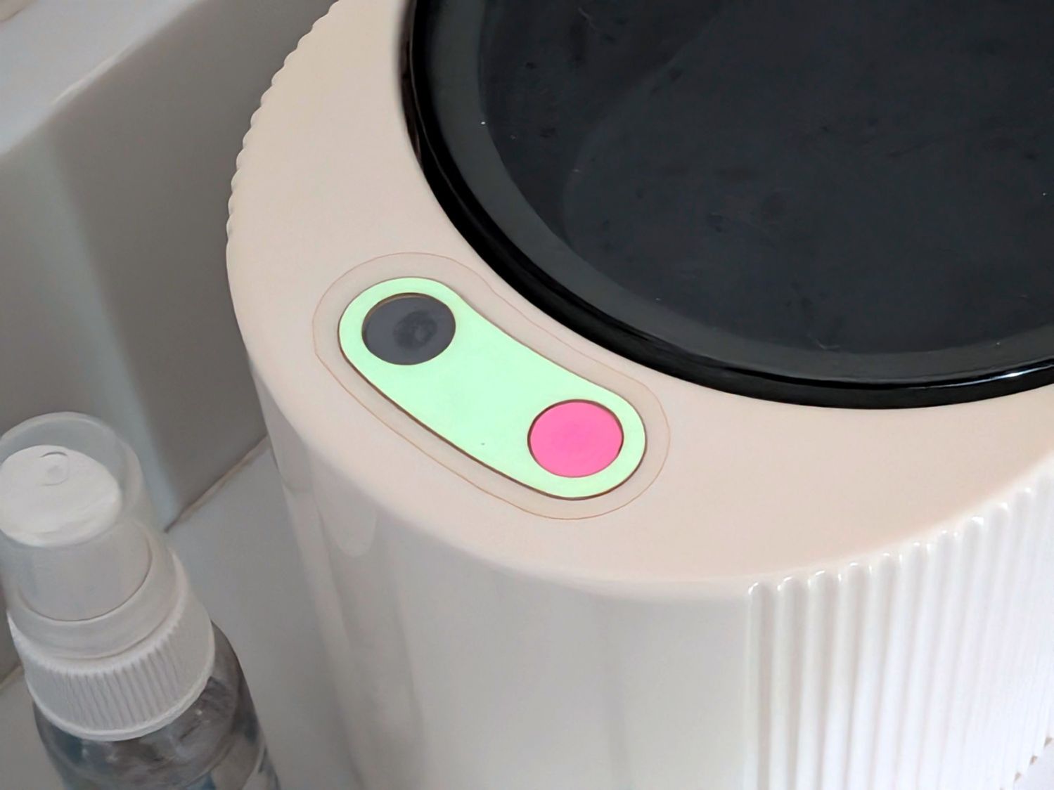
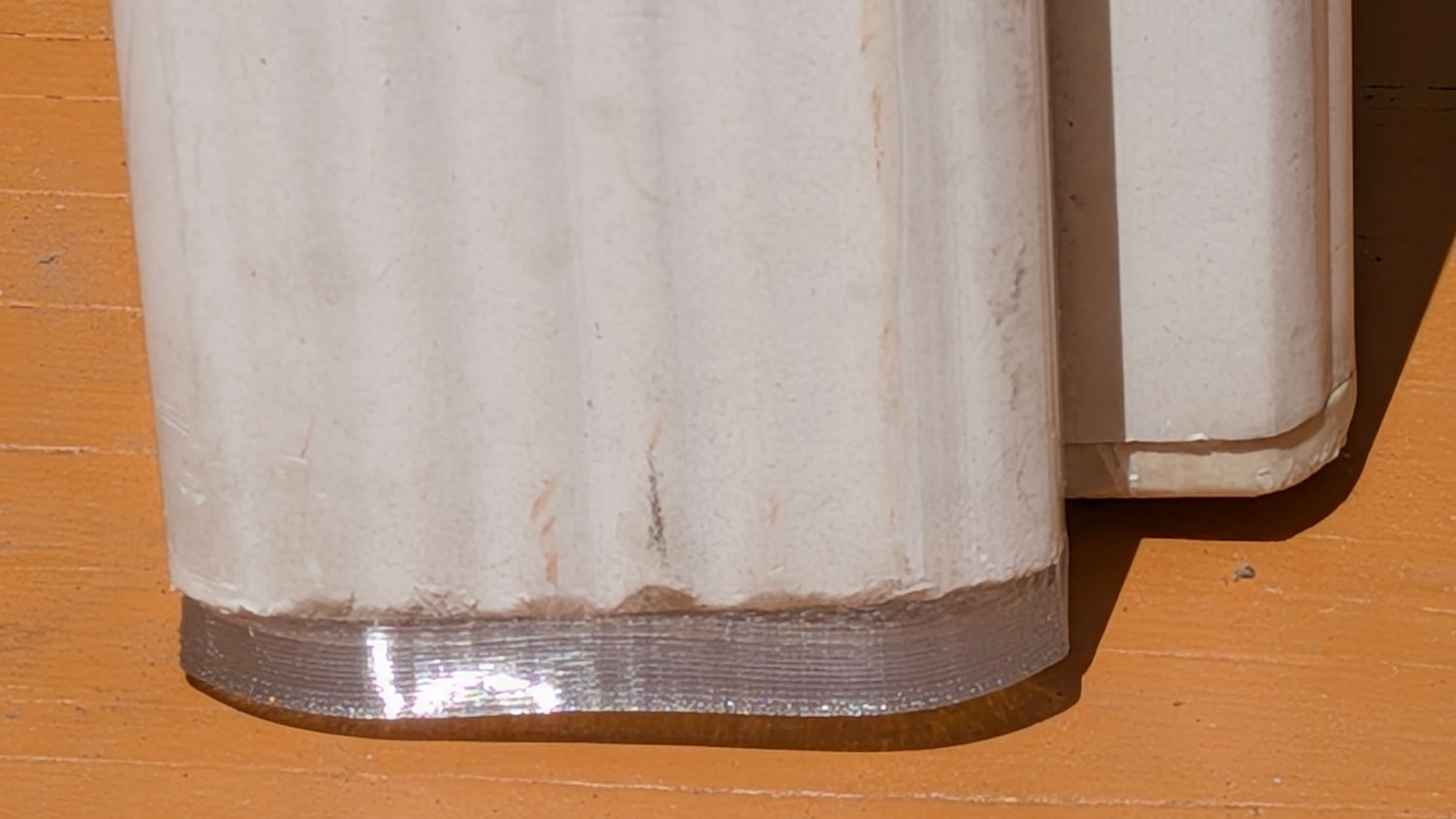
These are chunky enough to demonstrate they’re made of clear-ish TPU, at least when backlit:
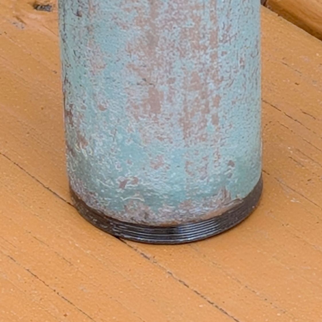
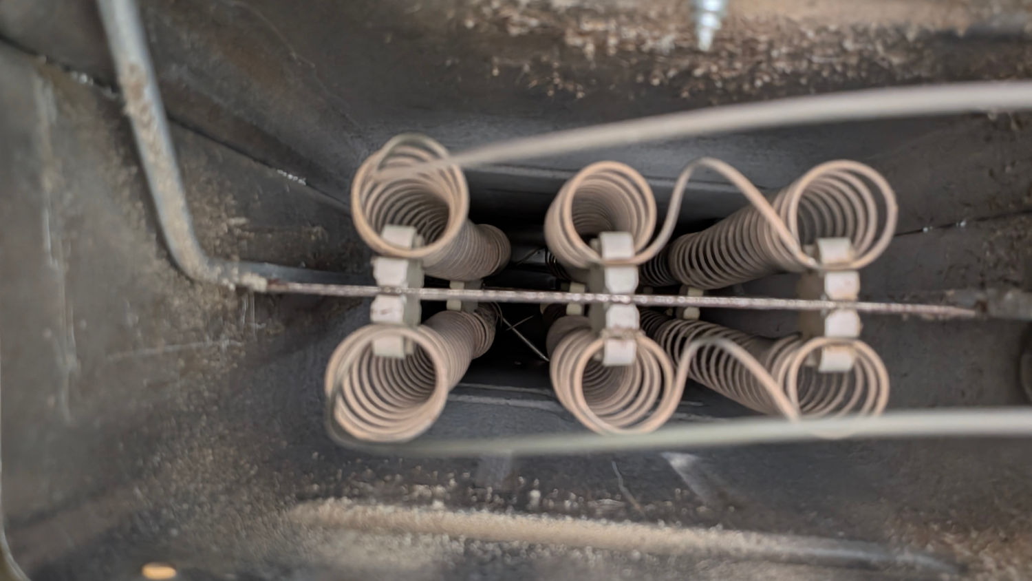
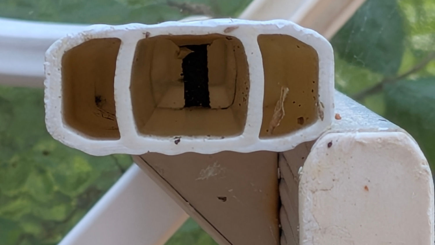
The interior of the leg determines what fits into it:
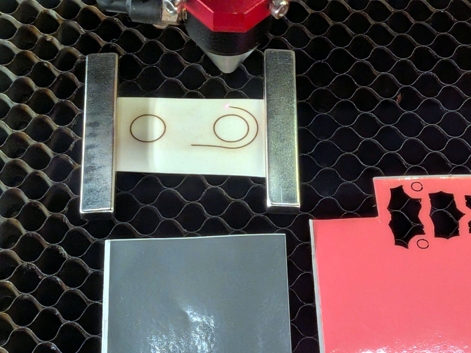
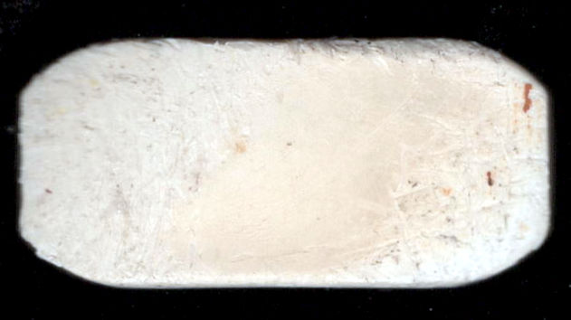
I pried out another foot, scanned it, and blew out the contrast:
Importing that into LightBurn let me draw a rectangle matching the measured size, then node-edit the corners to approximate the shape:
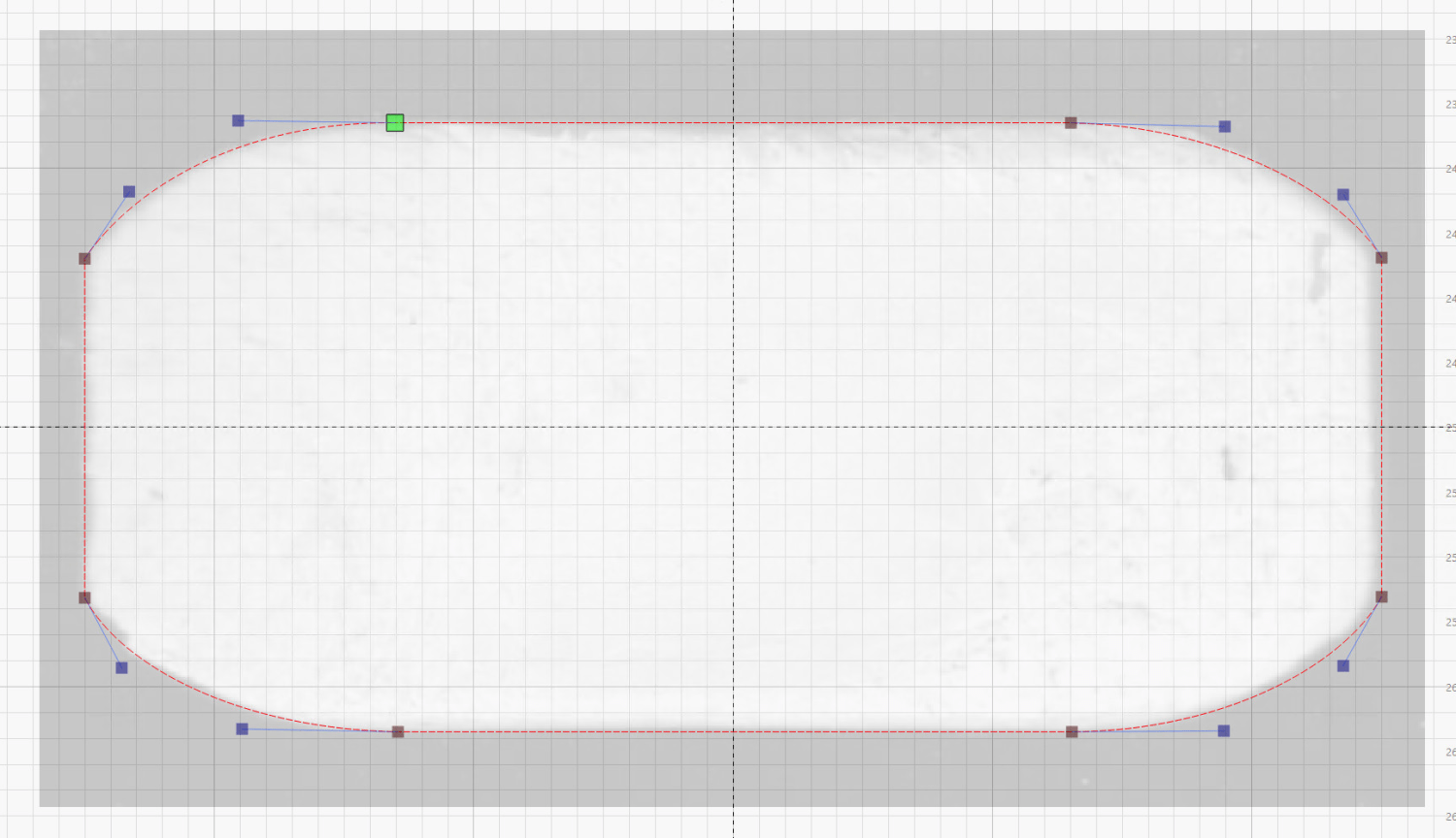
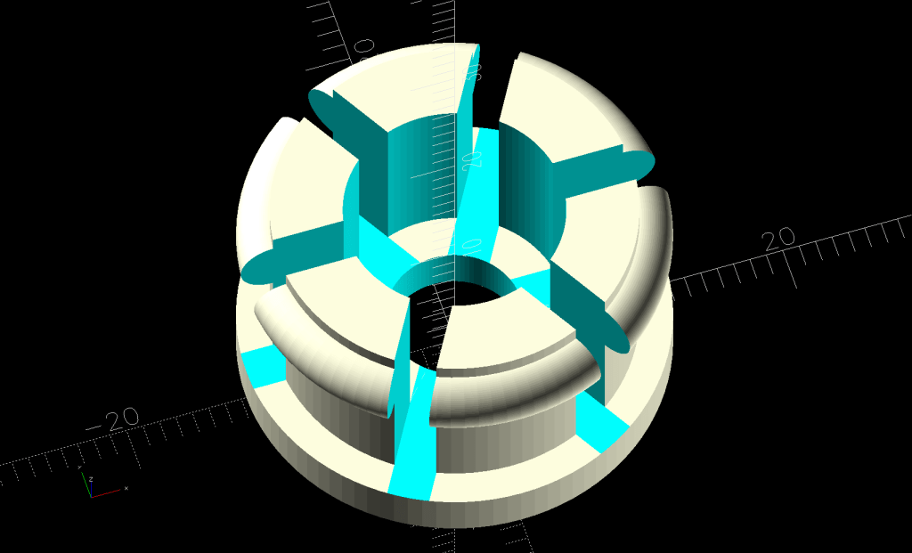
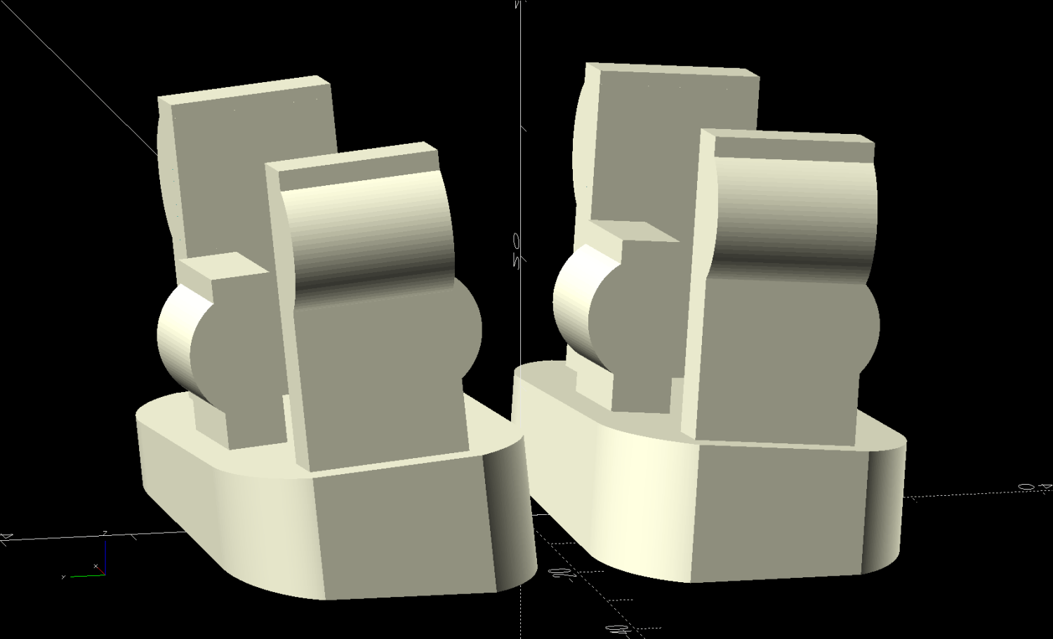
Export that shape as an SVG, import into OpenSCAD, and turn it into a solid model:
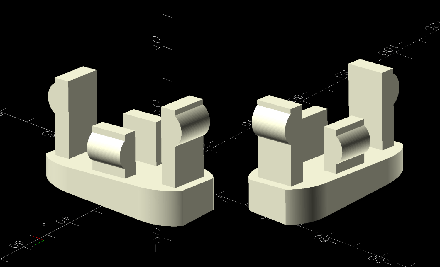
That’s the Show view simulating the actual positions, which demonstrates why the pair of legs at each corner wear mirror-imaged feet. The Build view arranges the pair more sensibly for 3D printing:
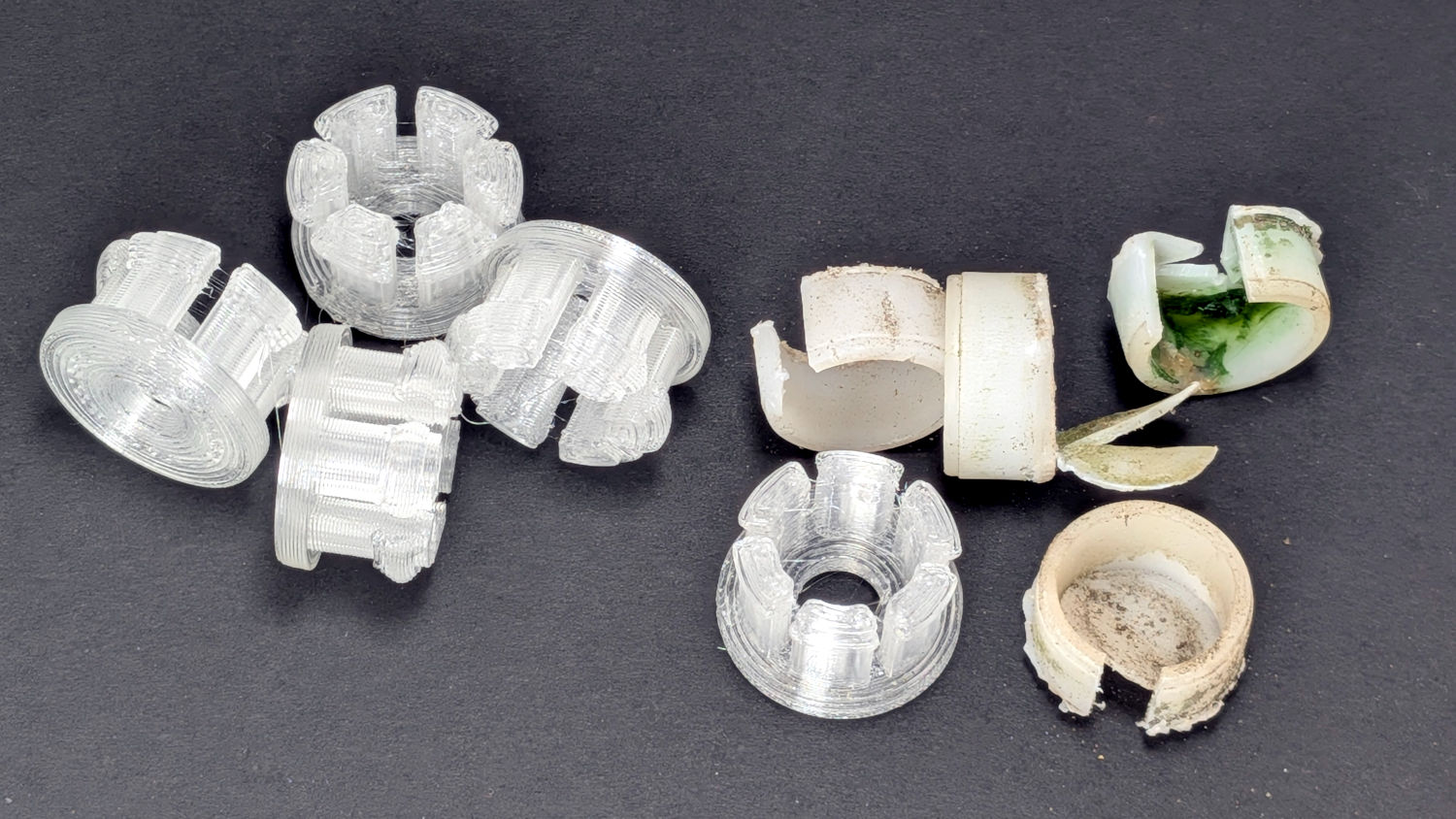
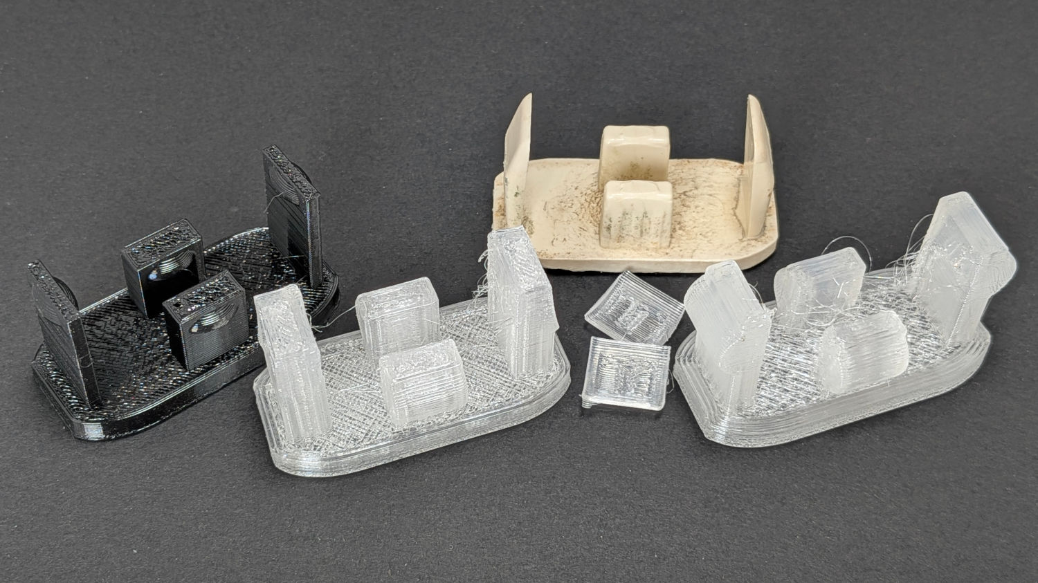
The protrusions and their bumps went through several iterations on the way to being functional, with the black TPU prototype on the left being entirely too bendy and the first clear version requiring utility knife editing to fit the end posts inside the leg:
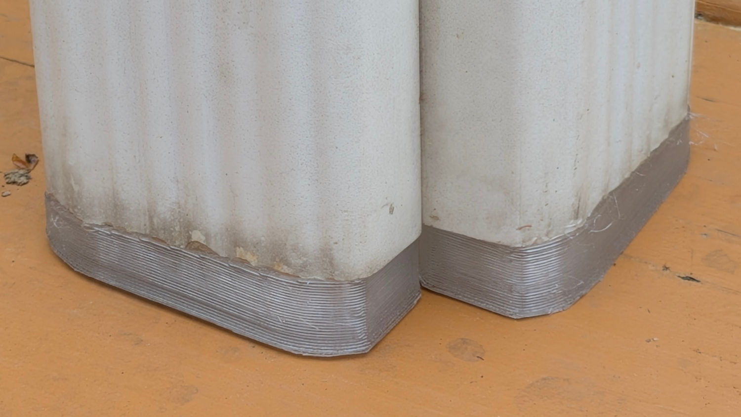
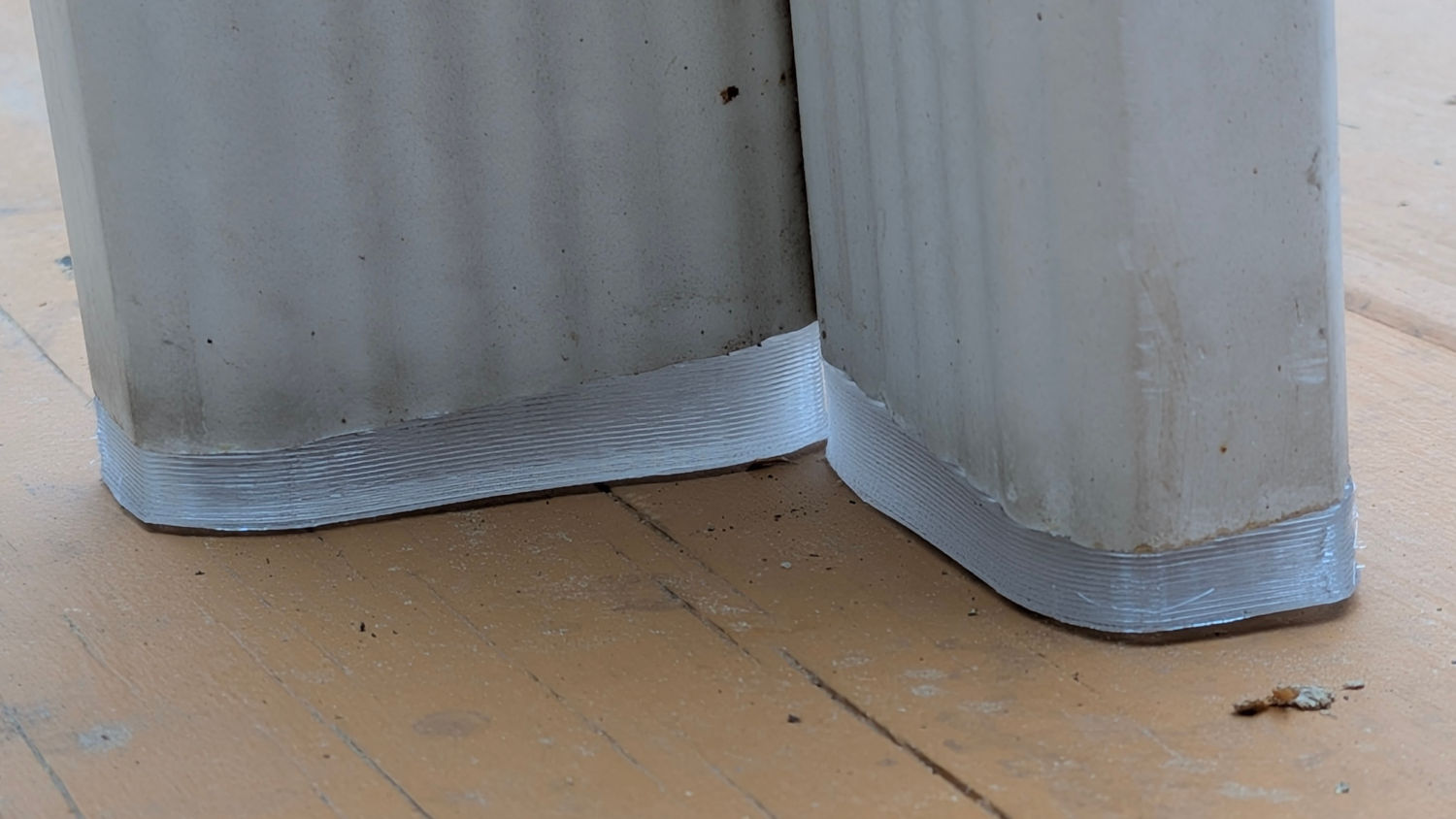
The original feet seem to be injection-molded ABS with a flat bottom intended to erode one corner against whatever the table stands on. However, the legs splay out at 5° from the vertical, which makes the flat bottom I used for the first few iterations obviously wrong:
Somebody who can math harder than I would resolve the two angles and all the measurements into a single transformation matrix, but I rotated the foot separately around the X and Y axes, trigged the lowest corner to the proper height, then chopped off everything below Z=0. Works for me.
The OpenSCAD source code as a GitHub Gist:
| // Patio Table Foot – rectangular legs | |
| // Ed Nisley – KE4ZNU | |
| // 2026-05-26 | |
| include <BOSL2/std.scad> | |
| Layout = "Show"; // [Show,Build] | |
| /* [Hidden] */ | |
| HoleWindage = 0.2; | |
| Protrusion = 0.01; | |
| NumSides = 4*3*2*4; | |
| Gap = 5.0/2; | |
| $fn=NumSides; | |
| PadOA = [50,23.5,4.5]; | |
| LegAngles = [5,5]; | |
| EndStrut = [2.5 + 2.5,13.3 – 1.0,23.0]; | |
| SideStrut = [12.0,5.5 – 1.0,13.0]; | |
| Clearance = 0.5; | |
| StrutsOC = [44.0 – EndStrut.x,18.0 – SideStrut.y]; | |
| //—– | |
| // Define it | |
| module Foot(angles = LegAngles) { | |
| difference() { | |
| up((PadOA.x/2)*abs(sin(angles.x)) + (PadOA.y/2)*abs(sin(angles.y))) | |
| xrot(angles.x) yrot(angles.y) | |
| union() { | |
| down(3*PadOA.z) | |
| linear_extrude(4*PadOA.z) | |
| left(PadOA.x/2) fwd(PadOA.y/2) | |
| import("Patio Table Foot – pad outline.svg",center=true); | |
| up(PadOA.z) | |
| for (i = [-1,1]) | |
| right(i*StrutsOC.x/2) | |
| cuboid(EndStrut,anchor=BOTTOM) position(TOP) | |
| down(EndStrut.y/2) left(i*Clearance) | |
| pie_slice(r=(PadOA.x – StrutsOC.x)/2,ang=180,l=EndStrut.y,anchor=CENTER,spin=-i*90,orient=FRONT); | |
| up(PadOA.z) | |
| for (j = [-1,1]) | |
| fwd(j*StrutsOC.y/2) | |
| cuboid(SideStrut,anchor=BOTTOM) position(TOP) | |
| down(SideStrut.x/2) zrot(90) right(j*Clearance) | |
| pie_slice(r=(PadOA.y – StrutsOC.y)/2,ang=180,l=SideStrut.x,anchor=CENTER,spin=j*90,orient=FRONT); | |
| } | |
| cuboid(4*PadOA,anchor=TOP); | |
| } | |
| } | |
| //—– | |
| // Build it | |
| if (Layout == "Show") { | |
| back(PadOA.y/2 + Gap) | |
| Foot(); | |
| left(0.8*PadOA.x) fwd(PadOA.y) zrot(-90) | |
| yflip() Foot(); | |
| } | |
| if (Layout == "Build") { | |
| union() { | |
| fwd(PadOA.y/2 + Gap) | |
| Foot(); | |
| back(PadOA.y/2 + Gap) | |
| yflip() Foot(); | |
| } | |
| } |