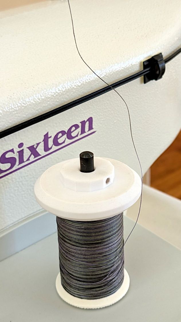
Mary wanted a Ruler Foot (a.k.a. Handi Feet Sure Foot) on her Handi Quilter HQ Sixteen sewing machine, which required removing the original foot, installing the Handi Feet Conversion Kit, then adjusting the foot height above the needle plate:
The Conversion Kit instructions repeatedly recommend hauling the machine to your local Handi Quilter authorized dealer / repair center, which would be an hour’s drive away. Suffice it to say I’m both authorized by a suitable authority and a dab hand with a hex wrench: I can do this thing.
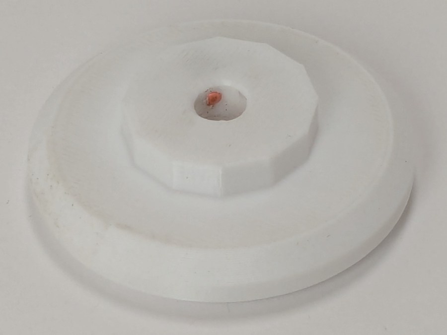
The original foot is a welded assembly with an M5×0.8 screw thread matching the leftmost (darker) rod on the machine:
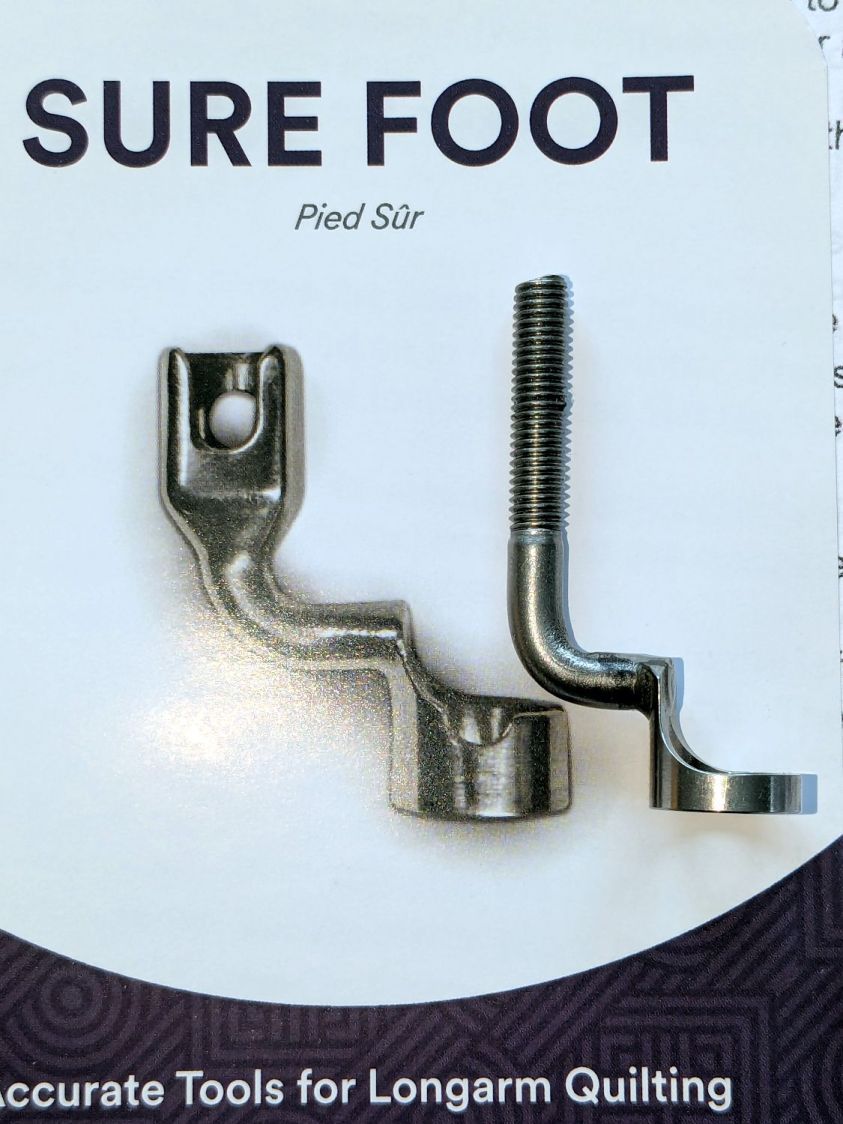
It’s sitting atop the label of the Sure Foot kit with a picture of the ruler foot.
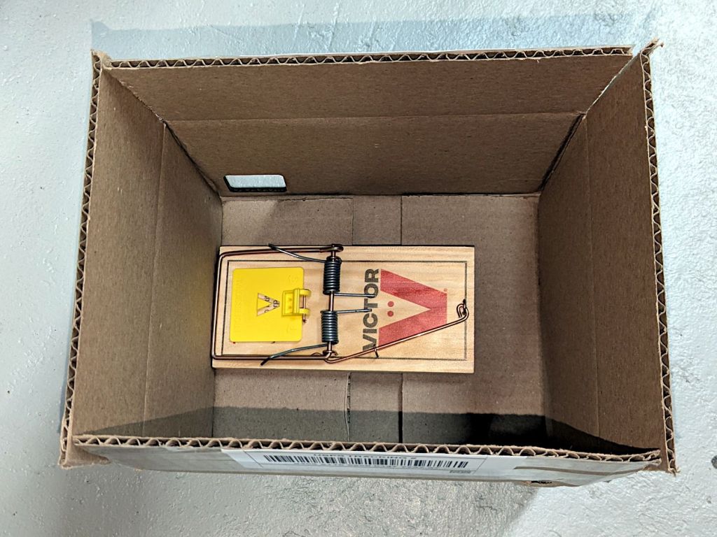
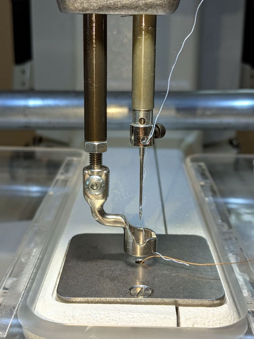
Although the instructions suggest you can install the conversion kit without removing the machine cover, I wanted to see what was going on in there and verify everything fit properly:
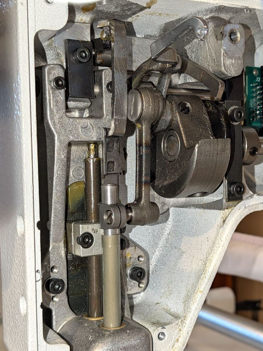
As above, the foot / adapter screws into the left rod, with the rectangular aluminum clamp attached to the follower riding the cam near the top of the machine. The rod slides on the greasy pin absorbing the torque from the follower.
I had to loosen the clamp, slide the rod upward, unscrew the original foot, install the adapter, adjust the rod position for the proper 0.5 mm spacing between ruler foot and the needle plate at bottom dead center, then tighten the screw. The disturbed grease above the block reveals I moved the rod upward about 8 mm through that block during the process; it now sits lower, just a few millimeters above where the factory tech assembled it for the original foot.
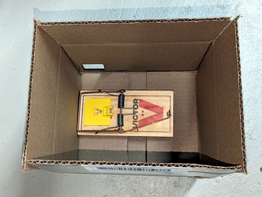
The top photo shows half a dozen threads between the top of the adapter and the bottom of the jam nut. Without adjusting the rod position in the clamp, the adapter screw threads are the only way to adjust the foot-to-plate space: each full turn moves the foot 0.8 mm. I screwed the adapter completely into the rod, then backed it out three turns to leave enough adjustment for other feet and fabrics.
The machine cover has a hole providing access to the clamp screw, so, in principle, you can stick a hex wrench in there to loosen / tighten the clamp while making fine adjustments in the foot position, all without removing the cover. If one full turn of the adapter doesn’t set the right position, I highly recommend removing the machine cover to see what you’re doing.
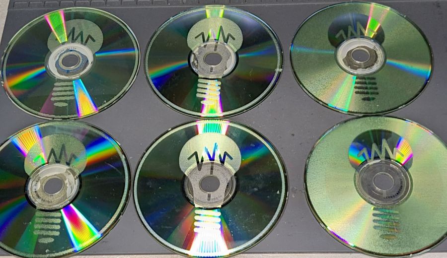
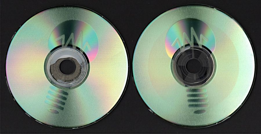
We then installed the Ruler Base on the machine, which required removing the preinstalled Medium fuzzy spacer strips, and all’s well that ends well.