Ed Nisley's Blog: Shop notes, electronics, firmware, machinery, 3D printing, laser cuttery, and curiosities. Contents: 100% human thinking, 0% AI slop.
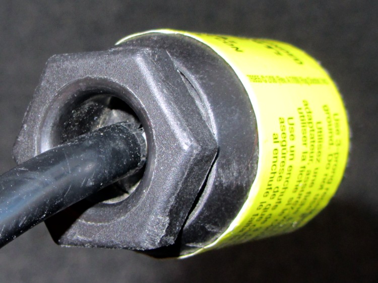
Driven by forces beyond my control, I had to rent a carpet cleaner from a local Big Box home repair store. The rugged line cord plug had an unusual (to me, anyway) strain relief fitting on the back, consisting of a circumferential clamp around the cord and a large diameter, deeply recessed opening on the nut to prevent the cord from flexing sharply:
AC Line Cord Plug – clamp nut
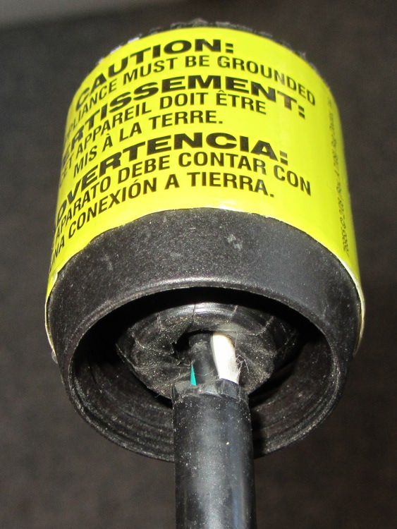
But something seemed odd, so I unscrewed the finger-tight clamping nut:
AC Line Cord Plug – clamp fingers
Whoever installed the cord cut the insulation back far too much, as those fingers should close on the insulation jacket, not the conductors.
I fought down my instinctive response, took a deep breath, clicked my heels together three times, repeated “This is not my problem”, and suddenly it wasn’t my problem any more. I tried reporting it to the harried clerk at the Big Box Store, but she instantly fluttered off to help somebody else after noting my return in the Big Book of Rental Contracts.
The hard-floor brush for our old Samsung VAC-9048R vacuum cleaner began scratching the hardwood floor, which called for some investigation & repair. The Fine Manual doesn’t even mention the hard floor brush, so it’s obvious I’m on my own (as is usually the case). Believe it or not, we actually discussed buying a vacuum cleaner, but the new ones have poor reviews, bulky & awkward plastic widgets on the handle, or suffer from other glaringly obvious faults; although this one is aging poorly, it’s at least workable. Plus, I bought a lifetime supply of bags when it was new and it’s not dead yet.
So, we begin…
The rollers that used to support the front of the brush have worn down, allowing the bottom cover to erode on the floor. The right side ran through something sticky in the recent past:
Samsung 9048 – worn roller – right
The left side may not be sticky, but it’s in no better shape:
Samsung 9048 – worn roller – left
Remove the two obvious screws, pry the front edge up, and the whole cover plate pops off to reveal the two rollers. They pull straight out of the shaft support brackets molded into the top frame. Even their metal shafts show grievous wear:
Samsung 9048 – worn roller parts
The rollers consist of a hard plastic hub supporting a flexible rubbery tire, turning on a 3 mm steel shaft that’s worn on one side (which was downward, of course). The central holes in the rollers probably used to fit the shafts, but they’re now worn to 4 mm ID. The tires were probably a lot larger in diameter, too, back when they were new.
A bit of rummaging in the Basement Laboratory Warehouse Wing produced a bag of vibration isolation bushings that had about the right consistency to become tires:
Samsung 9048 – rollers and surplus vibration isolation bushings
They’re much larger than necessary, but are now, shall we say, fully depreciated and ready for a new, if somewhat downsized, lifestyle.
Unfortunately, they don’t fit onto the existing hubs, so I can’t use the hubs as a template. Fortunately, I have a lathe and some random nylon stock (with crosswise notches that didn’t pose much of a problem):
Samsun 9048 – turning roller hub
I came to my senses before converting this into a 3D printer project. If I had to make more than two hubs, it’d be a good idea to solid-model and print them, even if they’re just barely large enough to allow solid infill:
Samsun 9048 – finished roller hub
I’d go for a 3 mm ID to increase the wall width; these have a 4 mm ID to fit the brass bushings described below. There’s no significant overhang and they’d print with no problems. Maybe next time?
The isolation bushings cut easily with a sharp razor knife, so I pared them down to a bit over what I estimated to be the finished roller OD and width:
Samsung 9048 – roller tire before grinding
The 10-32 screw in that shiny new hub serves as an arbor in the lathe, where I held a Dremel tool with a sanding drum down on the compound rest, ran the lathe at its slowest back-gear speed, and sanded the bushing down to what seemed to be the right OD for the tire:
Samsung 9048 – grinding roller tire
The white snout in front leads to a shopvac that caught most of the dust. The front of the lathe chuck shows it wasn’t perfectly effective and I should have worn a dust mask; my glasses didn’t collect much dust, so maybe my lungs didn’t, either.
A trial fit in the floor brush body showed that this one was slightly too large and the sides needed tapering. The inside view:
Samsung 9048 – ground roller before side trim
The outside view, with the cover just slightly unable to snap closed:
Samsung 9048 – slightly oversize roller in place
Grinding a bit more off produced a pair of 15.5 mm OD tires which fit nicely. Some careful razor knife work smoothed and tapered the sides:
Samsung 9048 – finished rollers
Brass tubes (from the stash of cutoffs) compensate for the flat on the severely worn steel shafts; a fix that turned out to be much easier than building new shafts:
Samsung 9048 – roller shaft bushing hub
Then reassemble in reverse order and it’s all good!
I wrapped a layer of silicone tape around the large and slightly worn hard-plastic rear tires, even though I’m sure that won’t last very long at all:
Samsung 9048 – repaired hard floor brush – bottom
The shop doodle giving all the sizes:
Samsung 9048 – Roller dimension doodles
Now, if that doesn’t count as a gonzo repair, I don’t know what would… [grin]
So I finally got around to spraying some 10% bleach on an inconspicuous section of the roof (*) to see whether it would have any effect on that black fungus / mildew / crud. It’s too soon to tell, but in the process I discovered that the sprayer nozzle didn’t produce the nice, round pattern it used to. I completed the mission and took the nozzle to the basement. The problem was obvious:
Sprayer nozzle – with crud
Soaking it in vinegar didn’t have any effect; whatever made those deposits wasn’t soluble in water or mild acid. A few minutes with an awl and a (manually turned!) Dremel grinding point restored it to good condition:
Sprayer nozzle – cleaned
You’d be more careful cleaning the orifice of a fine spray nozzle, but this is for a hand-pumped garden sprayer: Good Enough.
As soon as the weather clears, we’ll see if the situation up on the roof has improved. If so, I get to spray the rest of it.
(*) The whole north slope over the garage, in case you’re in the market…
Although it’s common practice to exchange your empty 20 pound propane tank for a full one, I vastly prefer to keep my own tanks: I know where they’ve been, how they’ve been used, and can be reasonably sure they don’t have hidden damage. Two of my tanks have old-style threaded connections, but the barby has a quick-disconnect fitting on the regulator and I’ve been using an adapter on those tanks.
The adapter comes with a plastic tool that you use to install it in the tank valve. In principle, you insert the tool into the adapter, thread the adapter into the valve, then tighten with a wrench until the neck of the plastic tool snaps, at which point you eject the stub and the adapter becomes permanently installed. I don’t like permanent, so I carefully tightened the adapter to the point where the O-ring seals properly and the tool didn’t quite break. I’ve always wanted a backup tool, just in case the original broke, and now I have one:
Propane QD Adapter Tool – in adapter
It fit into both the adapter body and the 5/8 inch wrench (the OEM tool is 9/16 inch) without any fuss at all:
Propane QD Adapters – OEM and printed
The solid model has a few improvements over the as-printed tool above:
Shorter wrench flats
More durable protrusions to engage the locking balls
Propane QD Adapter Tool
It took about an hour to design and another 45 minutes to print, so it’s obviously not cost-effective. I’ll likely never print another, but maybe you will.
The OpenSCAD source code:
// Propane tank QD connector adapter tool
// Ed Nisley KE4ZNU November 2012

include </mnt/bulkdata/Project Files/Thing-O-Matic/MCAD/units.scad>
include </mnt/bulkdata/Project Files/Thing-O-Matic/Useful Sizes.scad>

//- Extrusion parameters must match reality!
//  Print with +1 shells and 3 solid layers

ThreadThick = 0.25;
ThreadWidth = 2.0 * ThreadThick;

HoleWindage = 0.2;

function IntegerMultiple(Size,Unit) = Unit * ceil(Size / Unit);

Protrusion = 0.1;			// make holes end cleanly

//----------------------
// Dimensions

WrenchSize = (5/8) * inch;		// across the flats
WrenchThick = 10;

NoseDia = 8.6;
NoseLength = 9.0;

LockDia = 12.5;
LockRingLength = 1.0;
LockTaperLength = 1.5;

TriDia = 15.1;
TriWide = 12.2;										// from OD across center to triangle side
TriOffset = TriWide - TriDia/2;		// from center to triangle side
TriLength = 9.8;

NeckDia = TriDia;
NeckLength = 4.0;

//----------------------
// Useful routines

module PolyCyl(Dia,Height,ForceSides=0) {			// based on nophead's polyholes

Sides = (ForceSides != 0) ? ForceSides : (ceil(Dia) + 2);

FixDia = Dia / cos(180/Sides);

cylinder(r=(FixDia + HoleWindage)/2,
h=Height,
	   $fn=Sides);
}

module ShowPegGrid(Space = 10.0,Size = 1.0) {

Range = floor(50 / Space);

	for (x=[-Range:Range])
	  for (y=[-Range:Range])
		translate([x*Space,y*Space,Size/2])
		  %cube(Size,center=true);

}

//-------------------
// Build it...

$fn = 4*6;

ShowPegGrid();

union() {

	translate([0,0,(WrenchThick + NeckLength + TriLength - LockTaperLength - LockRingLength + Protrusion)])
		cylinder(r1=NoseDia/2,r2=LockDia/2,h=LockTaperLength);

		translate([0,0,(WrenchThick + NeckLength + TriLength - LockRingLength)])
		cylinder(r=LockDia/2,h=LockRingLength);

	difference() {
		union() {

			translate([0,0,WrenchThick/2])
				cube([WrenchSize,WrenchSize,WrenchThick],center=true);

			cylinder(r=TriDia/2,h=(WrenchThick + NeckLength +TriLength));

			cylinder(r=NoseDia/2,h=(WrenchThick + NeckLength + TriLength + NoseLength));
		}

		for (a=[-1:1]) {
			rotate(a*120)
				translate([(TriOffset + WrenchSize/2),0,(WrenchThick + NeckLength + TriLength/2 + Protrusion/2)])
					cube([WrenchSize,WrenchSize,(TriLength + Protrusion)],center=true);
		}
	}
}
A few days of high & gusty winds braided the cords of the aluminum fish school wind chime hanging over the end of the patio:
It’s obviously an old, much-repaired relic.
My Shop Assistant added those blue fins many years ago, quite some time after she and a friend lost one of the fish while using them as digging implements. An unmarked replacement fish, crudely bandsawed from black-coated aluminum, began swimming in stealth mode amid the school.
You can see the 3/4 inch socket wrench in the background: I didn’t need the breaker bar this time!
The magnesium anode rod corroded down to the steel core wire just under the bolt head:
Anode rod – bolt
The entire rod was about half a foot shorter than the new one, but I cannot tell whether that much corroded away or rods have gotten longer (they’ve certainly gotten more expensive):
Anode rod – tip
I sawed the rod to get it out of the heater, because I also wanted to see how much magnesium remained inside the corrosion. Quite a lot, as it turned out, so I suppose I could have reinstalled the rod and left it for another few years:
Anode rod – cut ends
I don’t know where all the corrosion products went, because the water heater drained uneventfully, without clogging the valve or depositing a pile of crud at the end of the hose. There were a few particles, but nothing like the residue from the aluminum rod.
Then I cleaned off a new magnesium rod, tilted the water heater to get enough clearance, installed the rod with a wrap of PTFE tape, and reinstalled the water supply lines. I suspect the next owners of the place will be looking at it a decade down the calendar…
If I had more guts and less sense, I’d chuck the bar stubs in the lathe and turn off the corrosion to get some nice steel-core magnesium rods. The prospect of extinguishing a magnesium fire in the basement doesn’t entice me in the least.