Ed Nisley's Blog: Shop notes, electronics, firmware, machinery, 3D printing, laser cuttery, and curiosities. Contents: 100% human thinking, 0% AI slop.
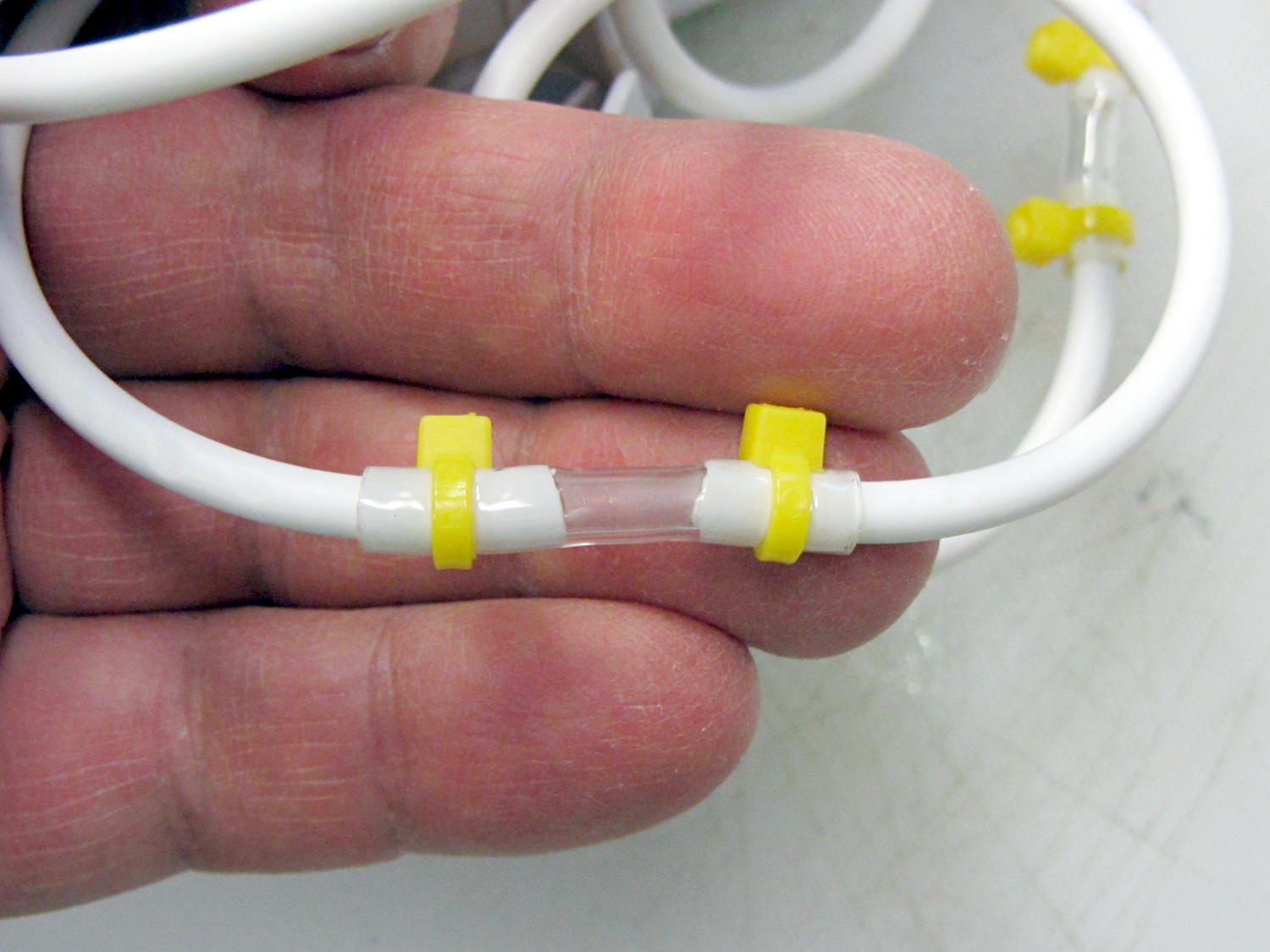
It seems the coiled hose on “water flossers” or “water jet” oral hygene appliances (I can’t even type that with a straight face) lasts about three years, then fails in a spectacular water spray. Mary’s Interplak cleaner just blew a hose, whereupon I discovered that 3/32 inch ID Tygon tubing is a very snug press fit over the 3.8 mm OD white plastic hose:
Patched Interplak tubing
The hose blew out during the early part of a protracted snow storm / cold snap, when driving out for a replacement wasn’t going to happen. This fix, ugly though it may be, has been working well enough that we’ll wait for something else to go wrong.
It’s not clear replacing the entire length of hose with Tygon tubing would work as well, because the rigid hose transmits water pressure pulses from the pump to the tip without much damping. We’re not sure how much that matters and, if the Tygon hack outlasts the OEM hose, maybe we’ll try that.
As you might expect, the hose isn’t a replaceable part. In fact, Interplak doesn’t list any replaceable parts, other than the jet tips, which never seem to wear out…
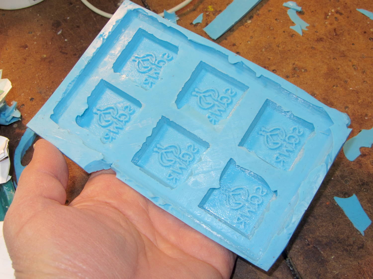
A closeup shows that the characteristic 3D printed striations came through perfectly on the silicone:
SqWr chocolate molds – silicone interior detail
In this application, the 3D printer’s hand-knitted look is desirable, but most molds would benefit from manual smoothing / sanding / filling; perhaps slathering release agent over the molds would help. In any event, the silicone didn’t lock to the striations and parted easily, so it’s all good.
The first layer of silicone worked its way between the positive molds and the slab; Tesa says the positives were so well attached to the pegs that she forgot to apply double-sided tape between them. No harm done: the flashing peeled / trimmed off easily enough.
She thinks a shallow block mold would work just as well for a slab like this: you’d (well, she’d) save hours of tedious layering. The block mold wouldn’t use any more silicone, as the mixing cup had plenty of residue after each layer, even after scraping: doing just one mixing, one pouring, and one curing stage would be a major win.
Solder pretty cable with silver plating on the braid (it’s probably mil-spec Teflon dielectric RG-174 coaxial cable) to the LEDs
Conjure a coax power connector and wall wart
Apply foam squares to mounts
Affix to sewing machine
The front LEDs have a jaunty angle along the bottom of the plastic panel:
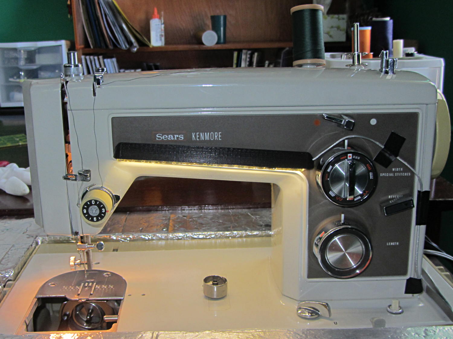
Kenmore Model 158 Sewing Machine – LED Lights – front
You can see why I want cool-white LEDs, rather than these warm-white ones, to match the daylight from the window to the right. The wash of orange light from the incandescent bulb inside the end bell has got to go, too.
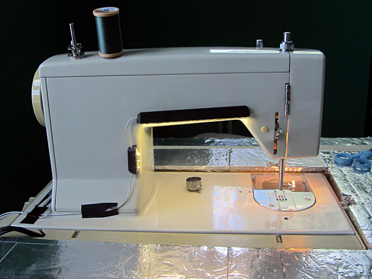
The rear LEDs over the arm may be slightly too close to the opening:
Kenmore Model 158 Sewing Machine – LED Lights – rear
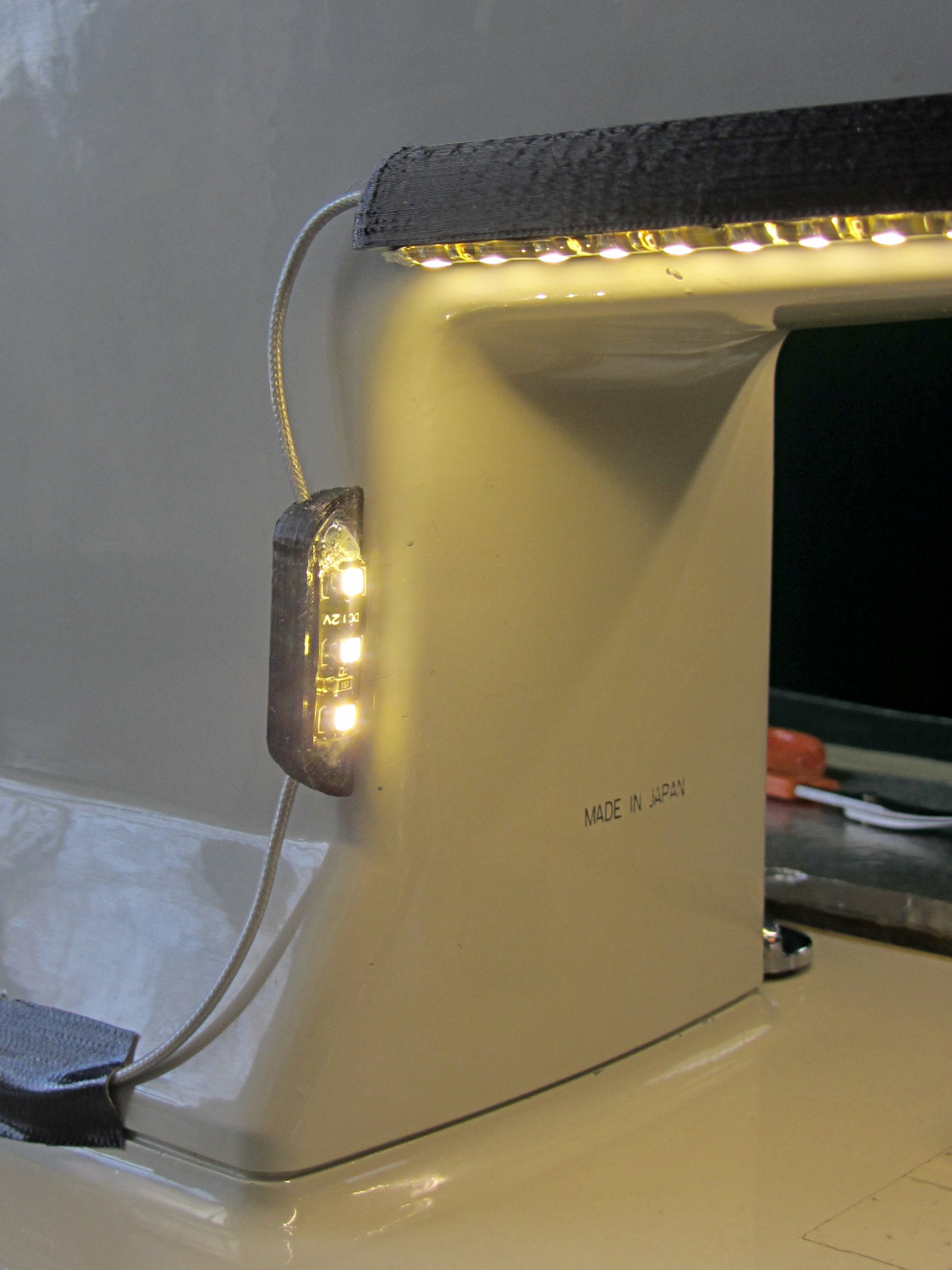
The single-segment strip on the side provides a bit more light for the needle across the opening:
Kenmore Model 158 Sewing Machine – LED Lights – rear detail
Now, I’ll grant you that the strips of of black Gorilla Tape aren’t particularly attractive, but the intent here is to find out whether the LEDs produce enough light, don’t snag the quilt, and generally meet requirements.
After getting two feet of snow over the course of a few days, the snowbank at the end of the driveway absorbed the mailbox:
End of Driveway Snowbank
I try to gnaw a path closer to the mailbox for the USPS delivery truck, but it was pretty much a losing battle against the DOT snowplows.
Later that day, we carved the top off the banks on both sides to improve the sightlines along the road. After a week, we were once again comfortable making a left turn…
For perspective, after the 2011 Snowtober event, the DOT crew parked the shredder in front of the same bushes you can see in the top picture:
What with all the snow this winter, I noticed that the muffler on the snowblower was rattling around something awful; eventually, the blue fire jetting directly from the engine block got to be distracting. Come to find out the bracket attached to the top of the block had ripped free from the muffler:
The two long bolts on the right explain why this particular anomaly didn’t get an immediate repair: they were firmly jammed, deep in the block, and resisted my gentle attempts to free them. For obvious reasons, you (well, I) don’t want to break off the end of a bolt in its tapped hole…
Snowblower muffler – failed bracket
So, over the course of a few weeks, I applied a dose of PB B’laster to the bolts, down deep behind the muffler where they entered the block, and gingerly wiggled the bolts back-and-forth to their ever-increasing limits of travel. Doing that every time I went into the garage guaranteed plenty of excess oil to smoke off the engine during the first few minutes, but ya gotta do what ya gotta do. Two days before the next big storm, the block finally released the bolts. Whew!
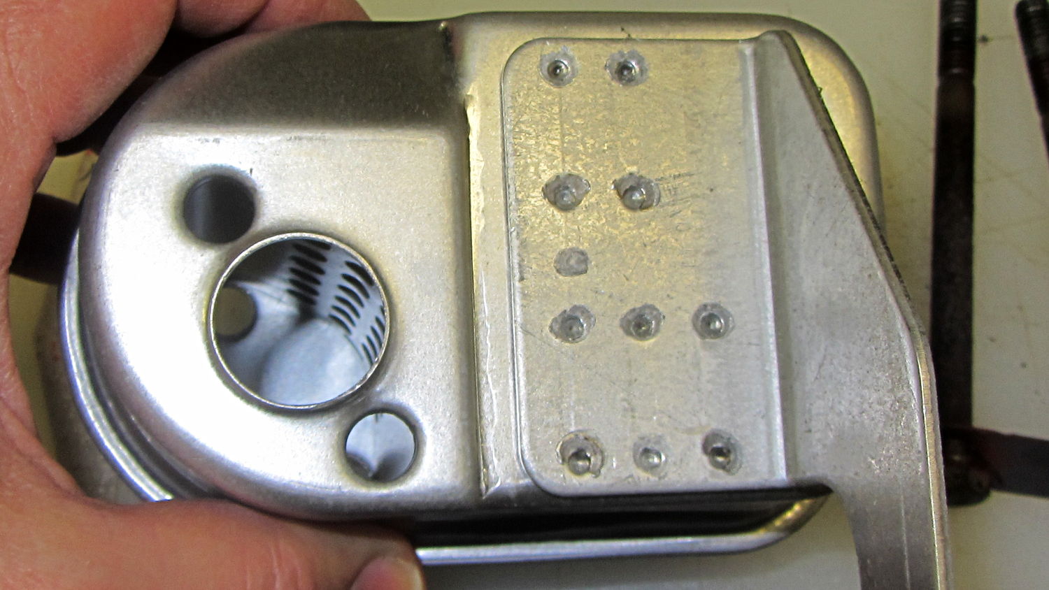
Evidently, having the bracket tear loose wasn’t a rare failure and, perhaps, the situation attracted the attention of someone in accounting who pointed out the warranty repair costs (no, our blower wasn’t in warranty), because the new muffler has a different bracket:
Snowblower muffler – new bracket design
Look at all those spot welds across that huge contact patch!
Yes, I used new bolts with a generous dollop of Never-Seez on each one…
A reversible belt lets me look perfectly natty, regardless of whether I’m wearing my brown pants or my khaki pants. The post joining the buckle and the base worked loose, so the spring wasn’t holding the two parts together; obviously, something must be done.
Loosen the four screws that hold the leather belt in place to reveal what’s inside:
Reversible belt buckle – spring post
Then push the two parts together and give the post a few shots with a sharp punch:
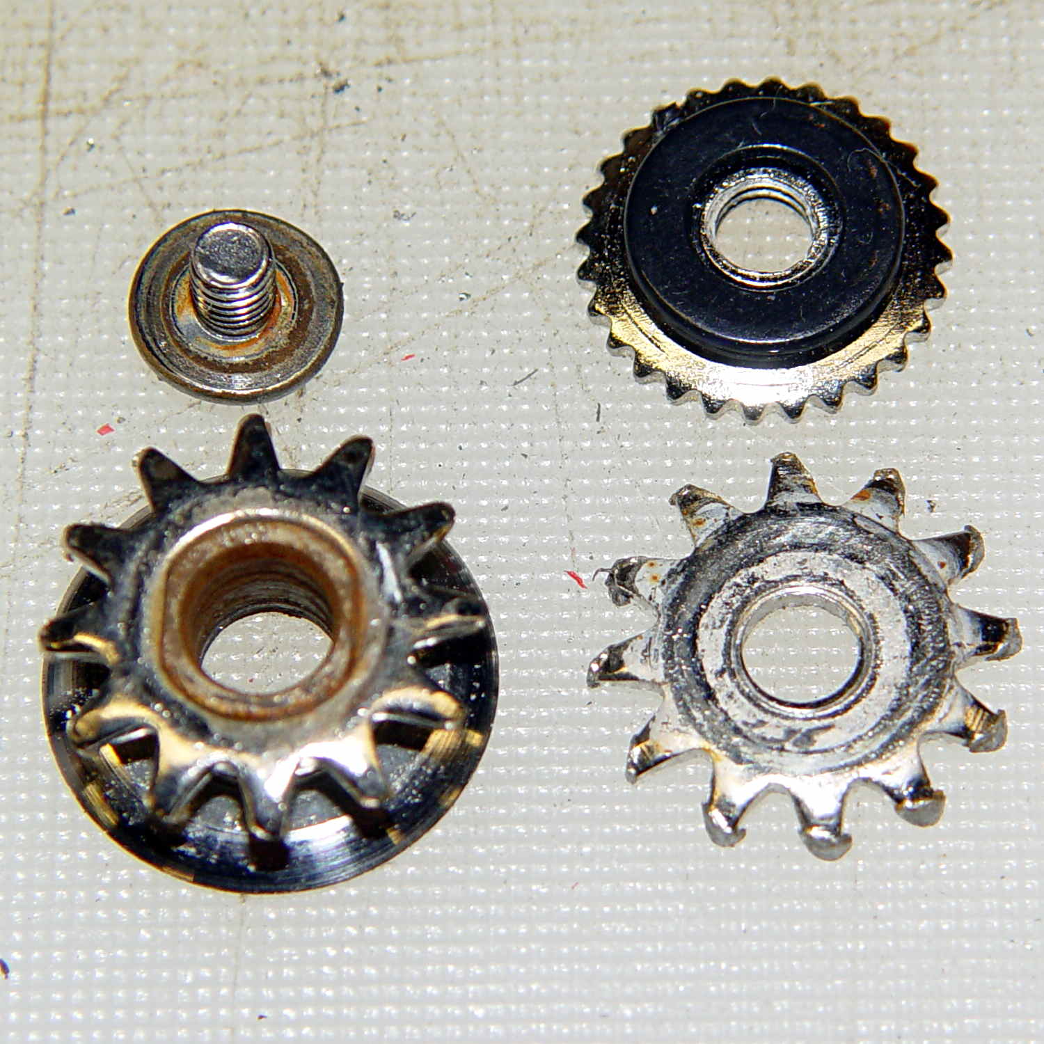
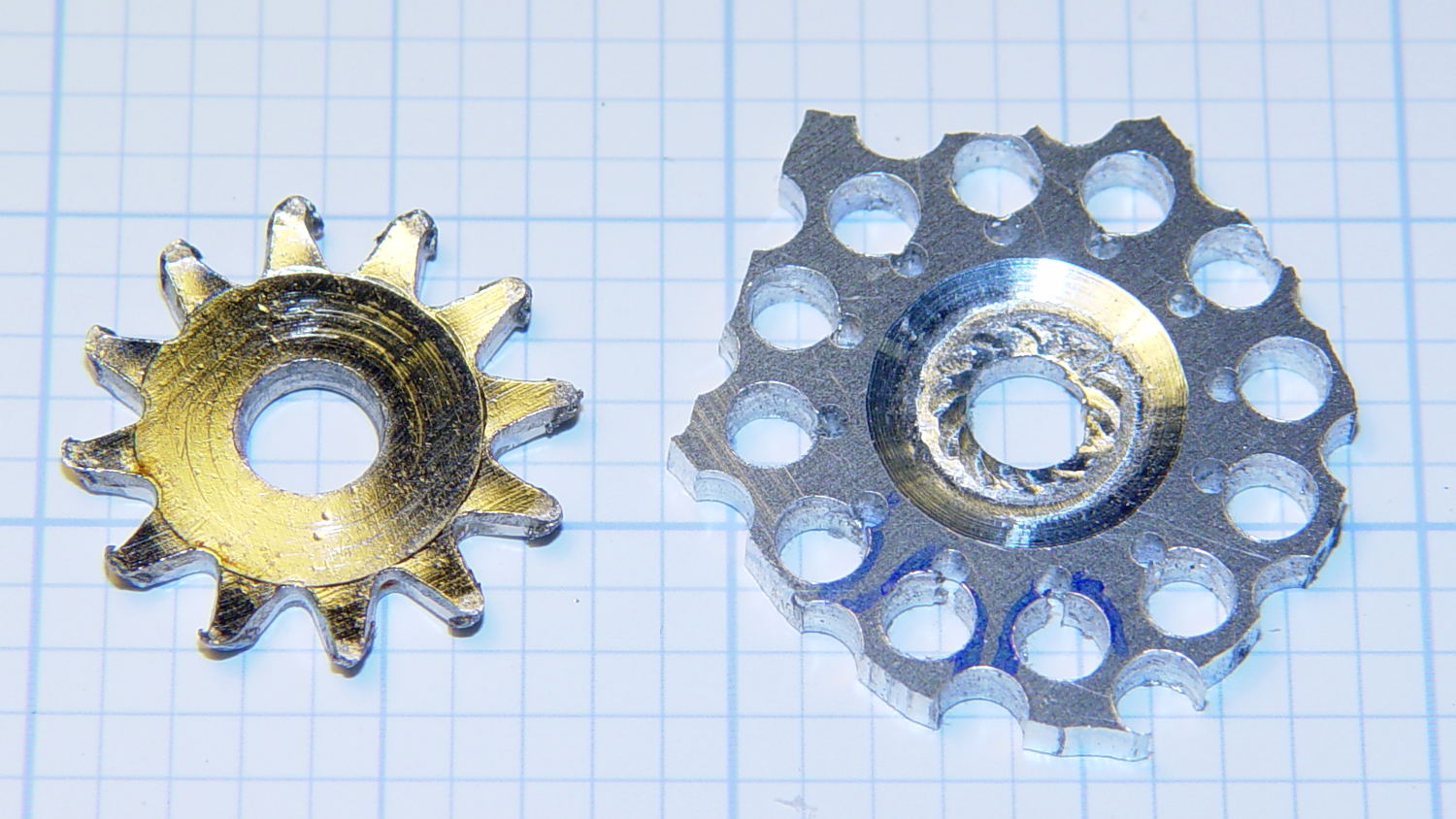
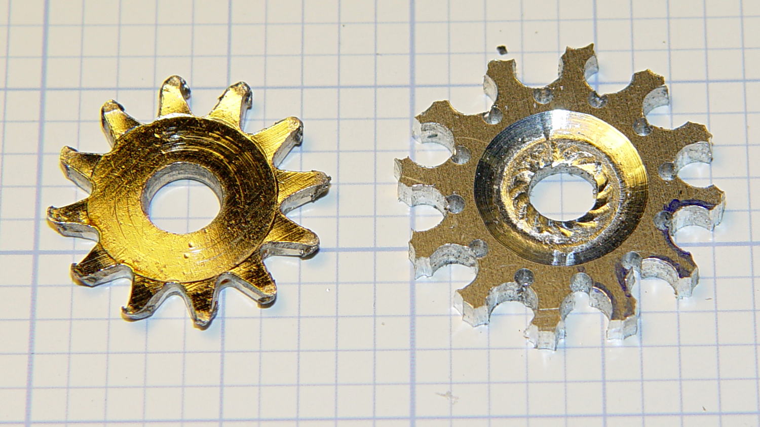
Cleaning up the wrecked gears on the can opener made it painfully obvious that I had to conjure at least one gear to get the poor thing working again:
Can opener – gears and cutters
Fortunately, those are more in the line of cogs, rather than real gears, so I decided a crude hack would suffice: drill a pattern of holes to define the openings between the teeth, file / grind the teeth reasonably smooth, and then tweak the shape to suit.
Fitting some small number-size drills between the remains of the teeth showed:
A #52 = 52.0 mil = 1.32 mm drill matched the root curvature
A #28 = 140.5 mil = 3.57 mm drill was tangent to the small drill and the tooth walls
Neither of those count as precision measurements, particularly given the ruined teeth, but they’re close enough for a first pass.
The OEM drive gear (on the right) has the teeth bent upward to mate with the cutter gear (on the left), but under normal gripping force, the teeth don’t mesh securely and tend to slide over / under / past each other. However, if I were to cut the drive gear from a metal sheet that’s thick enough to engage both the root and the crest of the cutter gear, that should prevent all the slipping & sliding. Some eyeballometric guesstimation suggested 2.5 mm would be about right and the Basement Laboratory Stockpile produced a small slab of 100 mil = 2.54 mm aluminum sheet.
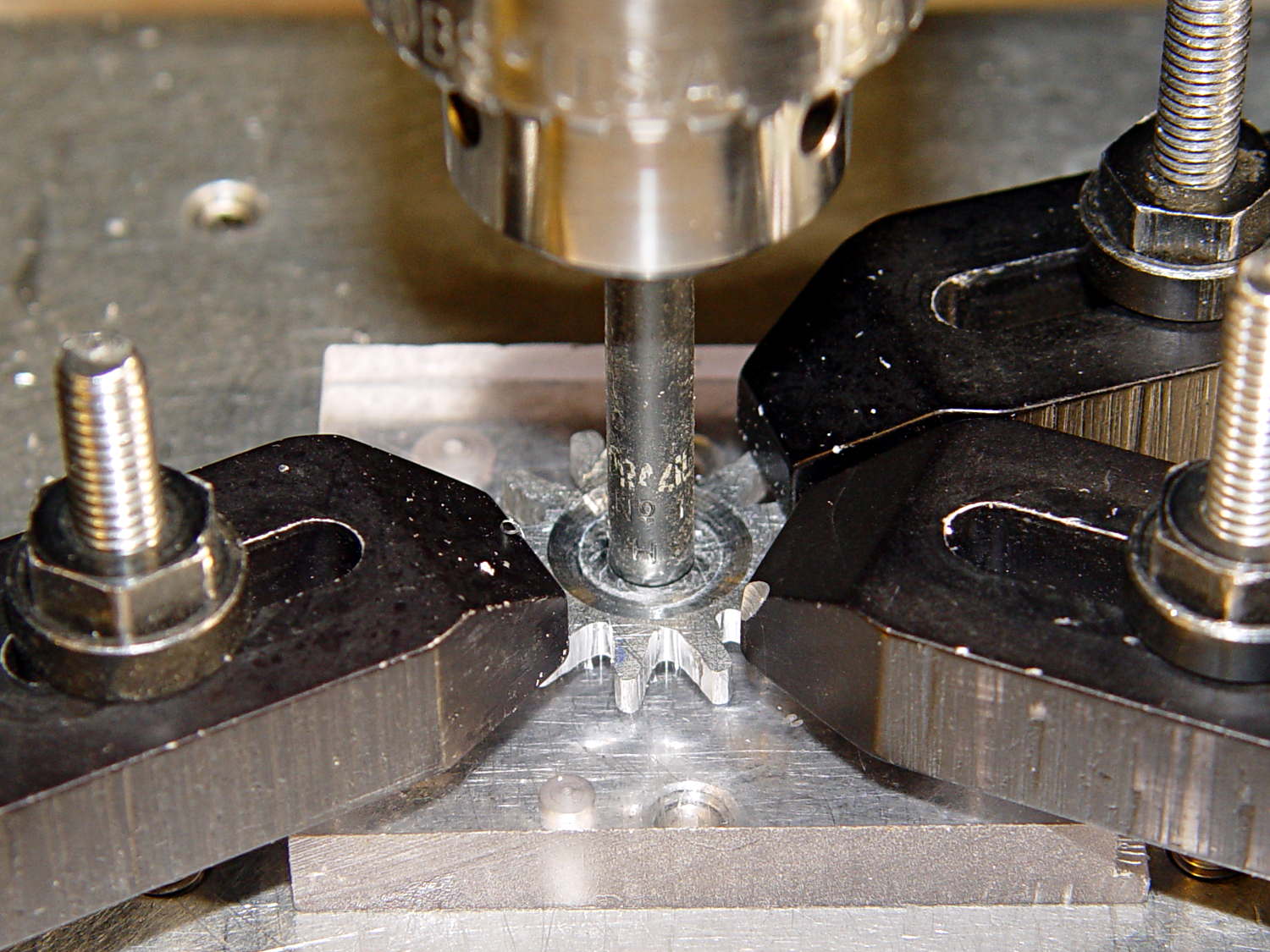
However, the center part of the gear must have the same thickness as the OEM gear to keep the drive wheel at the same position relative to the cutter blade, which means a bit of pocket milling. I have some small ball burrs that seemed like they might come in handy.
A recent thread on the LinuxCNC mailing list announced Bertho Stultien’s gcmc, the G-Code Meta Compiler, and this looked like a golden opportunity to try it out. Basically, gcmc lets you write G-Code programs in a C-like language that eliminates nearly all the horrendous syntactic noise of raw G-Code. I like it a lot and you’ll be seeing more of it around here…
The gcmc source code, down below, include a function that handles automatic tool height probing, using that simple white-goods switch. The literal() function emits whatever you hand it as text for the G-Code file, which is how you mechanize esoteric commands that gcmc doesn’t include in its repertoire. It’s basically the same as my bare G-Code probe routine, but now maintains a state variable that eliminates the need for separate first-probe and subsequent-probe entry points.
One point that tripped me up, even though I should know better: because gcmc is a compiler, it can’t read G-Code parameters that exist only when LinuxCNC (or whatever) is interpreting the G-Code. You can write parameters with values computed at compile time, but you can’t read and process them in the gcmc program.
Anyhow, the first pass produced an array of holes that, as I fully expected, weren’t quite right:
Can opener gear – first hole pattern
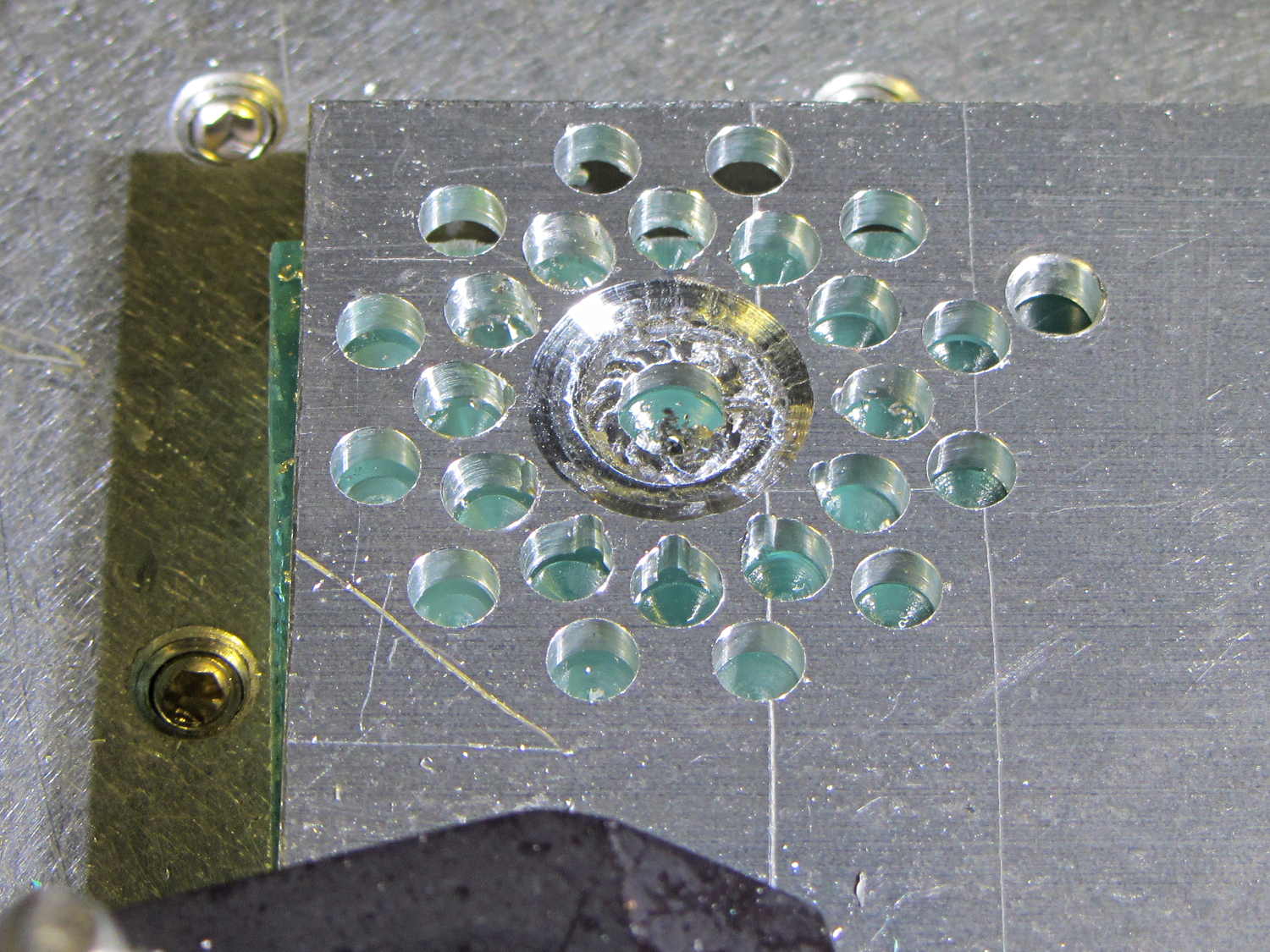
The second pass got the root and middle holes tangent to each other:
Can opener gear – second hole pattern
It also ran a center drill pass for those tiny little holes to prevent their drill from wandering about. The other drills are about the same size as the center drill, so they’re on their own.
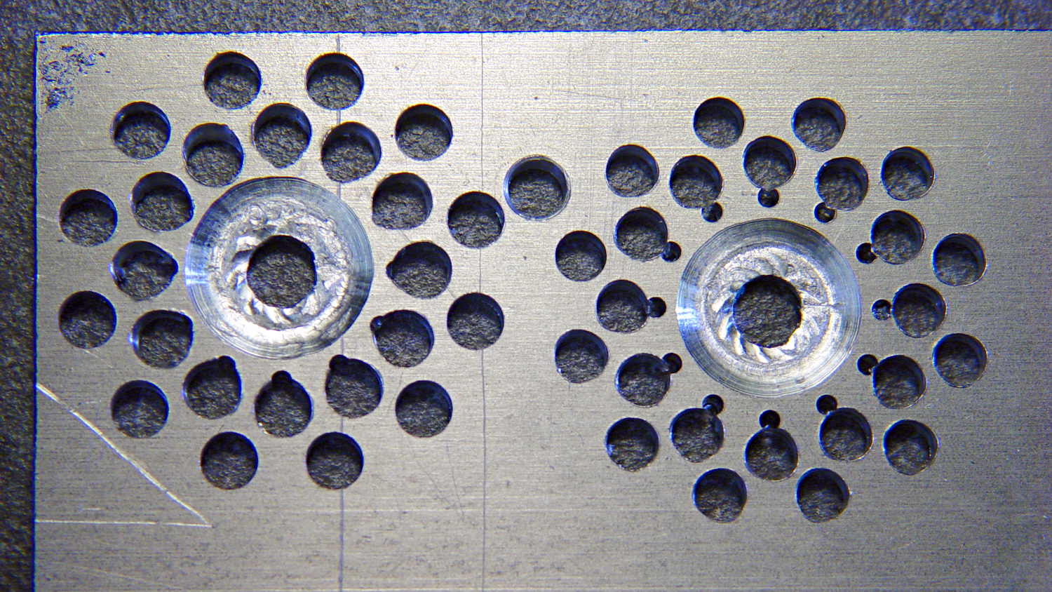
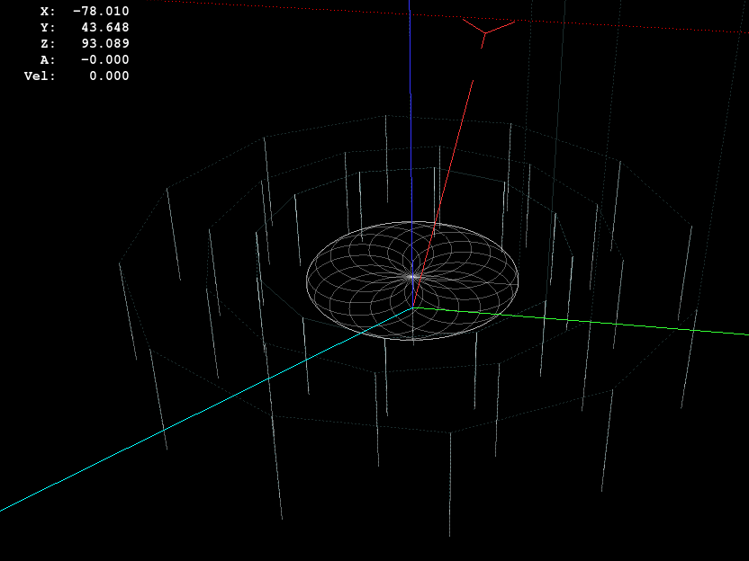
The rosette around the central hole comes from sweeping the burr in a dozen overlapping circles tangent to the outer diameter, then making a cleanup pass around the OD:
Can opener gear – 12 leaf rosette
Incidentally, that stray hole between the two patterns came from the aluminum sheet’s previous life, whatever it may have been. There are three other holes, two of which had flat washers taped to them, so your guess is as good as mine. That’s my story and I’m sticking with it.
Introducing the sheet to Mr Bandsaw and cutting through the outer ring produced a bizarre snowflake:
Can opener gear – cut out
Cutting off the outer ring of holes turned the incipient gear body into a ragged shuriken:
Can opener gear – isolated
A few minutes of increasingly deft Dremel cutoff wheel work, poised on the bench vise over the shopvac nozzle to capture the dust, produced a credible gear shape:
Can opener gear – first pass
Iterating through some trial fits, re-grinds, and general fiddling showed that the center pocket was too shallow. The cutter wheel should slightly clear the drive wheel, but it’s an interference fit:
Can opener gear – trial fit
Which, of course, meant that I had to clamp the [mumble] thing back in the Sherline and re-mill the pocket. The trick is to impale it on the wrong end of a suitable drill, clamp it down, and touch off that spot as the origin:
Can opener gear – re-centering
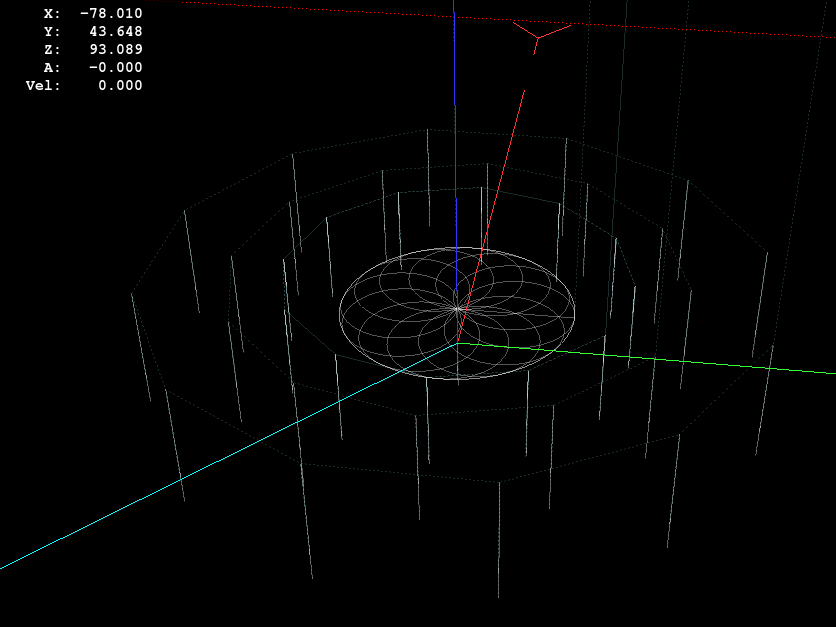
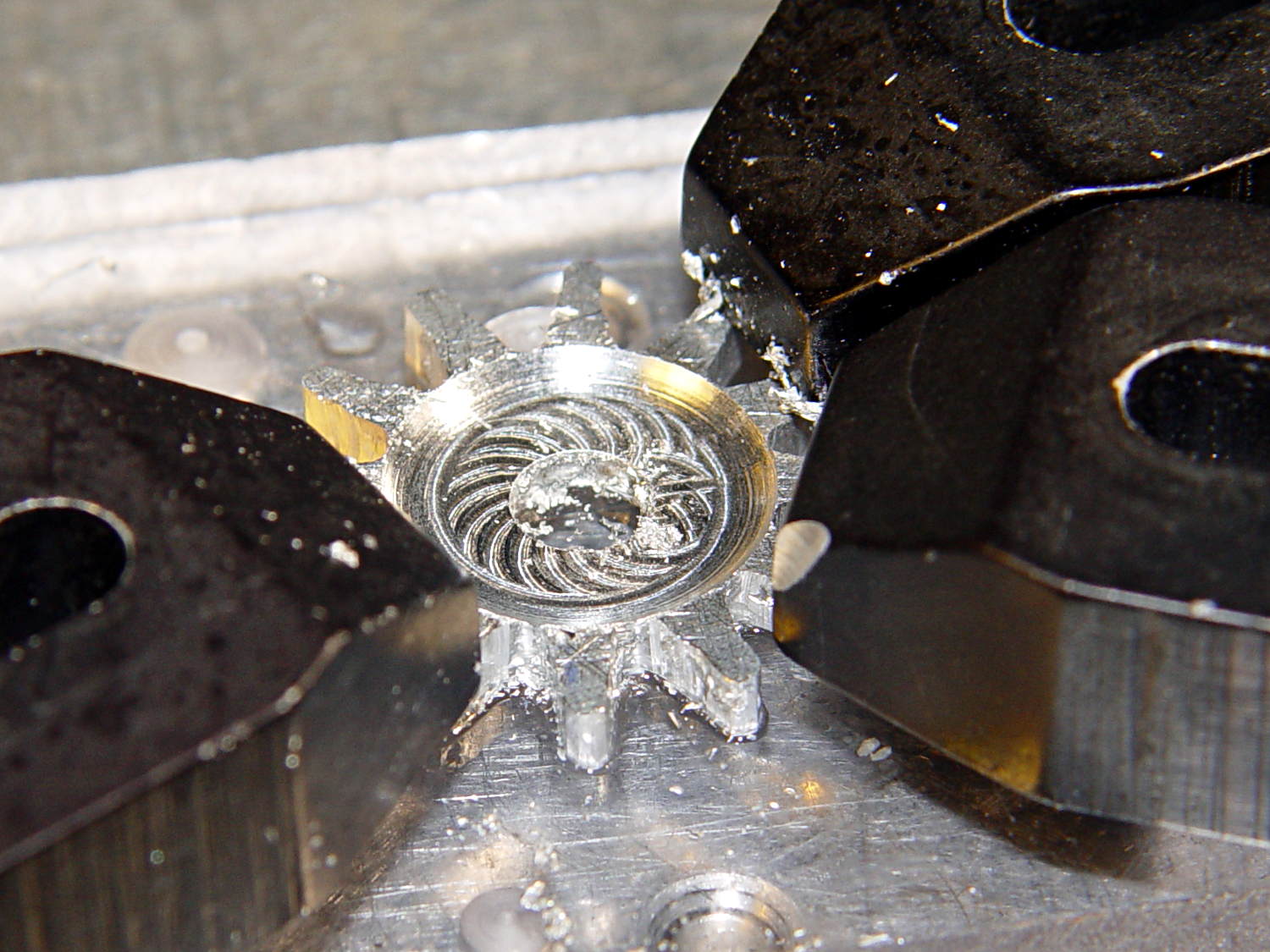
I took the opportunity to switch to a smaller ball and make 16 little circles to clear the pocket:
Can Opener Gear – 16 leaf rosette
Now that’s better:
Can opener gear – deeper pocket
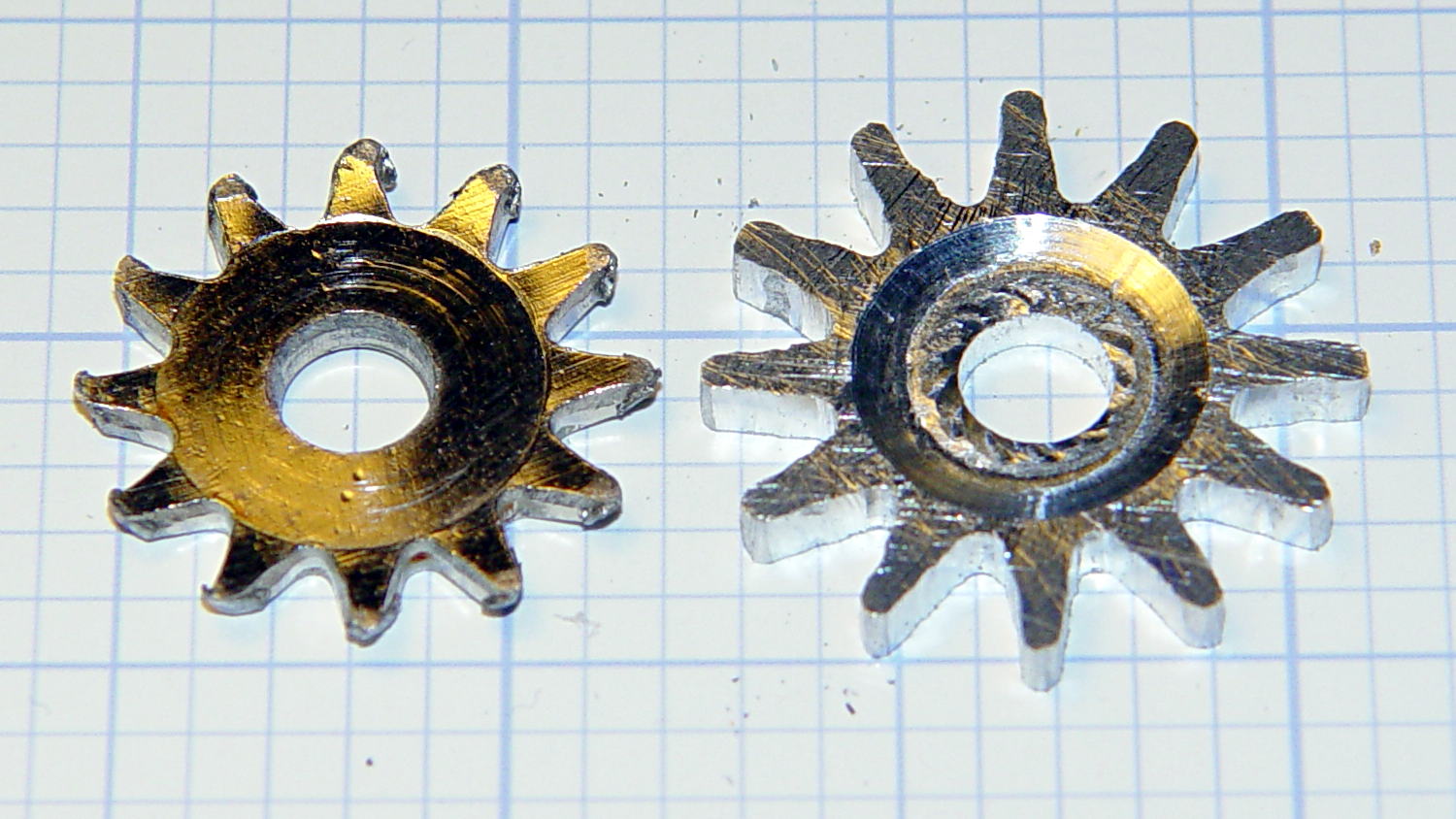
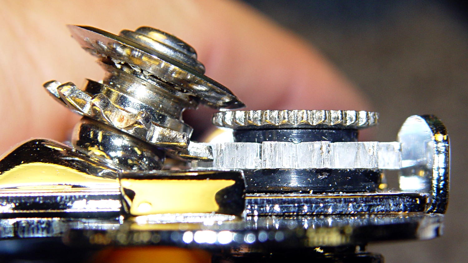
Another trial fit showed that everything ended up in the right place:
Can opener gear – final fit
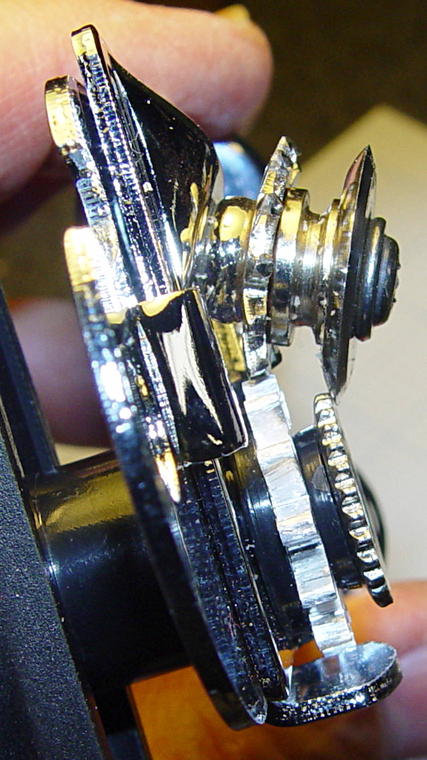
I gave it a few cranks, touched up any cogs that clashed with the (still misshapen) cutter gear, applied it to a randomly chosen can, and it worked perfectly:
Squeeze the levers to easily punch through the lid
Crankety crank on the handle, while experiencing none of the previous drama
The severed lid falls into the can
Which is exactly how it’s supposed to work. What’s so hard about that?
What you can’t see in that picture is the crest of the lowest cutter gear tooth fitting just above the bottom of the drive gear root. Similarly, the crest of the highest drive gear tooth remains slightly above the cutter root. That means the cutter gear teeth always engage the drive gear, there’s no slipping & sliding, and it’s all good.
Aluminum isn’t the right material for a gear-like object meshed with a steel counterpart, but it’s easy to machine on a Sherline. I’ll run off a few more for show-n-tell and, if when this one fails, I’ll have backup.
The gcmc source code:
// Can opener drive gears
//	Ed Nisley KE4ZNU - February 2014
//	Sherline CNC mill with tool height probe
//	XYZ touchoff origin at center on fixture surface

DO_DRILLCENTER	= 1;
DO_MILLCENTER	= 1;
DO_DRILLINNER	= 1;
DO_DRILLOUTER	= 1;
DO_DRILLTIPS	= 1;

//----------
// Overall dimensions

GearThick = 2.54;			// overall gear thickness
GearCenterThick = 1.75;		// thickness of gear center

GearTeeth = 12;				// number of teeth!
ToothAngle = 360deg/GearTeeth;
GearOD = 22.0;				// tooth tip
GearID = 13.25;				// tooth root

SafeZ = 20.0;				// guaranteed to clear clamps
TravelZ = GearThick + 1.0;	// guaranteed to clear plate

//----------
// Tool height probe
//	Sets G43.1 tool offset in G-Code, so our Z=0 coordinate always indicates the touchoff position

ProbeInit = 0;					// 0 = not initialized, 1 = initialized
ProbeSpeed = 400.0mm;
ProbeRetract = 1.0mm;

PROBE_STAY = 0;					// remain at probe station
PROBE_RESTORE = 1;				// return to previous location after probe

function ProbeTool(RestorePos) {

local WhereWasI;

	WhereWasI = position();

	if (ProbeInit == 0) {		// probe with existing tool to set Z=0 as touched off
		ProbeInit++;
		literal("#<_Probe_Speed> = ",to_none(ProbeSpeed),"\n");
		literal("#<_Probe_Retract> = ",to_none(ProbeRetract),"\n");
		literal("#<_ToolRefZ> = 0.0 \t; prepare for first probe\n");
		ProbeTool(PROBE_STAY);
		literal("#<_ToolRefZ> = #5063 \t; save touchoff probe point\n");
		literal("G43.1 Z0.0 \t; set zero offset = initial touchoff\n");
	}
	elif (ProbeInit == 1) {		// probe with new tool, adjust offset accordingly
		literal("G49 \t; clear tool length comp\n");
		literal("G30 \t; move over probe switch\n");
		literal("G59.3 \t; use coord system 9\n");
		literal("G38.2 Z0 F#<_Probe_Speed> \t; trip switch on the way down\n");
		literal("G0 Z[#5063 + #<_Probe_Retract>] \t; back off the switch\n");
		literal("G38.2 Z0 F[#<_Probe_Speed> / 10] \t; trip switch slowly\n");
		literal("#<_ToolZ> = #5063 \t; save new tool length\n");
		literal("G43.1 Z[#<_ToolZ> - #<_ToolRefZ>] \t; set new length\n");
		literal("G54 \t; return to coord system 0\n");
		literal("G30 \t; return to safe level\n");
	}
	else {
		error("*** ProbeTool sees invalid ProbeInit: ",ProbeInit);
		comment("debug,*** ProbeTool sees invalid ProbeInit: ",ProbeInit);
		ProbeInit = 0;
	}

	if (RestorePos == PROBE_RESTORE) {
		goto(WhereWasI);
	}

}

//----------
// Utility functions

function WaitForContinue(MsgStr) {
	comment(MsgStr);
	pause();
}

function CueToolChange(MsgStr) {
	literal("G0 Z" + SafeZ + "\n");
	literal("G30\n");
	WaitForContinue(MsgStr);
}

function ToolChange(Info,Name) {
	CueToolChange("msg,Insert " + to_mm(Info[TOOL_DIA]) + " = " + to_in(Info[TOOL_DIA]) + " " + Name);
	ProbeTool(PROBE_STAY);

	WaitForContinue("msg,Set spindle to " + Info[TOOL_SPEED] + " rpm");
	feedrate(Info[TOOL_FEED]);
}

function GetAir() {
	goto([-,-,SafeZ]);
}

//-- compute drill speeds & feeds based on diameter
//		rule of thumb is 100 x diameter at 3000 rpm for real milling machines
//		my little Sherline's Z axis can't produce enough thrust for that!

MaxZFeed = 600.0mm;				// fastest possible Z feed

TOOL_DIA = 0;					// Indexes into DrillParam() result
TOOL_SPEED = 1;					//  spindle RPM
TOOL_FEED = 2;					//	linear feed
TOOL_TIP = 3;					//	length of 118 degreee drill tip

function DrillParam(Dia) {
local RPM,Feed,Tip,Data,Derating;

	Derating = 0.25;			// derate from (100 x diameter) max feed

	RPM = 3000.0;				// default 3 k rpm

	Feed = Derating * (100.0 * Dia);
	if (Feed > MaxZFeed) {
		RPM *= (MaxZFeed / Feed);	//  scale speed downward to fit
		Feed = MaxZFeed;
	}

	Tip = (Dia/2) * tan(90deg - 118deg/2);
	Data = [Dia,RPM,Feed,Tip];

	message("DrillParam: ",Data);
	return Data;
}

//-- peck drilling cycle

function PeckDrill(Endpt,Retract,Peck) {
	literal("G83 X",to_none(Endpt[0])," Y",to_none(Endpt[1])," Z",to_none(Endpt[2]),
			" R",to_none(Retract)," Q",to_none(Peck),"\n");
}

//----------
// Make it happen

literal("G99\t;  retract to R level, not previous Z\n");

WaitForContinue("msg,Verify: G30 position in G54 above tool change switch?");

WaitForContinue("msg,Verify: fixture origin XY touched off at center of gear?");

WaitForContinue("msg,Verify: Z touched off on top surface at " + GearThick + "?");
ProbeTool(PROBE_STAY);

//-- Drill center hole

if (DO_DRILLCENTER) {

	DrillData = DrillParam(5.0mm);
	ToolChange(DrillData,"drill");

	goto([0,0,-]);
	goto([-,-,TravelZ]);

	drill([0,0,-1.5*DrillData[TOOL_TIP]],TravelZ,DrillData[TOOL_DIA]);
	GetAir();

}

//-- Drill inner ring

if (DO_DRILLINNER) {

	DrillData = DrillParam(1.32mm);

	RingRadius = GearID/2.0 + DrillData[TOOL_DIA]/2.0;		// center of inner ring holes
	HolePosition = [RingRadius,0mm,-1.5*DrillData[TOOL_TIP]];

//	but first, center-drill to prevent drifting

	CDData = DrillParam(1.00mm);			// pretend it's a little drill
	CDData[TOOL_FEED] = 100mm;				//  ... use faster feed

	CDPosition = HolePosition;				// use center drill coordinates
	CDPosition[2] = GearThick - 0.25mm;		//  ... just below surface

	ToolChange(CDData,"center drill");

	goto([0,0,-]);
	goto([-,-,TravelZ]);

	for (Tooth = 0 ; Tooth < GearTeeth ; Tooth++) {
		drill(CDPosition,TravelZ,2*TravelZ);		// large increment ensures one stroke
		CDPosition = rotate_xy(CDPosition,ToothAngle);
	}

//	now drill the holes

	ToolChange(DrillData,"drill");

	goto([0,0,-]);
	goto([-,-,TravelZ]);

	for (Tooth = 0 ; Tooth < GearTeeth ; Tooth++) {
		PeckDrill(HolePosition,TravelZ,DrillData[TOOL_DIA]);
		HolePosition = rotate_xy(HolePosition,ToothAngle);
	}

	GetAir();

}

//-- Mill center recess

if (DO_MILLCENTER) {

	MillData = [4.50mm,3000,250.0mm,0.0mm];			// spherical ball burr

	Delta = GearThick - GearCenterThick;							// depth to be milled away
	Inset = sqrt(2.0*Delta*(MillData[TOOL_DIA]/2) - pow(Delta,2));	// toll axis to milled edge

	ToolChange(MillData,"ball burr");

	goto([0,0,-]);							// above central hole
	goto([0,0,GearThick]);					// vertically down to flush with surface
	move([0,0,GearCenterThick]);			// into gear blank

	for (Angle = 0.0deg; Angle < 360.0deg; Angle+=360.0deg/16) {	// clear interior
		circle_cw((GearID/2 - Inset)/2,Angle);
	}

	move_r([(GearID/2 - Inset),0.0,0.0]);							// clean rim
	circle_ccw([0.0,0.0,GearCenterThick],2);

	GetAir();

}

//-- Drill outer ring

if (DO_DRILLOUTER) {

	RingRadius += DrillData[TOOL_DIA]/2;		// at OD of inner ring holes

	DrillData = DrillParam(3.18mm);
	RingRadius += DrillData[TOOL_DIA]/2.0;		// center of outer ring holes
	HolePosition = [RingRadius,0mm,-1.5*DrillData[TOOL_TIP]];

	ToolChange(DrillData,"drill");

	for (Tooth = 0 ; Tooth < GearTeeth ; Tooth++) {
		PeckDrill(HolePosition,TravelZ,DrillData[TOOL_DIA]);
		HolePosition = rotate_xy(HolePosition,ToothAngle);
	}

	GetAir();

}

//-- Drill to locate gear tooth tip end

if (DO_DRILLTIPS) {

	DrillData = DrillParam(4.22mm);

	RingRadius = GearOD/2.0 + DrillData[TOOL_DIA]/2.0;		// tangent to gear tooth tip
	HolePosition = [RingRadius,0mm,-1.5*DrillData[TOOL_TIP]];
	HolePosition = rotate_xy(HolePosition,ToothAngle/2);	// align to tooth

	ToolChange(DrillData,"drill");

	for (Tooth = 0 ; Tooth < GearTeeth ; Tooth++) {
		PeckDrill(HolePosition,TravelZ,DrillData[TOOL_DIA]);
		HolePosition = rotate_xy(HolePosition,ToothAngle);
	}

	GetAir();

}

literal("G30\n");
comment("msg,Done!");
The original doodle that suggested the possibility:
Can Opener Gears – Doodle 1
The chord equation at the bottom shows how to calculate the offset for the ball burr, although it turns out there’s no good way to measure the cutting diameter of the burr and it’s not really spherical anyway.
A more detailed doodle with the key line at a totally bogus angle:
Can Opener Gears – Doodle 2
The diagram in the lower right corner shows how you figure the length of the tip on a 118° drill point, which you add to the thickness of the plate in order to get a clean hole.