I’m producing more Tux chocolates with the 16 cavity silicone mold, so I dumped four bags (each with 50 g of chocolate chips) into a big pot of tepid water:
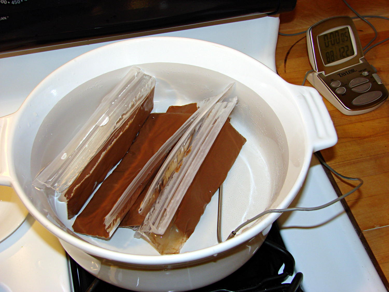
I taped them closed to ensure the zip tops didn’t come unzipped while squeezing the chocolate, which worked out quite well: highly recommended.
Based on previous experience, I paid a bit more attention to the water temperature and kept it at 88±1 °F, transferring a cup or two at a time between this pot and the slightly hotter water (about 95 °F) in another pot. Although I’m sure a closed-loop sous vide bath would maintain tighter tolerances, I’m also sure that wouldn’t make any real difference in this operation.
I also wore thin white cotton gloves, in an attempt to prevent my hands from warming the chocolate above the proper temperature while squeezing the bags. That probably didn’t make any difference, because you must get pretty chummy with the bags and the gloves didn’t amount to much.
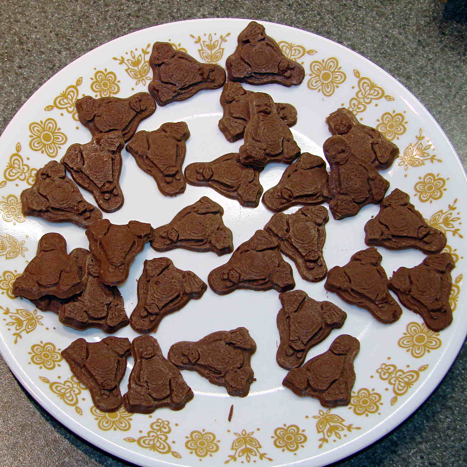
The results, just after extracting the second set of 16 chocolates (minus some, ah, shrinkage), looks pretty good:
I called it quits for the evening, extracted the two unopened bags from the bath, and let them cool overnight. The next morning revealed an interesting sight:
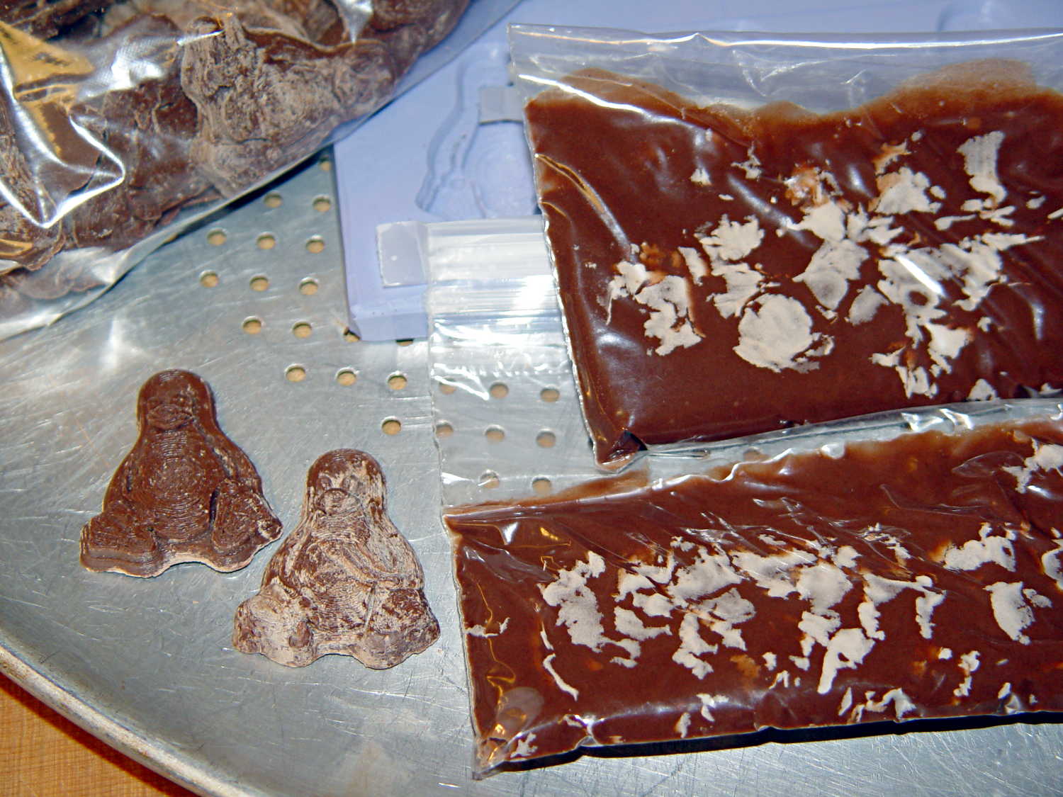
Now, I’d kneaded all the bags to mash the melting chocolate chips together and squeeze out the air, but hadn’t done much more than that. The patches of white cocoa butter seem to correspond to individual chips within the melted mass, so it’s not entirely a temperature thing; I don’t see how to make an individual chip hotter (or colder) than everything else in the bag.
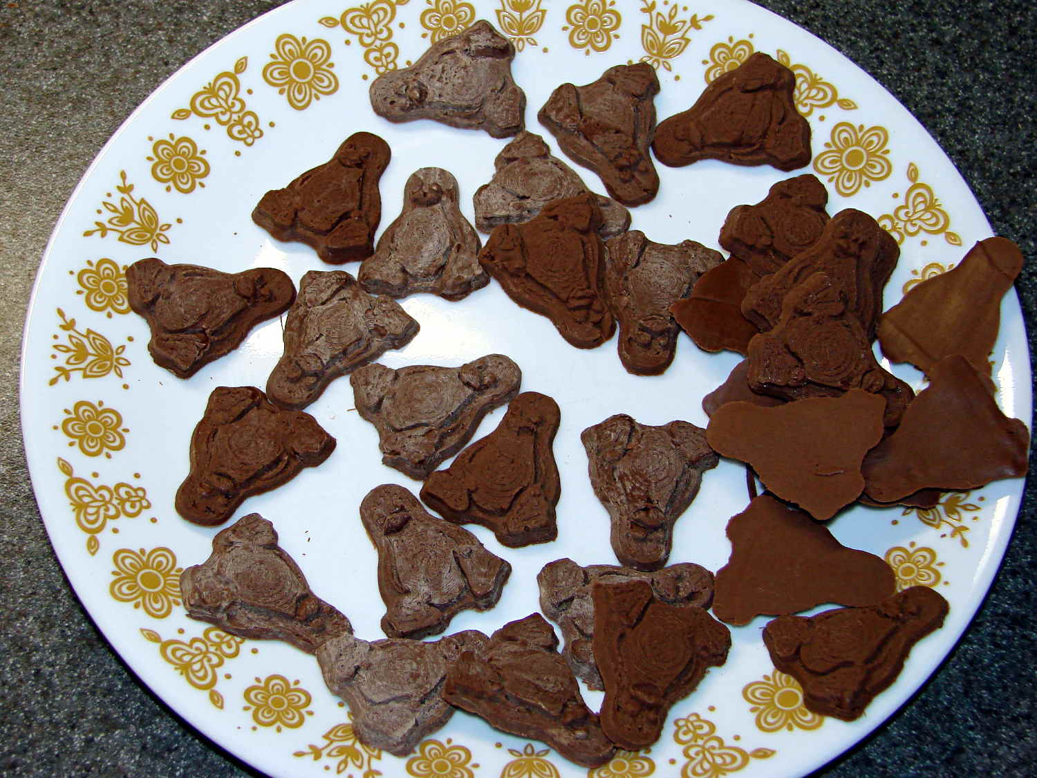
Remelting those two bags the next morning produced these Tuxen, with the very brown ones having just emerged from the mold:
The proper temperature for dark chocolate is about two degrees higher than for milk chocolate, so I boosted the water bath from 88 °F to 90 °F and dropped in four bags of dark chocolate chips.
At those low temperatures, the chocolate resembles putty, rather than honey, and requires firm pressure on the bags. I think the close contact with my fingers, even with gloves, raises the temperature too much; the chocolate isn’t untempered (I think that’s the right word; “distempered” sounds much more ominous), but it may be more prone to blooming.
Thinking that the silicone mold might chill the chocolate too rapidly, I put a warming pad under the aluminum pizza pad, brought the silicone slab up to about 85 °F, and found that the chocolate molded much more readily. Cooling the mold to 72 °F, just over room temperature, took quite a while.
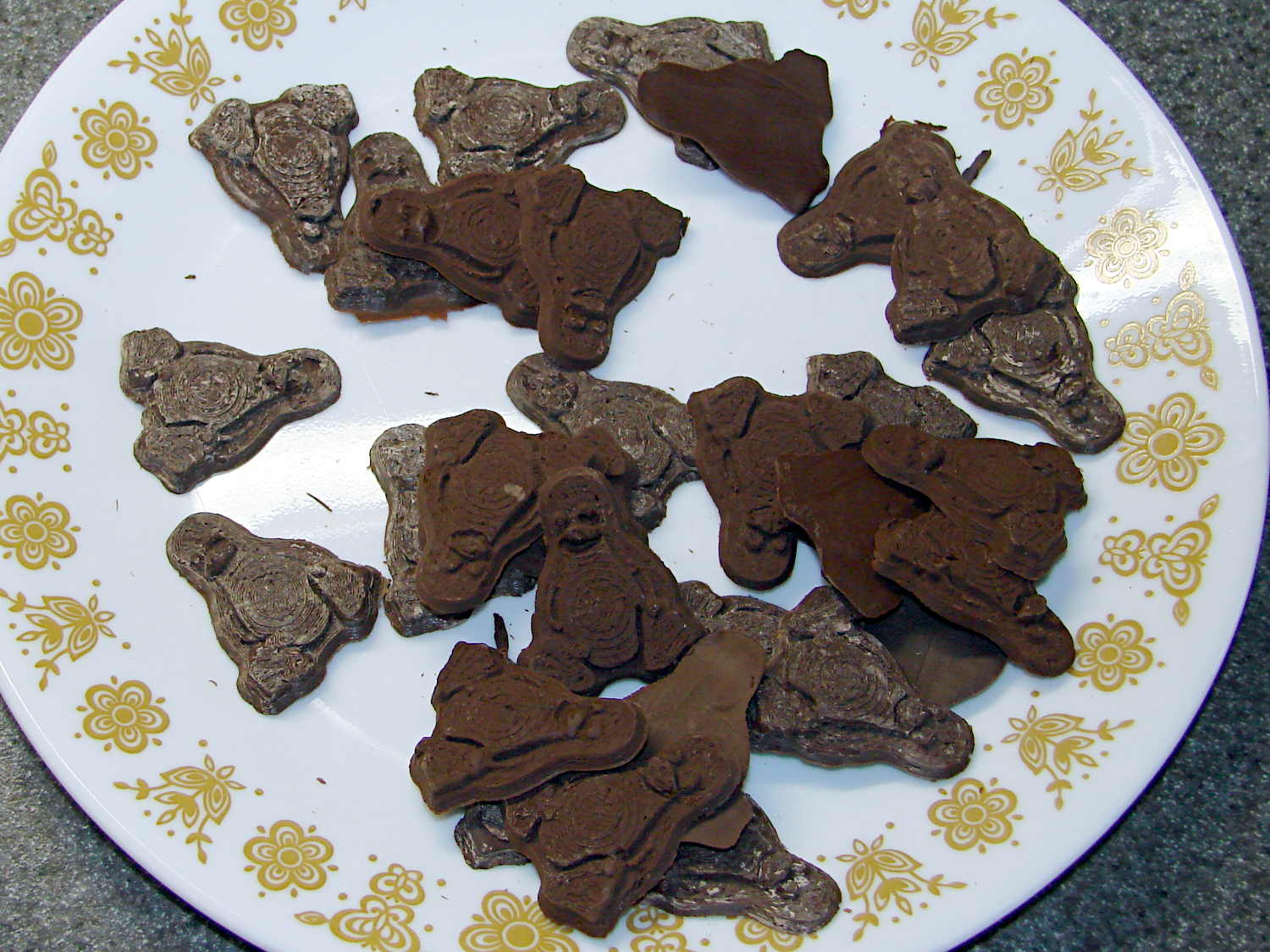
The first dark chocolate Tuxen were already blooming when the second set emerged:
I tried cooling the mold by putting a damp towel under the pizza pan, with equivocal results: the last two sets of dark chocolate bloomed about as rapidly as the first.
It is, perhaps, significant, that the blooming seems confined to the chocolate surfaces in contact with the mold. The flat back surface of each Tux remains in good condition, which suggests that the mold temperature is more critical than I expect.
So my process, such as it is, doesn’t produce good results. Obviously, I need more practice…