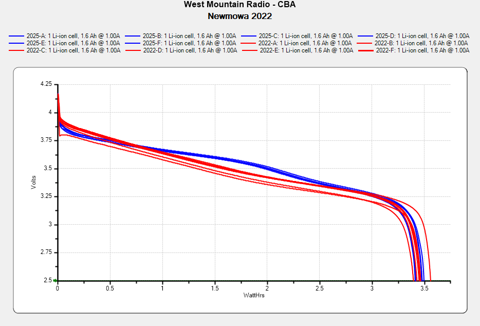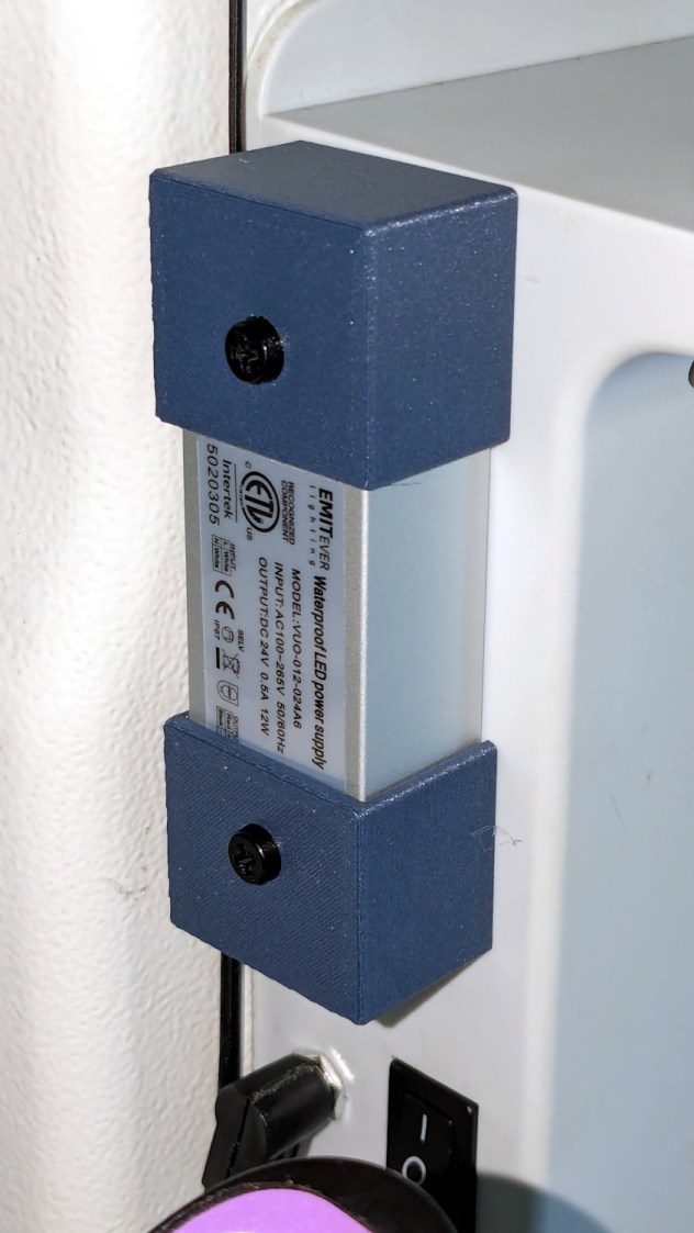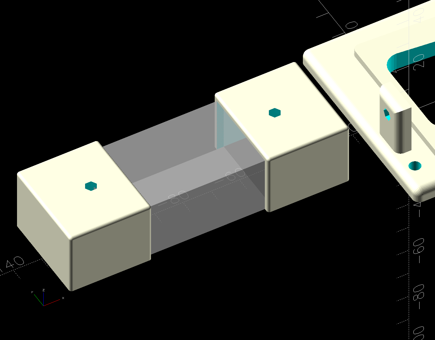
Having harvested the COB LED lighting from the Kenmore 158 Mary gave to a friend, I took advantage of a sewing pause to install the hardware on the 158 she now uses:
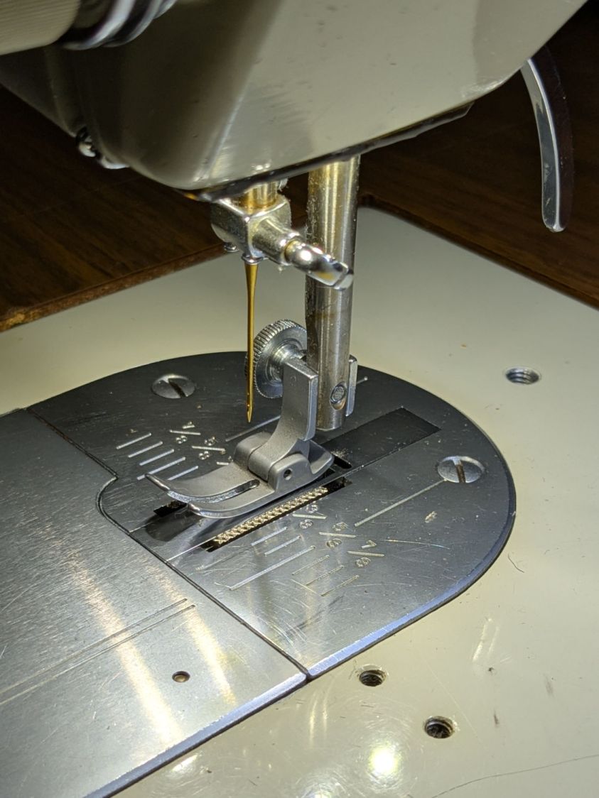
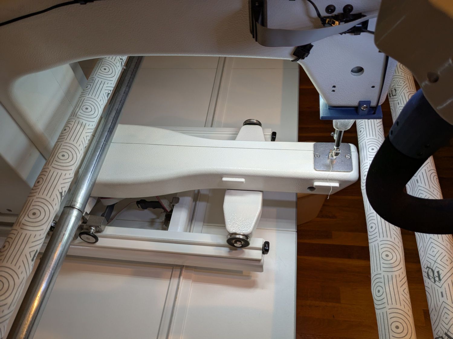
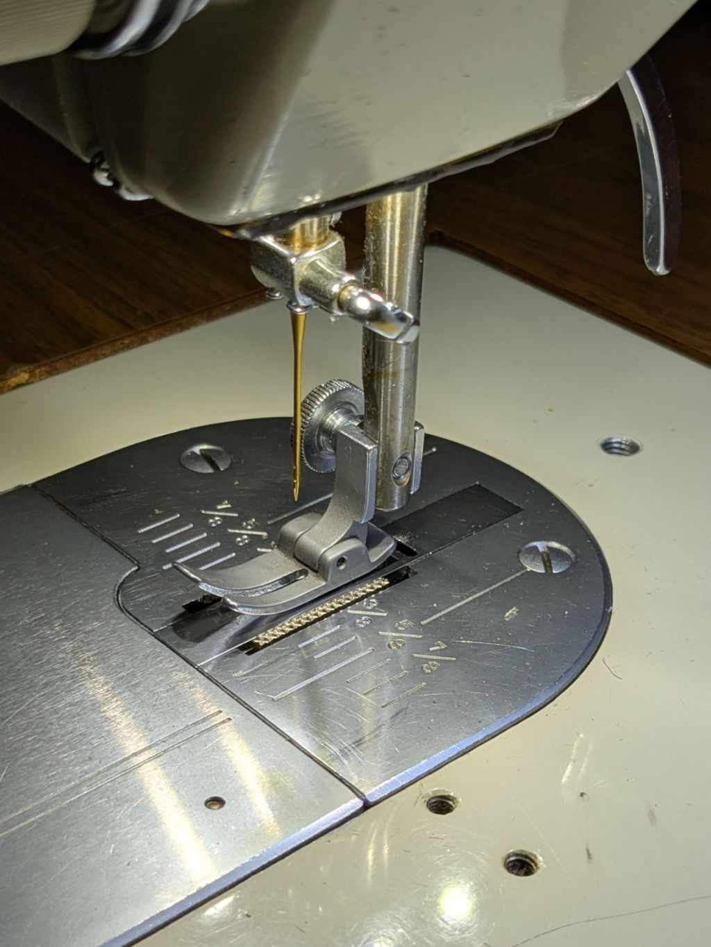
That’s the sandblasted presser foot atop the original glare-y metal plates.
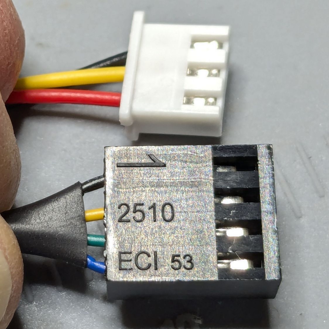
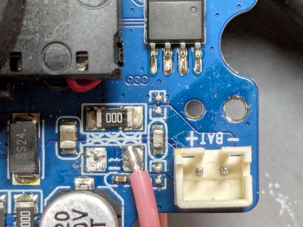
For the record, this is inside the machine’s power connector:
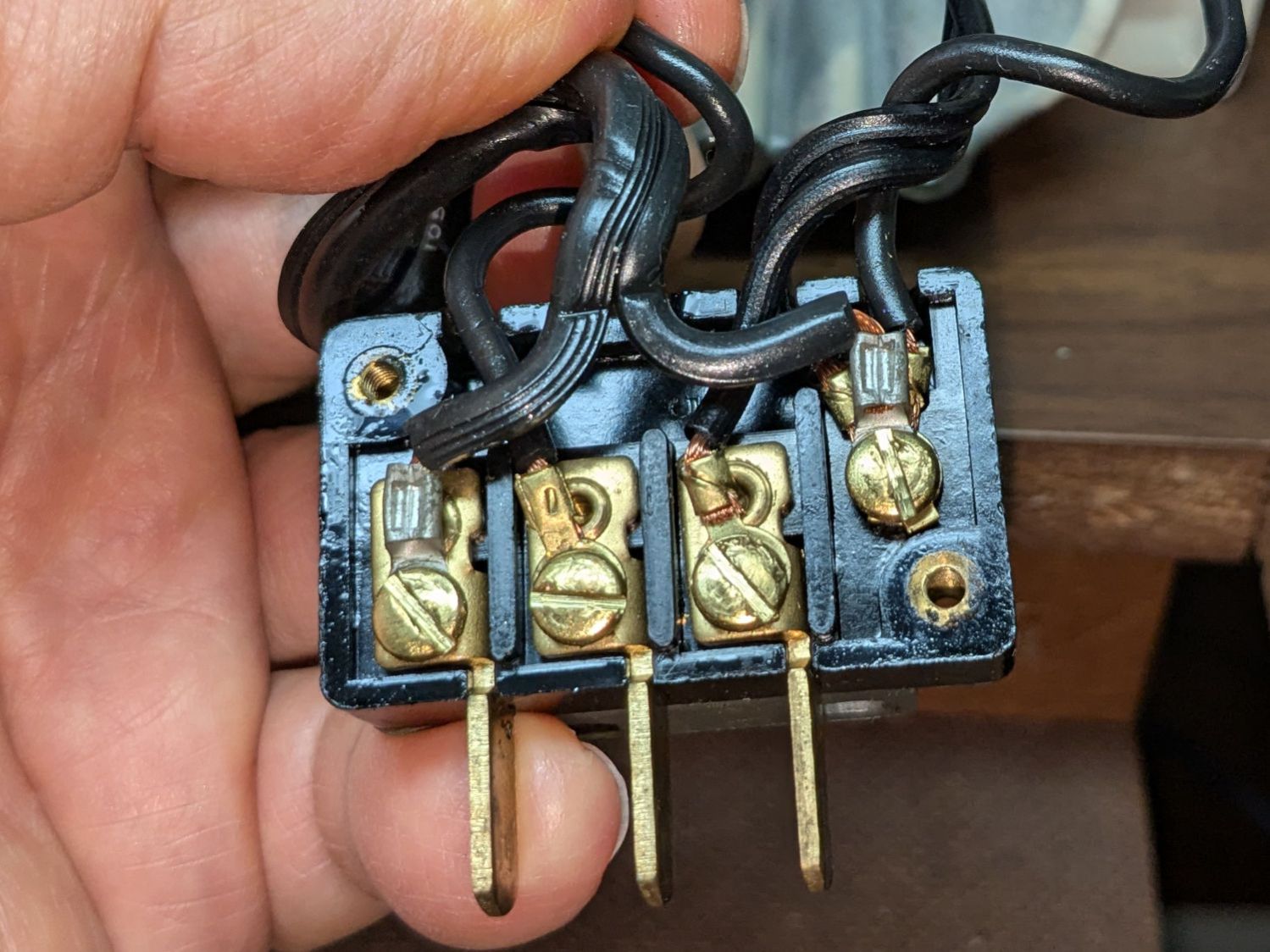
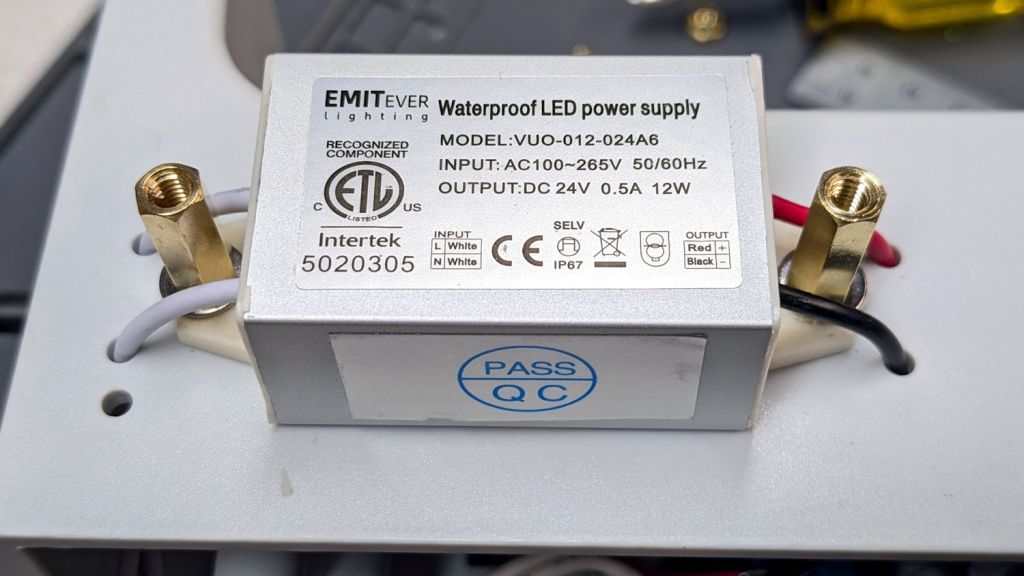
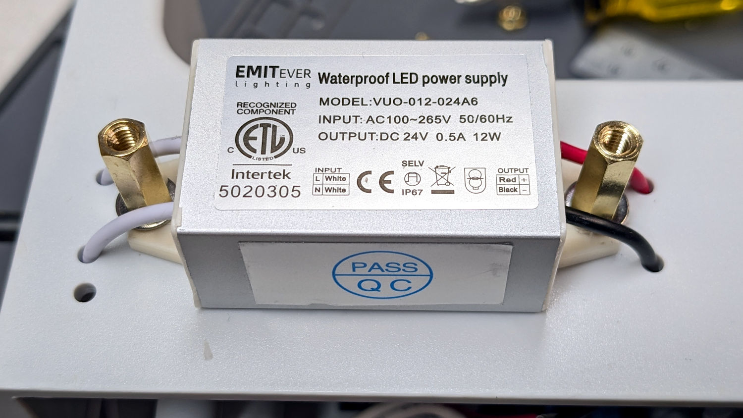
Power for the original glowworm incandescent light comes from the two rightmost terminals: 120 VAC switched by the machine’s power button. Those terminals now go to a new, much more flexy, cable for the 12 VDC power supply, with a step-up supply for the needle LEDs.
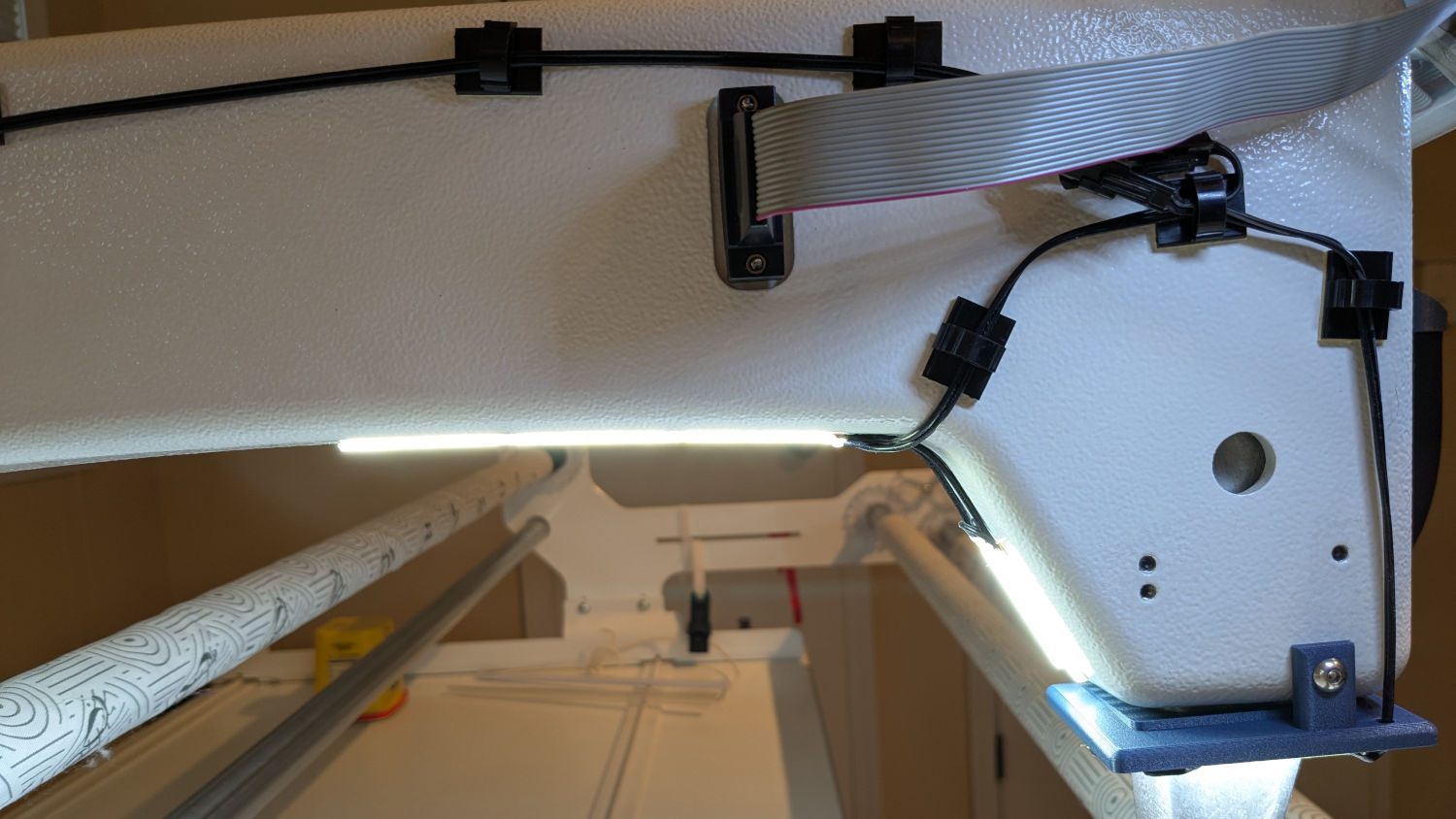
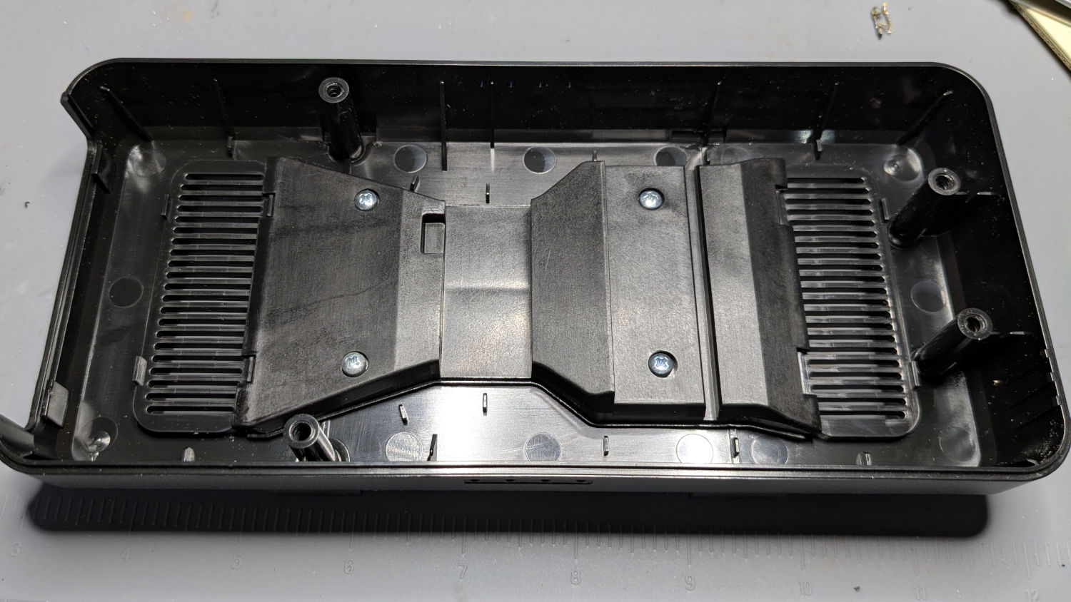
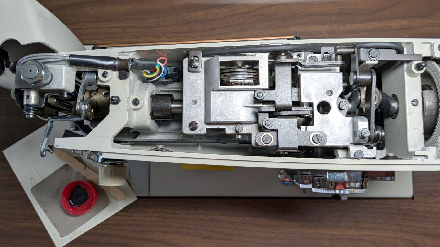
An overview of the wire routing:
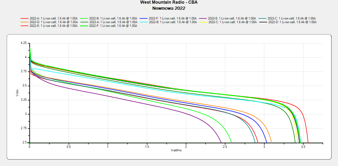
There’s now a 9-pin JST SM connector between the repurposed serial cable and the LEDs, mostly so I can add another light bar to the front in the unlikely event it becomes necessary.
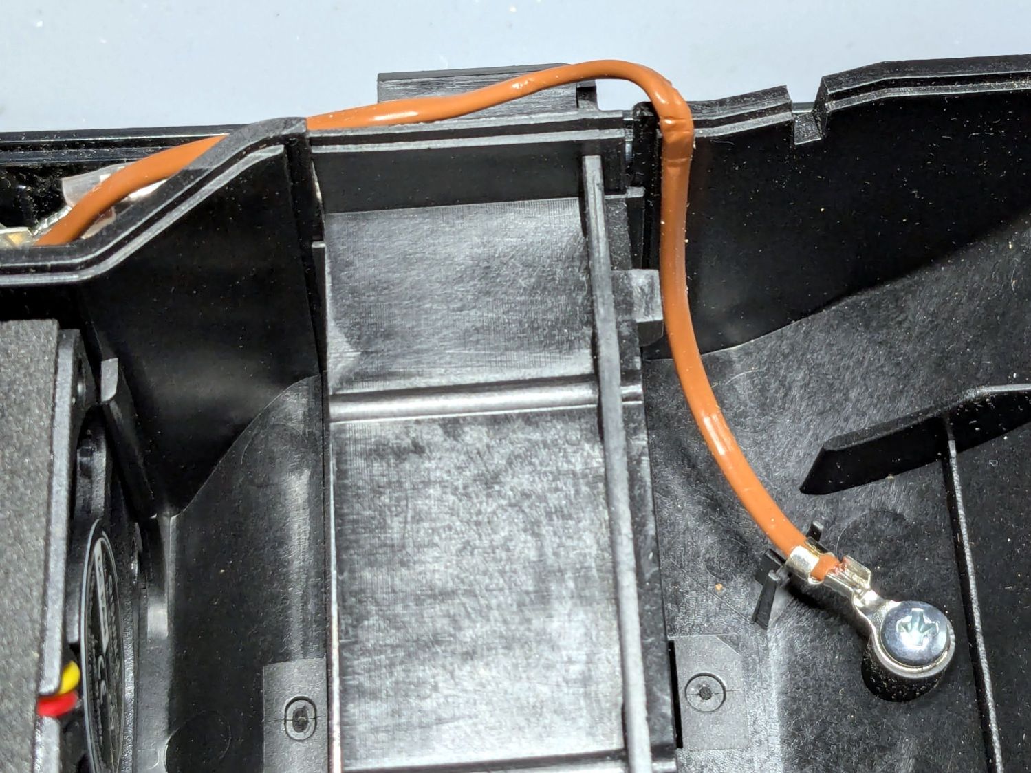
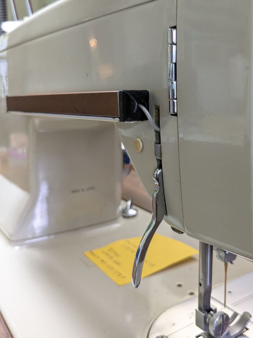
The rear light bar wire once again burrows into the machine above the presser foot lever:
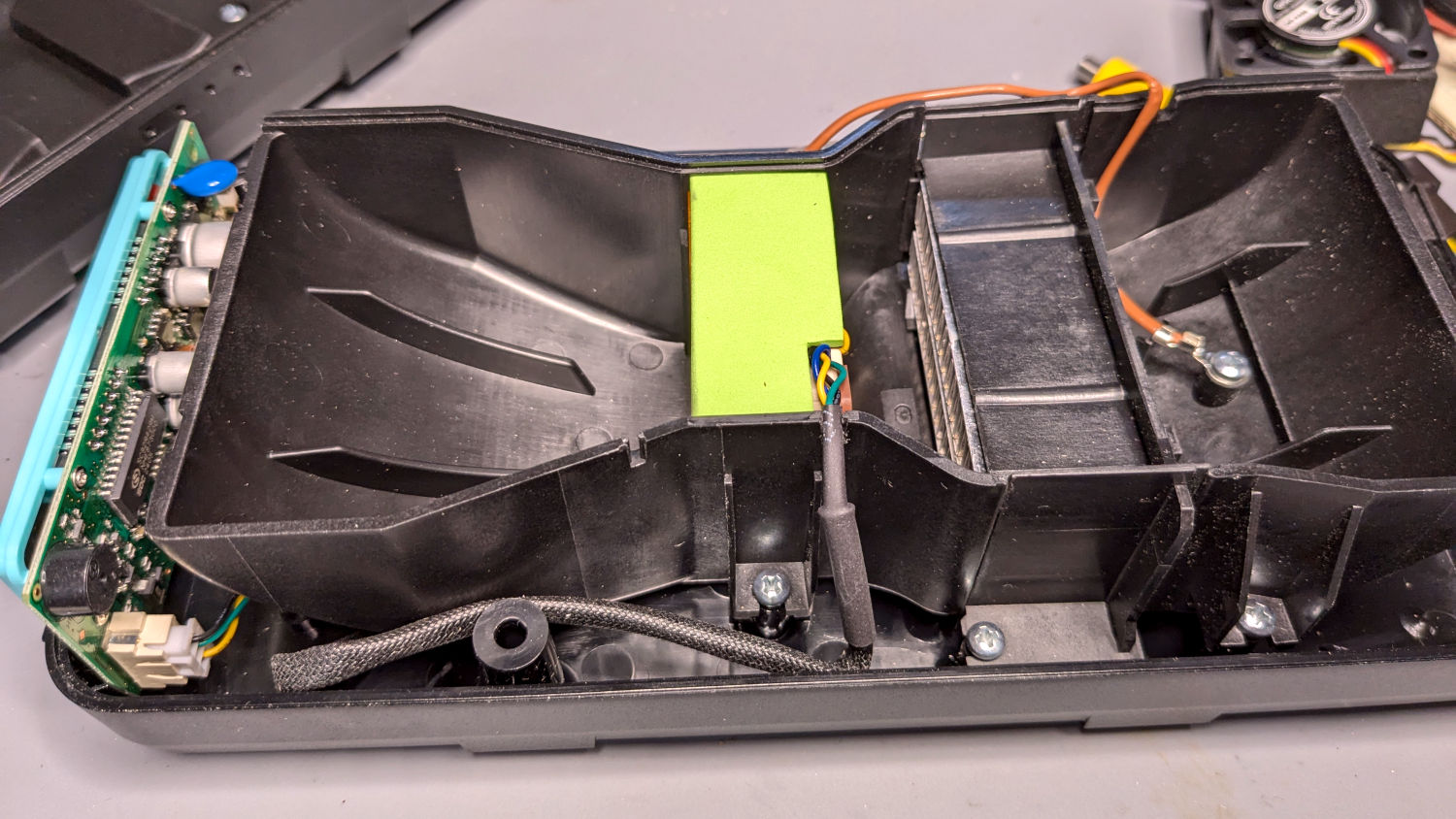
All the LED wiring fans out through the endcap:
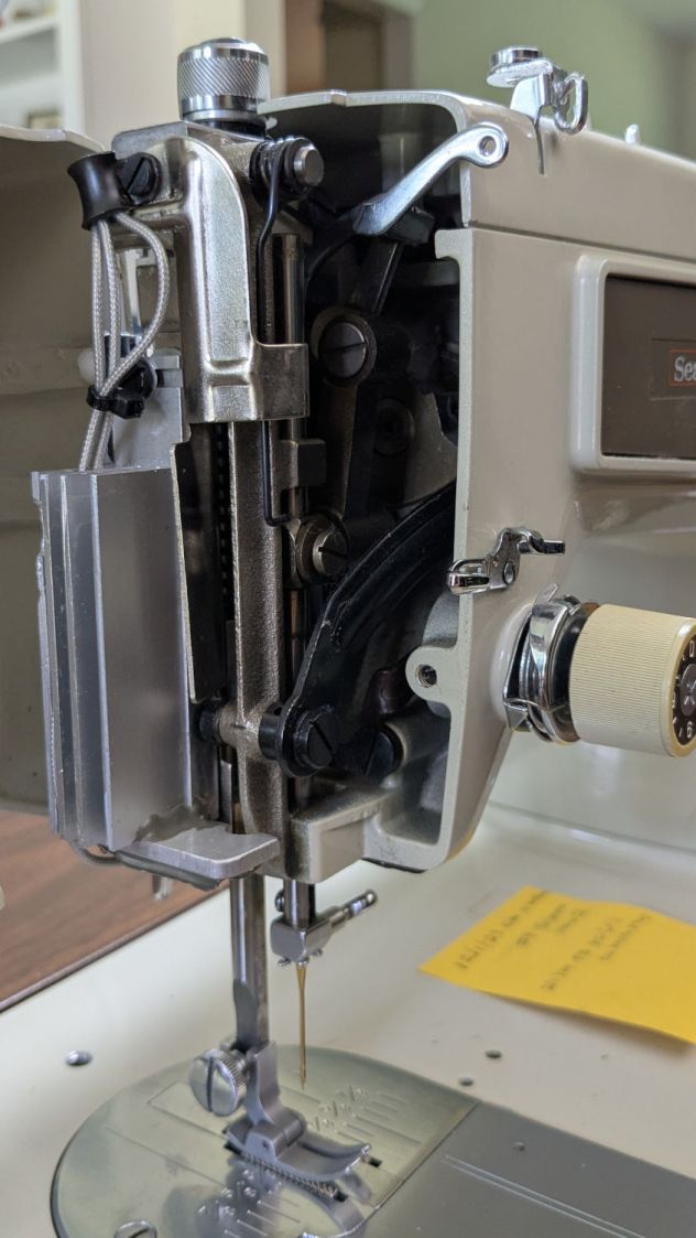
You can just barely see the edge of the strip of LEDs epoxied to the bottom of the machine nose, on the right of the needle.
If I were inclined to rebuild the needle LEDs, I’d use flexy silicone wiring instead of the Teflon insulated coax. The black insulation wouldn’t be nearly as pretty, but it’d be *way* easier to cut to length and solder.
The patient survived the operation and sewing should resume shortly …