The Smell of Molten Projects in the Morning

Ed Nisley's Blog: Shop notes, electronics, firmware, machinery, 3D printing, laser cuttery, and curiosities. Contents: 100% human thinking, 0% AI slop.

Category: Electronics Workbench

Electrical & Electronic gadgets

  • Enover Outlet Timer: Over-powered Zener Diode

    Enover Outlet Timer: Over-powered Zener Diode

    This being the season of lights, I deployed some outlet timers to turn them on at dusk and off at bedtime. The timers spend much of the rest of their lives plugged into outlets in the Basement Laboratory to keep their internal NiMH backup batteries charged, although they’re not controlling anything:

    Enover outlet timer - overview
    Enover outlet timer – overview

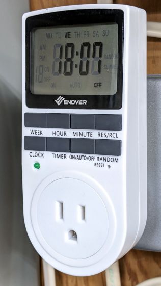
    This one is labeled ENOVER, but it’s essentially identical to all the others sporting random alphabetic names; I have a few more labeled UKOKE in the same plastic case. The current crop uses a different case and has one fewer button, but don’t expect any real difference.

    One of the timers had a blank display and didn’t respond to button pushes or a pin punch poked in the RESET hole, so I dismantled it to see what was inside.

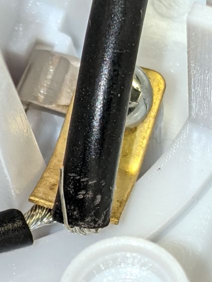
    Both the hot and neutral terminals had stray wire strands:

    Enover outlet timer - stray wire strand
    Enover outlet timer – stray wire strand

    The power board had the usual missing components, suggesting it had been cheapnified after passing whatever regulatory inspection it might have endured to get a CE mark on its dataplate:

    Enover outlet timer - power board - overview
    Enover outlet timer – power board – overview

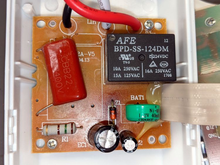
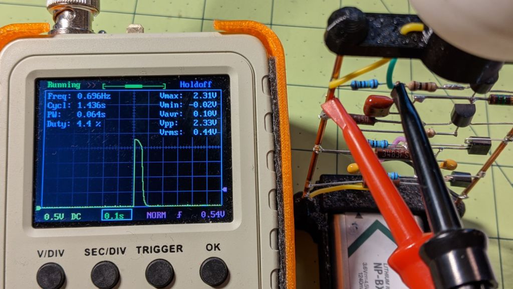
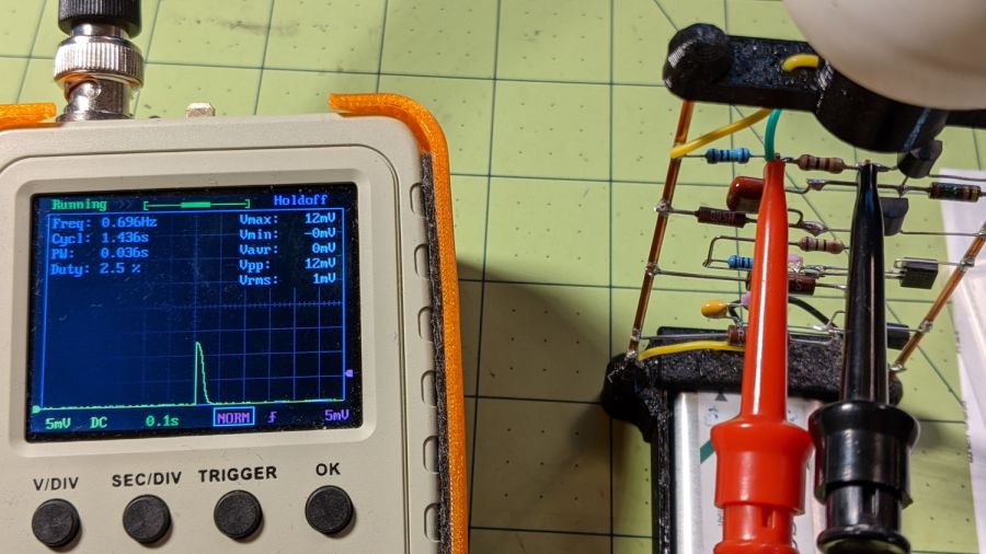
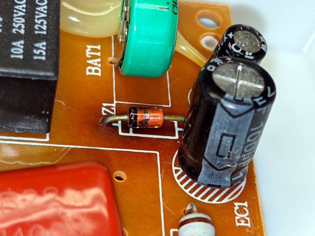
    The alert reader may have already noticed the mmmmm smoking gun:

    Enover outlet timer - scorched diode
    Enover outlet timer – scorched diode

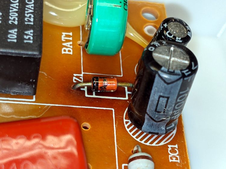
    Incredibly, Z1 has a part number wrapped around it! A quick lookup shows a 1N4749A is a 24 V 1 W Zener diode, neatly matching the 24 V relay. The datasheet gives a 10.5 mA test current and a 38 mA maximum regulator current, with a caveat: “Valid provided that electrodes at a distance of 10mm from case are kept at ambient temperature”

    The relay datasheet says 8.3 mA nominal coil current, a mere 200 mW, which is much easier to dissipate in wire wrapped around a steel core than in a little diode.

    Evidently the poor diode ran rather hot before becoming a dead short, because a phenolic PCB (definitely not at ambient temperature) ought not discolor like that.

    Indeed, measuring Z1 in another, still functional, Enover timer showed 25 V and a similarly discolored patch around Z1, suggesting the circuit design requires a bit more disspation from the diode than it can comfortably deliver.

    I replaced it with a 1N970B from the Basement Laboratory Warehouse, rated for only 0.5 W in a seemingly identical case, buttoned the whole thing up, and left it in the middle of the concrete basement floor overnight. It wasn’t smoking and continued working in the morning, so I defined things to be no worse than before and declared victory.

    Should when the next one fails the same way, I’ll epoxy a small heatsink to that poor diode and its leads to reduce its overall temperature.

    For future reference, the underside of the PCB shows a distinct lack of post-soldering flux cleanup:

    Enover outlet timer - power board - solder side
    Enover outlet timer – power board – solder side

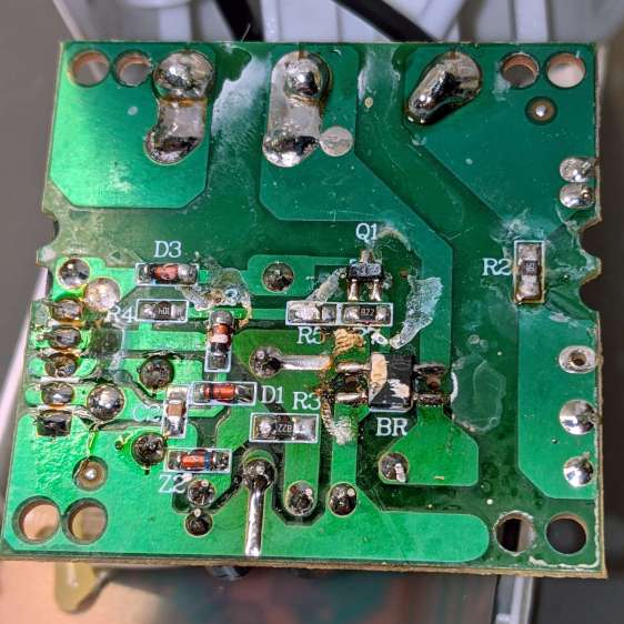
    I swabbed it with denatured alcohol, although doing so certainly didn’t make any change to its behavior.

    Memo to Self: no-clean flux is a thing.

    It’s worth noting no other components show signs of overheating, despite the diode becoming a short circuit, so R1 (a big power resistor) is most likely the shunt regulator’s dropping resistor and can survive the additional power.

    Should the diode fail open, the rest of the circuitry will be toast.

  • Astable Multivibrator: Amber LED

    Astable Multivibrator: Amber LED

    Adding an amber LED to the collection:

    Astable AA - Amber - overview
    Astable AA – Amber – overview

    Because a yellow / amber LED runs at a lower voltage than blue and green LEDs, it sits atop an astable multivibrator, rather than a discrete LM3909. The battery holder has a pair of carbon-zinc “Extra-Heavy Duty” AAA cells, so corrosion and leakage pose a foreseeable hazard.

    The voltage across the 100 Ω LED ballast indicates a 9 mA peak LED current, which is somewhat dim in ordinary room light:

    Astable AA - Amber - LED current 100 ohm
    Astable AA – Amber – LED current 100 ohm

    The corresponding LED voltage says the LED runs at 2.1 V for that much current:

    Astable AA - Amber - LED V
    Astable AA – Amber – LED V

    Something around 39 Ω should make it more visible.

  • Monthly Science: Batmax NP-BX1 Status

    Monthly Science: Batmax NP-BX1 Status

    After powering my Sony HDR-AS30V helmet camera for nearly all of this year’s riding, the Batmax NP-BX1 lithium batteries still have roughly 90% of their original capacity:

    Batmax NP-BX1 - 2020-11
    Batmax NP-BX1 – 2020-11

    Those are hot off the Official Batmax charger, which appears identical to other randomly named chargers available on Amazon.

    They’re holding up much better after a riding season than the DOT-01 batteries I used two years ago:

    Sony DOT-01 NP-BX1 - 2019-10-29
    Sony DOT-01 NP-BX1 – 2019-10-29

    Empirically, they power the camera for about 75 minutes, barely enough for our typical rides. I should top off the battery sitting in the camera unused for a few days, although that hasn’t happened yet.

    Of course, the Batmax NP-BX1 batteries I might order early next year for the new riding season have little relation to the ones you see here.

  • Astable Multivibrator: Dressed-up LED Spider

    Astable Multivibrator: Dressed-up LED Spider

    Adding a bit of trim to the bottom of the LED spider makes it look better and helps keep the strut wires in place:

    Astable Multivibrator - Alkaline - Radome trim
    Astable Multivibrator – Alkaline – Radome trim

    It’s obviously impossible to build like that, so it’s split across the middle of the strut:

    Astable Multivibrator - Alkaline - Radome trim
    Astable Multivibrator – Alkaline – Radome trim

    Glue it together with black adhesive and a couple of clamps:

    LED Spider - glue clamping
    LED Spider – glue clamping

    The aluminum fixtures (jigs?) are epoxied around snippets of strut wire aligning the spider parts:

    LED Spider - gluing fixture
    LED Spider – gluing fixture

    Those grossly oversized holes came pre-drilled in an otherwise suitable aluminum rod from the Little Tray o’ Cutoffs. I faced off the ends, chopped the rod in two, recessed the new ends, and declared victory. Might need better ones at some point, but they’ll do for now.

    Next step: wire up an astable with a yellow LED to go with the green and blue boosted LEDs.

  • Atreus Keyboard: LED Thoughts

    Atreus Keyboard: LED Thoughts

    Having helped grossly over-fund the Atreus Kickstarter earlier this year, a small box arrived pretty much on-time:

    Atreus keyboard - overview
    Atreus keyboard – overview

    I did get the blank keycap set, but have yet to screw up sufficient courage to install them. The caps sit atop the stock Kailh (pronounced, I think, kale) BOX Brown soft tactile switches; they’re clicky, yet not offensively loud.

    Removing a dozen screws lets you take it apart, revealing all the electronics on the underside of the PCB:

    Atreus keyboard - PCB overview
    Atreus keyboard – PCB overview

    The central section holds most of the active ingredients:

    Atreus keyboard - USB 32U4 Reset - detail
    Atreus keyboard – USB 32U4 Reset – detail

    The Atmel MEGA32U4 microcontroller runs a slightly customized version of QMK:

    Atreus keyboard - 32U4 - detail
    Atreus keyboard – 32U4 – detail

    Of interest is the JTAG header at the front center of the PCB:

    Atreus keyboard - JTAG header
    Atreus keyboard – JTAG header

    I have yet to delve into the code, but I think those signals aren’t involved with the key matrix and one might be available to drive an addressable RGB LED.

    For future reference, they’re tucked into the lower left corner of the chip (the mauled format comes from the original PDF):

    Atmel 32U4 - JTAG pins
    Atmel 32U4 – JTAG pins

    The alternate functions:

    • SCK = PB1
    • MOSI = PB2
    • MISO = PB3

    I don’t need exotic lighting, but indicating which key layer is active would be helpful.

    Love the key feel, even though I still haven’t hit the B key more than 25% of the time.

  • MOSFET Astable: NP-BX1 Rundown

    MOSFET Astable: NP-BX1 Rundown

    After eight months from a full charge, an old NP-BX1 lithium battery has come to this:

    Astable green - NP-BX1 - 2.31 V
    Astable green – NP-BX1 – 2.31 V

    The astable still ticks along at 1.4 seconds per blink, but the green LED barely lights up from a 2.1 V battery:

    Astable green - NP-BX1 - 12 mV 100 ohm
    Astable green – NP-BX1 – 12 mV 100 ohm

    A pulse of 12 mV across the 100 Ω resistor puts the LED current at a mere 120 µA: no wonder the poor thing wasn’t visible in ordinary room light.

    Another full charge restored its vigor for another couple of seasons.

  • Mini-lathe DRO Battery Lifetime

    Mini-lathe DRO Battery Lifetime

    It seems 390/389 alkaline button cells can power the mini-lathe’s DROs for about a year:

    Mini-lathe DRO battery replacement - 11 months
    Mini-lathe DRO battery replacement – 11 months

    Given that the replacement cells all come from the same batch, they’re aging on the shelf as well as in the DROs.

    Once again, I replaced both of them.