Ed Nisley's Blog: Shop notes, electronics, firmware, machinery, 3D printing, laser cuttery, and curiosities. Contents: 100% human thinking, 0% AI slop.
The Sony HDR-AX30V helmet camera puts far more demands on its battery than the Planet Bike Superflash:
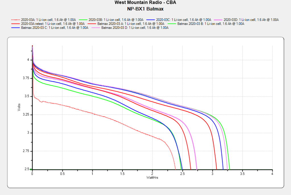
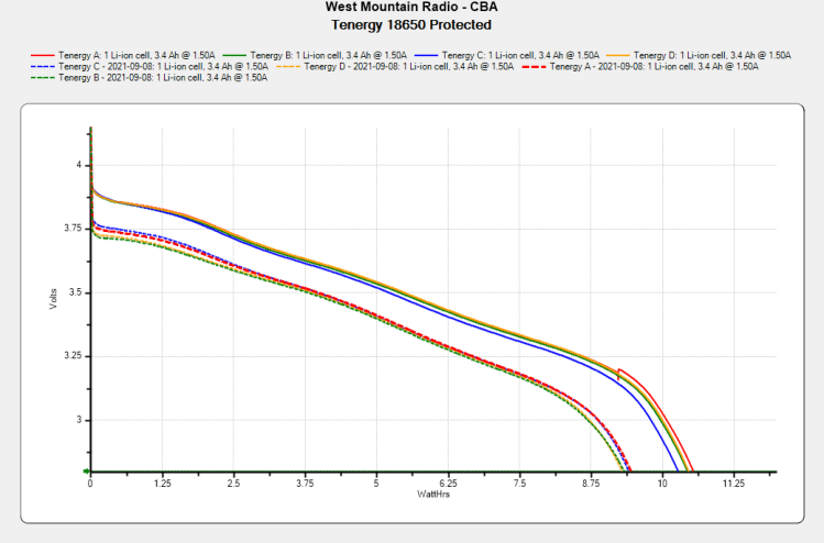
Batmax NP-BX1 – 2021-09 vs 2020-03
The four traces on the right show the BatMax NP-BX1 lithium batteries (cells, really) originally stored about 3 W·h when they arrived in March 2020. The four solid traces to their left show the capacity dropped to a little over 2 W·h after two riding seasons. Batteries B and C started out above average and are now below, for whatever that means.
The red dotted trace shows the effect of not using the NP-BX1 test holder for that length of time; those homebrew contact pins apparently needed some exercise.
Having replaced the Planet Bike Superflash on Mary’s Tour Easy with a 1 W red LED, testing the eight Panasonic Eneloop AAA cells that have been powering it (and the one on my bike) for the last four years seemed useful:
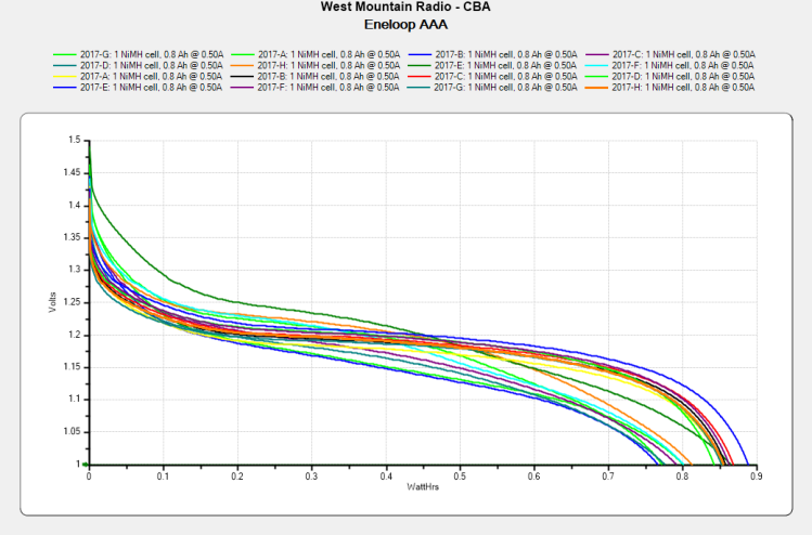
Panasonic Eneloop AAA – 2021-09 vs 2017-04
The sheaf of curves over on the right came from the first full charge, with the untidy collection below them show the current state after a full charge. This is at an unreasonably high 500 mA discharge.
The overall capacity has dropped by 10%, which isn’t all that bad, but the 10% voltage reduction toward the end of the curves is a Bad Thing for an LED flasher intended to run from 1.5 V alkaline cells. In practice, I recharge the batteries once a week while they are still going strong, but the difference between alkalines and NiMH cells is obvious even at full charge.
Now I can run four pairs through the agingSuperflash on my bike …
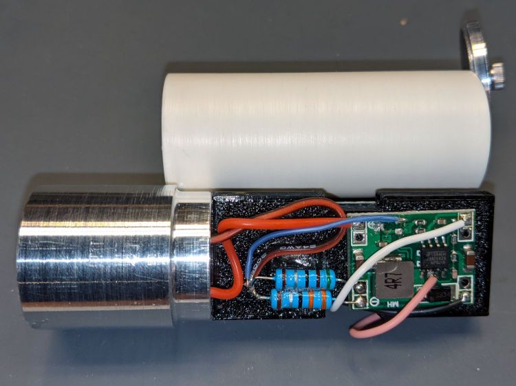
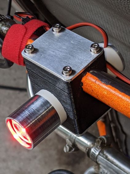
There’s just enough slack in the LED wiring to clip a Tek current probe in there:
Tour Easy Rear Running Light – regulator wiring
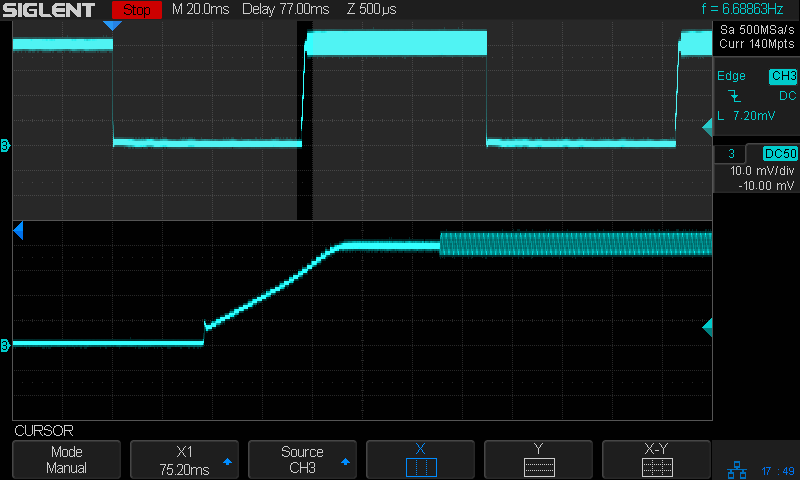
Which reveals the LED current waveform:
Red LED – LED current – 100 mA-div
The LED is on continuously, except for the two 75 ms Morse code dits in the upper trace.
The lower trace shows the current ramping up at the end of the first dit, from zero to 400 mA in 1.5 ms.
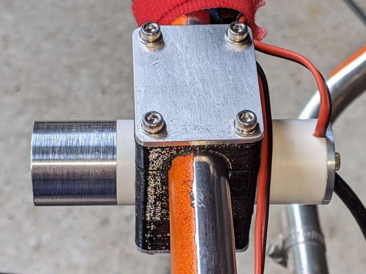
Clamping the probe around the 6.3 V power supply lead:
Red LED – power supply – 100 mA-div
The supply current includes maybe 20 mA for the Arduino running the Morse code program and the current ramps up from there to about 250 mA when the LED is on.
The LED drops 2.6 V at 400 mA, so it dissipates a smidge over 1 W. The 2.0 Ω current sense resistor (3.3 Ω in parallel with 5.1 Ω) dissipates 800 mV × 400 mA = 320 mW.
The dissipation from the Bafang headlight output, including the Arduino, is 1.6 W.
The running light ticks along at the hot side of comfortably warm on the Electronics Workbench and runs barely warm in free air out on the bike, so I’ll define it to be Good Enough™.
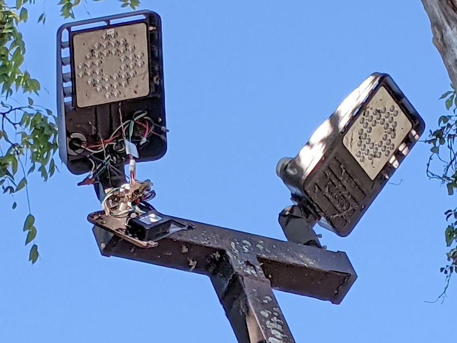
It’s hard to be sure, but I think there’s a paper wasp nest around the bundle of wires just above the transformer / ballast / whatever. Perhaps the repair tech departed with the job unfinished?
As with traffic signals, flashlights, and automotive lighting, the LEDs surely work long after the driver circuitry has given up.
The overall capacity is down by 10%, with the voltage depressed by 120 mV over most of the curve.
Although I don’t keep daily records, the back of the envelope reveals 150 to 200 hour-long rides per year during the last four years, so call it 700 charging cycles:
Anker LC40 Flashlight – Anodizing fade
High brightness draws 1.5 A and low is 50% duty cycle, so a typical ride requires 750 mA·h = 2.5 W·h. Each cell lives for three or four rides with the LED set to low brightness and the numbers work out close enough.
Level 9 must be 100% of the maximum motor current so the throttle can apply full power to get out of the way in a hurry.
The new and even more derated configuration allows small-step assist level selection for our usual riding, at the cost of an unused huge step to level 9 for the throttle:
The LC=18 line limits the maximum motor current to 18 A, rather than the rated 24 A, which may improve controller MOSFET longevity; reliable evidence is hard to come by. Controller failures seem to happen more often to riders who value jackrabbit acceleration on harsh terrain, so it may make little difference for road cyclists.
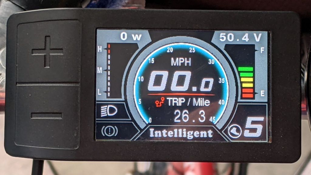
So level 5 now selects 75% × 20% = 15% of the motor’s nominal 750 W:
Tour Easy Bafang – display 26 mi
Call it 115 W: we’re both getting plenty of exercise!