Ed Nisley's Blog: Shop notes, electronics, firmware, machinery, 3D printing, laser cuttery, and curiosities. Contents: 100% human thinking, 0% AI slop.
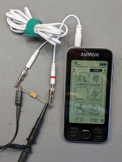
Being that type of guy, I had to look at the electricity. Somewhat to my surprise, the reference load turns out to be a pure 500 Ω resistance, which is easy enough to cobble up from a pair of 1 kΩ resistors:
Auvon AS8016 – test setup
The alligator clips crunched around the 2 mm pins are not appropriate for even a brutal e-stim session; they’re from the Small Drawer of Test Connectors, to which they shall return unblooded.
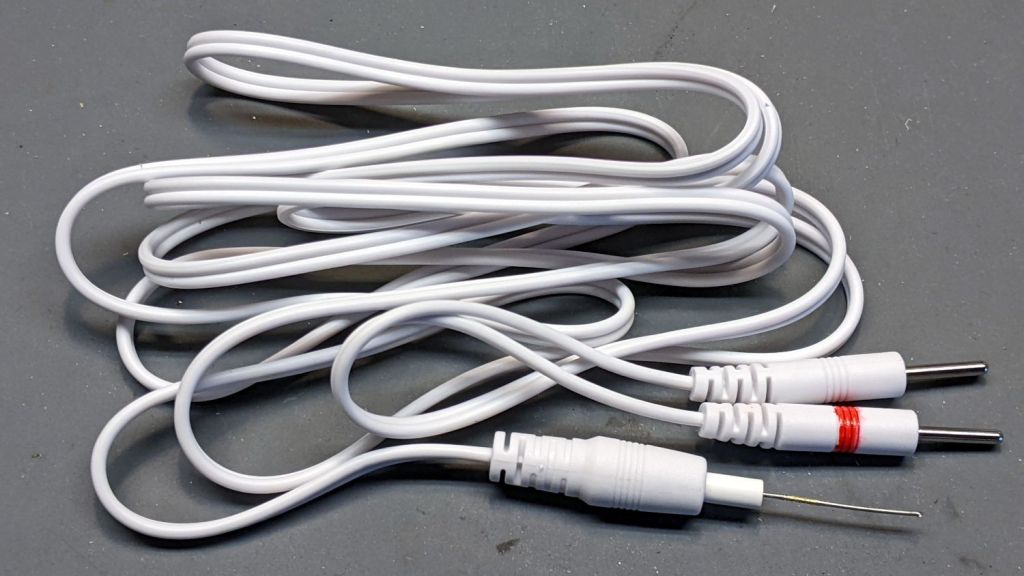
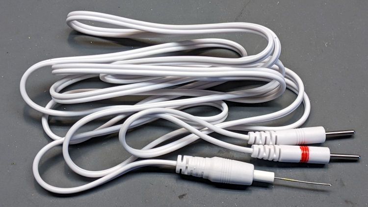
The red Sharpie highlight around one pin identifies the center conductor of the two-wire cable, as determined by simple continuity testing:
Auvon AS8016 – marked cable
The 22 mil = 0.5 mm wire (from the Little Tin o’ Snippets) fits snugly into the coaxial connector’s center contact; one could probably slip a rounded shim between the shell and the outer contact, perhaps to debug an intermittent connection. Note that the connectors on both ends of the wires are notstandardized among various TENS/EMS manufacturers.
The A1 and A2 jacks are wired in parallel, as are the B1 and B2 jacks, with the A pair galvanically isolated from the B pair. You can set the modes / programs / pulse parameters differently for A and B. Although the manual doesn’t mention it, using the A and B channels (perhaps with the same settings) prevents a galvanic connection (and thus any current) from flowing between the A and B electrodes; this seems important for electrode pairs placed on opposite sides of your body to prevent current through your heart.
The pulses have no DC component, so the actual wire polarity doesn’t really matter, but a foolish consistency definitely simplifies going back to re-measure things. Subsequent waveforms show the voltage with respect to the unmarked (outer) conductor.
Suppressing the DC bias prevents ionic migration between / under the electrode pads. The classic RC-equivalent output circuit uses a series capacitor, resulting in an asymmetric pulse waveform with zero net DC voltage:
Capacitor Coupled Pulse
There’s no DC path between the center and outer conductors, but in this day and age the circuitry could be a completely isolated bipolar FET driver:
Auvon M01 Pulse
With all that sorted out, I can make measurements!
Subject: [redacted] review blog invitation about bluetooth programmer
Message: Hi dear,
Thanks for taking time to read this email.
I am Colleen from [redacted] brand, we sell two way radio on Amazon. I learned that you have wrote two way radio review blog before and I think your blog was written well.
Now we have a product named bluetooth programmer that need to be reviewed. […] We would like to invite you to write a review blog about it.
Your can earn $2 from each product sold! We promise it. Just put the link we provided you in your blog and the Amazon backstage will count the data. And we will pay you $2 for per product sold by your link through PayPal on the 30th of every month. (Please provide your PayPal account)
If you are willing to help us write a blog, please tell us if you have a radio and your address we will send you the product for free to review.
You can view more detailed information through this link:
Most likely, it’s just the result of an ordinary web search.
You might think everybody would know about Amazon’s crackdown on out-of-band review kickback scams, but either word hasn’t gotten around or the rewards still exceed the penalties. I think the latter applies, particularly when the offender (or its parent company) can spin up another randomly named Amazon seller with no loss of continuity.
“Earning” two bucks on a few purchases during the course of a year won’t move my Quality of Life needle, so I reported them to Amazon and that might be that.
Speaking of randomly named sellers, it’s highly likely any Brand Name you remember from the Good Old Days has been disconnected from the tool / hardware / service you remember. Perusing a snapshot of the who-owns-who tool landscape as of a few years ago may be edifying: I didn’t know Fluke and Tektronix now have the same corporate parent.
Enjoy unwrapping your presents and playing with your toys …
A lithium battery management system can (and should!) disable the battery output to prevent damage from overcurrent or undervoltage, after which it must be reset. The inadvertent charge port short may have damaged the BMS PCB, but did not shut down the battery’s motor output, which means the BMS will not should not require resetting. However, because all this will happen remotely, it pays to be prepared.
For this battery, the positive terminal is on the right, as shown by the molded legend and verified by measurement.
A doodle with various dimensions, most of which are pretty close:
Bafang battery – connector dimension doodle
Further doodling produced a BMS reset adapter keyed to fit the battery connector in only one way:
Bafang battery – adapter doodle
Which turned into the rectangular lump at the top of the tool kit, along with the various shell drills and suchlike discussed earlier:
Bafang battery tools
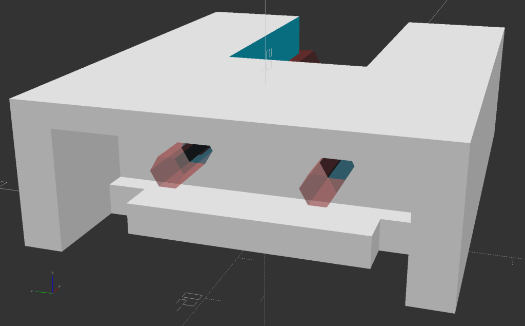
Looking into the solid model from the battery connector shows the notches and projections that prevent it from making incorrect contact:
Battery Reset Adapter – show front
The pin dimensions on the right, along with a mysterious doodle that must have meant something at the time :
Bafang battery – adapter pin doodle
The pins emerged from 3/16 inch brass rod, with pockets for the soldered wires:
Bafang battery – reset tool – pins
The wires go into a coaxial breakout connector that’s hot-melt glued into the recess. The coaxial connectors are rated for 12 V and intended for CCTV cameras, LED strings, and suchlike, but I think they’re good for momentary use at 48 V with minimal current.
I printed the block with the battery connector end on top for the best dimensional accuracy and the other end of the pin holes held in place by a single layer of filament bridging the rectangular opening:
Bafang battery – reset tool – hole support layer
I made a hollow punch to cut the bridge filaments:
Bafang battery – reset tool – pin hole punch
The holes extend along the rectangular cutout for the coaxial connector, so pressing the punch against the notch lines it up neatly with the hole:
Bafang battery – reset tool – hole punching
Whereupon a sharp rap with a hammer clears the hole:
Bafang battery – reset tool – hole cleared
A dollop of urethane adhesive followed the pins into their holes to lock them in place. I plugged the block and pins into the battery to align the pins as the adhesive cured, with the wire ends carefully taped apart.
After curing: unplug the adapter, screw wires into coaxial connector, slobber hot melt glue into the recess, squish into place, align, dribble more glue into all the gaps and over the screw terminals, then declare victory.
It may never be needed, but that’s fine with me.
[Update: A few more doodles with better dimensions and fewer malfeatures appeared from the back of the bench.]
This file contains hidden or bidirectional Unicode text that may be interpreted or compiled differently than what appears below. To review, open the file in an editor that reveals hidden Unicode characters.
Learn more about bidirectional Unicode characters
Short-circuiting the Bafang battery’s charge port may have done anything from completely destroying the battery management circuit to just welding a brass nugget onto the port’s center pin. The main output to the bike motor remained functional, so my friend used it on rides over the next few days to reduce the charge level.
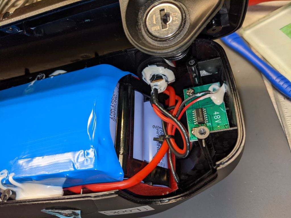
Meanwhile, I peeked inside the undamaged battery on Mary’s bike:
Bafang battery interior – overview
The battery pack is neatly shrink-wrapped and firmly glued into the plastic shell, with the battery management PCB on the other side of the battery. Some gentle prying suggests it will be difficult to disengage the adhesive, so getting the pack out will likely require cutting the blue wrap, extricating the cells as an unbound set, then cutting the blue wrap to release the wires.
A closer look at the nose of the battery:
Bafang battery interior – front
The large red wire entering on the left comes from the motor connector, loops around the nose of the battery, and probably connects to the battery’s most positive terminal or, perhaps, to the corresponding BMS terminal.
The medium black wire from the side contact of the coaxial jack (atop the pair of red wires) burrows under the battery and likely connects to the most negative battery terminal. This is the charger plug’s outer terminal.
The small red wire from the center contact of the coaxial jack (between the medium black and red wires) goes to the charge indicator PCB in the nose of the battery. This is basically a push-to-test voltmeter with four LEDs indicating the charge state from about 40 V through 54 V. The small black wire from that PCB burrows under the battery on its way to the BMS.
The medium red wire from the center contact goes to the BMS.
There is no way to determine how much damage the short might have done, although the silicone-insulated wires should have survived momentary heating, unlike cheap PVC insulation that slags down at the slightest provocation.
Removing and replacing the coaxial jack requires Cutting Three Wires then rejoining them, a process fraught with peril. You must already have a profound respect for high voltages, high currents, and high power wiring; this is no place for on-the-job learning and definitely not where you can move fast and break things.
With this in mind, the only hope is to remove the nugget and see if the battery charges properly.
The trick will be to do this without any possibility of shorting a metallic tool between the center pin and the side contact.
The lock might deter casual thievery, but really prevents the battery from bouncing out of its mounting plate while riding.
The right side has a charge port closed with a rubber plug:
Bafang battery – charge port – closed
The cover protects a coaxial jack with a 5.5 mm OD and a 2.1 mm center pin:
Bafang battery – charge port
My friend in Raleigh generally removes the battery before hoisting the bike into the back of her car to haul it to a friend’s house for their companionable rides: not lifting an additional seven pounds is a Good Idea™.
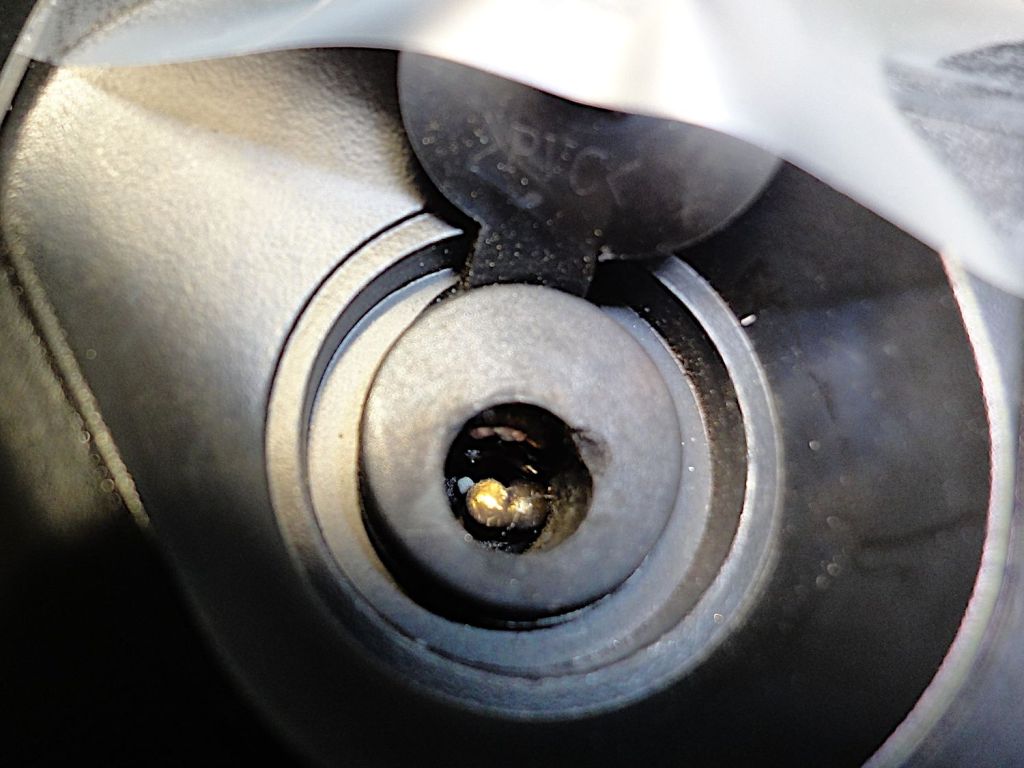
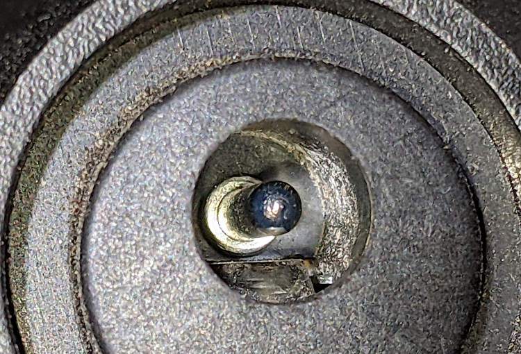
A momentary distraction in the middle of that process caused her to insert the brass key into the charging port, rather than the lock. The key put a very short circuit between the coaxial jack’s side contact and the center pin, melting the key tip and welding a brass nugget onto the side of the pin:
Bafang battery – damaged charge port
The charger plug normally sits almost flush to the port’s surface:
Bafang battery – charge plug
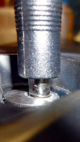
The nugget keeps the plug out the damaged port, preventing the plug from making electrical contact:
Bafang battery – damaged port – plug
She owned the problem and immediately bought another battery, which tells you the value she places on riding her e-bike.
Verily it is written: let someone who is without whoopsie cast the first shade.
Any takers? Yeah, the way I see it, someone who says they’ve never done anything quite like that is either not doing anything or not telling the complete truth. For sure, I’ve done plenty of inadvertent damage!
Here’s the problem:
The damaged battery is the better part of 600 miles away from my shop
Civilians cannot ship 560 W·hr lithium batteries through any parcel delivery service
Civilians cannot fly or take the train with such a battery, either
Driving 1200 miles twice is out of the question for either of us
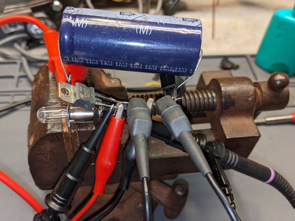
Dropping the ordinary flashlight bulb into the drawer where it belonged revealed what I think is a halogen flashlight bulb, so I rebuilt the blinky test setup:
Halogen flashlight bulb test setup
This time I used a BUZ71A MOSFET (13 A, 100 mΩ RDS) driven with a 10 V gate pulse to make sure it acted like a switch instead of a current sink.
The first attempt looked … odd:
Halogen 3V – no cap – 4ms 1A-div
The gate pulse is yellow, the drain voltage is magenta, the bulb current is cyan at 1 A/div, and the timebase ticks along at 2 ms/div.
Moving the magenta trace to the supply voltage on the other side of the bulb produces even more weirdness:
Halogen 3V – no cap – Vsupply – 4ms 1A-div
Apparently, slugging a 3 A bench supply with a 3 A pulse lasting only 4 ms causes distress of the output tract.
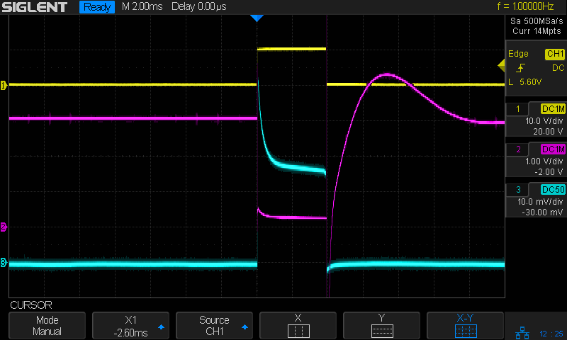
Kludging a hulking 22 mF (yes, 22000 µF) cap across the power supply provides enough local storage to make things work properly:
Halogen 3V – 22000µF – Vsupply – 4ms 1A-div
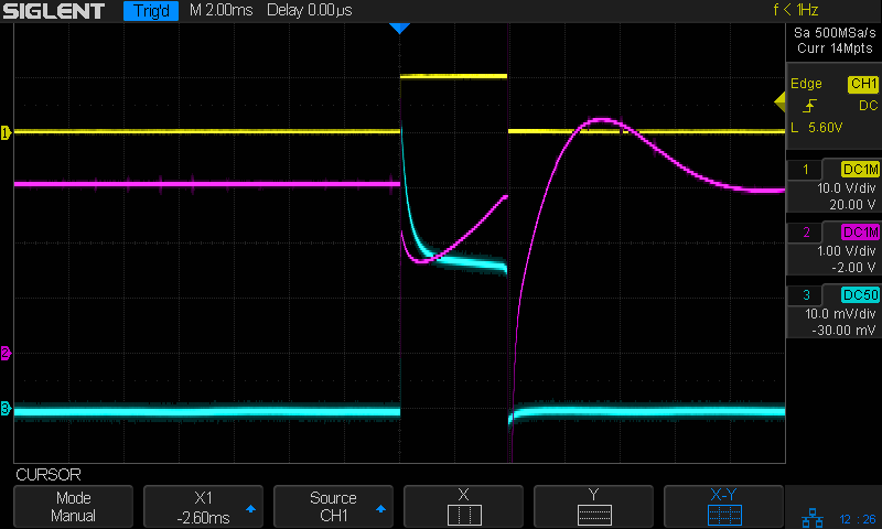
With the cap in place, the drain terminal looks less unruly:
Halogen 3V – 4ms 1A-div
The drain voltage starts at about 600 mV with the 3 A pulse, a bit more than you’d expect from the alleged 100 mΩ drain-source resistance, but those numbers are generally aspirational and the test setup leaves a lot to be desired.
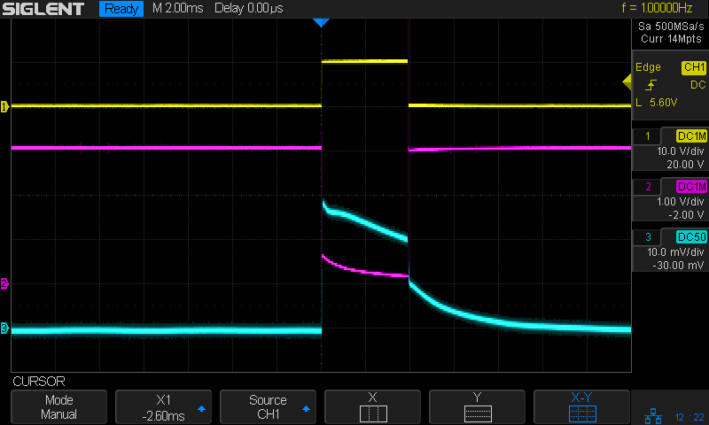
A 10 ms pulse produces a distinct flash, rather than a dull orange blip (timebase now at 10 ms/div):
Halogen 3V – 22000µF – 10ms 1A-div
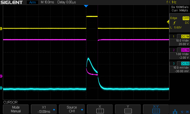
A 30 ms pulse reaches full brightness as the filament settles at normal operating temperature:
Halogen 3V – 22000µF – 30ms 1A-div
A 20 ms flash might suffice for decorative purposes, in which case each pulse requires 90 mW·s = 3 V × 1.5 A × 20 ms of energy. Running it all day requires 7.8 kW·s = 2.2 W·h, so it’s even less appealing than that old skool tungsten bulb.
Which is, of course, why LED flashlight bulbs are a thing.
A flashlight bulb emerged from the clutter, which prompted me to ask if it might make an interesting blinky. Spoiler: probably not.
The bulb had “2.4 V 0.7 A” stamped on its shell, so the test setup looked like this:
Flashlight bulb test setup
A list seems helpful:
Solder wires to bulb in lieu of a socket
Bench supply at 2.4 V
Grossly abused 2N3904 NPN transistor as a switch
Function generator pulsing the base
Scope voltage probes on base (yellow) and collector (magenta)
Tek current probe on bench supply lead (cyan, 500 mA/div)
The function generator has a 50 Ω output, so depend on it to limit the base current just like it was a resistor. The output voltage is symmetric around 0 V, so apply an offset of half the peak-to-peak signal to get a positive-going pulse:
Flashlight bulb test – function gen setup
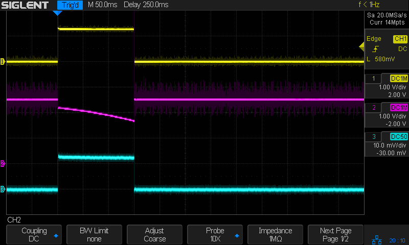
A 150 ms pulse gives the bulb just barely enough energy to light as a little orange blip, with the collector voltage dropping as the filament heats up and its resistance increases:
Tungsten 2.4V 700mA – 150ms
Given 350 ms to heat up, the bulb produces a nice white-hot flash:
Tungsten 2.4V 700mA – 350ms
The poor transistor acts as a 600 mA constant current sink, which isn’t surprising given its 300 mA absolute maximum current rating.
Homework: figure the base drive and current gain
Protip: don’t do that to a cherished transistor
The bulb resistance starts out at 0.5 Ω and rises to 2.5 Ω when the filament glows white-hot at the end of the pulse.
Something like 250 ms produces a noticeable blink, requiring 360 mW·s = 2.4 V × 600 mA × 250 ms from the power supply. Blinking once every ten seconds all day means 8640 pulses for a total energy of 864 mW·hr; call it 1 W·hr.
A pair of (fresh) AA alkaline cells provide 7.5 W·hr for maybe a week of blinkiness.
A not-dead-yet 18650 lithium cell might offer 15 W·hr, but running the bulb from 3.7-ish V, rather than 3-ish V, increases the energy per pulse by 20% and decreases the run time correspondingly.