Ed Nisley's Blog: Shop notes, electronics, firmware, machinery, 3D printing, laser cuttery, and curiosities. Contents: 100% human thinking, 0% AI slop.
A long-forgotten toy emerged from the heap bearing a trio of corroded NiMH cells between the usual plated-steel contacts:
Corroded contacts – original
The toy wasn’t worth salvaging, but I extracted the contacts and applied Evapo-Rust to see what happened. After an overnight soak, some corrosion remained:
Corroded contacts – after Evapo-Rust
Scrubbing with a stainless-steel detail brush removed the flakes and left reasonably clean metal behind:
Corroded contacts – after brushing
Although it’s not beautiful, I think the contacts came out as well as one could expect. The longer contact plate has holes, thinned sections, and some corrosion inside the spring; I’d be mildly tempted to rebuilt the whole thing with some nickel shim stock and a new spring.
If I were salvaging the toy, I’d dab vinegar on the wiring to neutralize the creeping potassium hydroxide, rinse the whole thing with water, and clean out the case. Instead, it joined the consumer electronics recycling box with a thud…
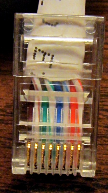
Yeah, the blue-stripe and green-stripe wires should be interchanged. Turns out the Link indicators on both ends lit up just fine, but no bits made it across the wire. Took quite a while to figure that one out, alas.
Turns out I was moving that router upstairs to get a better signal for folks out in the driveway and snaking the cable through the only suitable (i.e., existing) hole in the floor required cutting the molded-in-place connector off, then crimping a new one on. Both you and I know those wires must cross, but in the excitement of pushing all those wires into the connector, well … so it goes.
A useful explanation, including crossover and POE cable arrangements, lives there.
I did wrap silicone tape around the cable and connector butt for strain relief.
Memo to Self: just verifying the colors on the existing cable sometimes isn’t good enough!
I picked up a Lenovo headset on sale and over the course of a few weeks the mic boom pivot worked itself loose, until I finally dismantled the left ear cup to see what was inside. Come to find out that the mic boom has a molded threaded section held into the cup with a simple nut and no locking mechanism at all:
Lenovo headset – OEM mic boom pivot nut
I think the metal washer was intended as a low-friction pivot atop the compliant silicone (?) washer underneath, but the net effect was that the nut unscrewed a little bit more every time the mic boom moved. By the time I got in there, the nut was completely off the threads.
The original nut left a thread or two showing, so I found a thicker replacement nut with a better grip. The obvious solution involves a dab of Loctite to jam the nut in position, but we all know that some plastics, most notably acrylic, react badly to threadlocker and tend to disintegrate. Although I considered just epoxying the nut in place, that seems so, well, permanent.
So I dutifully tested a dab of Loctite on an inconspicuous spot inside the ear cup, got no reaction at all, put a drop on the boom pivot threads, and reassembled everything:
Lenovo headset – replacement mic boom pivot nut
Alas, by the time I got back upstairs and hung the mic on the rack, the boom fell completely out of the earcup! Back in the Basement Laboratory, I dismantled the thing again and confronted this mess:
Lenovo headset- Acrylic plastic vs. threadlock
Huh. The ear cup isn’t made of the same plastic as the mic boom: one shrugs off threadlock, the other disintegrates.
That’s obvious in retrospect, eh?
The only threads that aren’t ruined lie completely within the ear cup frame, with just a stub sticking up around the wire. So I cleaned things up and did what I should have done originally: put a dab of epoxy inside the nut to bind the pivot firmly in place. A snippet of unshrunk heatshrink tubing around the wire provides a bit of strain relief:
Lenovo headset – boom pivot nut with epoxy
There’s no longer any space for the compliant washer in that stack, so we’ll see how long this lasts. The next repair will certainly venture far inside non-economical territory. I like the headphones, though.
Memo to Self: Check in an inconspicuous spot on the same material.
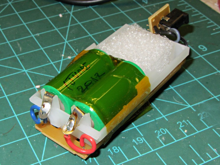
One of the battery packs I’d re-rebuilt failed in short order, which I wrote off to a bad cell and tossed it on the heap. Having recently found a small stack of Round Tuits, I’ve been cleaning off the bench and took the pack apart again. Turns out I blundered the solder joint between the positive cell terminal and the protective circuit board: the strap in the foreground joining those two points didn’t make a good connection to the cells.
That’s an awkward joint at best, because the protective circuit doesn’t come willingly out of the housing and you (well, I) must solder it without scorching the cells, the plastic case, or the PCB. It can be done, but it’s not easy.
Charged it up and it’s back in the A/B/C pack rotation again.
Memo to Self: Tough to find good repairmen these days, eh?
That circuit works pretty well for APRS tracking, I’d say, based on a 23 mile out-and-back ride over the Walkway:
KE4ZNU – Wouxun KG-UV3D – first ride
Had I gone further westward along Rt 299, however, the track would end: the bluffs on the east side of the Wallkill River Valley block much of the RF and Illinois Mountain (just to the west of Poughkeepsie) finishes the job. Evidently, nobody runs an APRS iGate or digipeater anywhere within sight of New Paltz…
FWIW, the Walkway’s hand-scrawled notice boards now entreat “Bicyclists: ride SLOW and YIELD to pedestrians.” OK, fair enough, but how about equal time: “WALKERS: keep RIGHT, remove earbuds, and PAY ATTENTION”. It’s amazing how four people can block nearly the entire width of a 25 foot path, then look startled after not hearing a bicycle bell that’s been dinging steadily for 15 seconds…
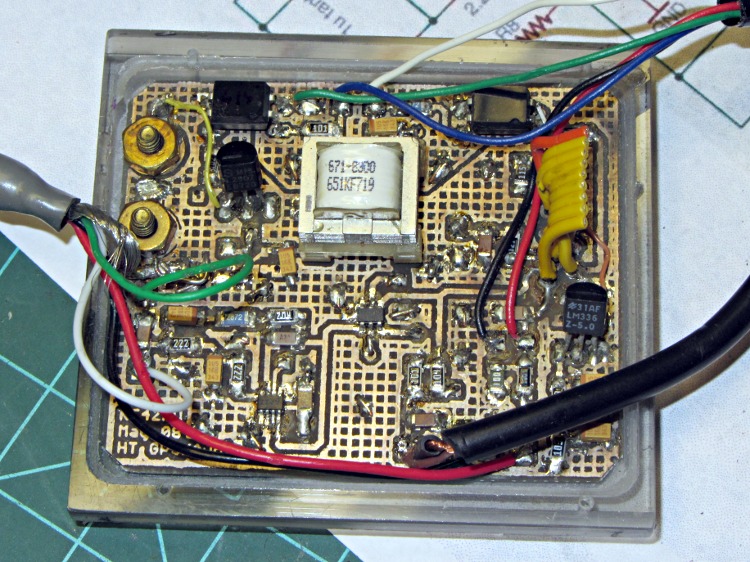
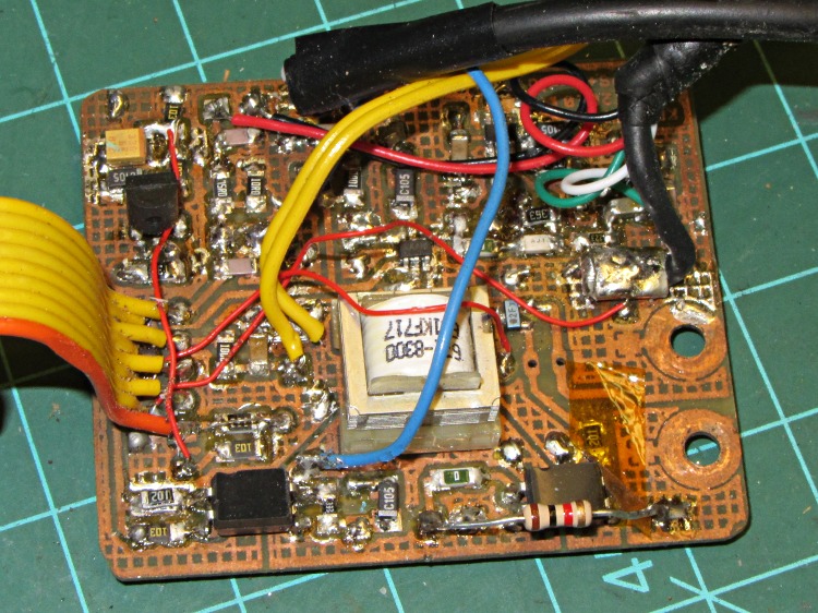
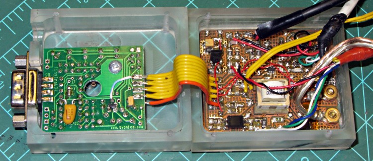
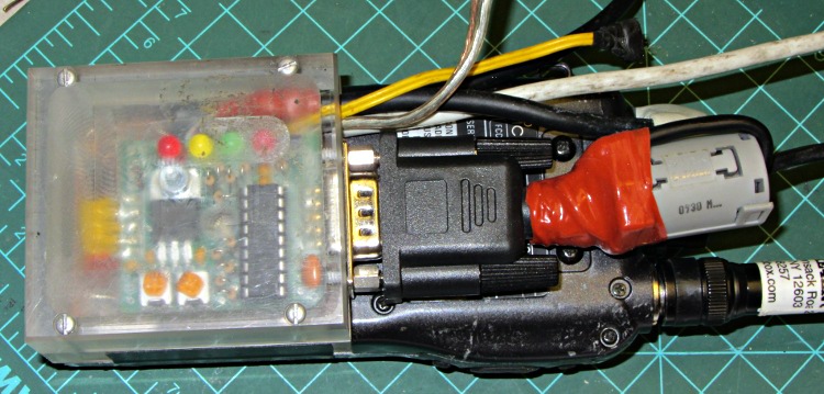
The robust wire I used for the external battery connection required a bit of diagonal cutter work to enlarge the hole in the top plate, but eventually everything fit together and the GPS interface box latched neatly onto the radio:
HT-GPS Case – cabled top view
The skein of cables:
Antenna: reverse SMA to UHF adapter = RG58 coax
GPS: TTL serial data from Byonics GPS2 receiver = DB-9 (OK, DE-9)
After a few rides to verify that this whole affair works, I must print up another case with slightly modified dimensions, add a plastic window over those cheerful LEDs on the TinyTrak3+ board, and mush an epoxy putty blob over the earphone and mic connections on that bright yellow plug plate. I’ve given up on the idea of having a cover for the top part of the battery compartment; there just isn’t enough space for such a thing and it’d be an impossibly delicate shell.
The radio seems happy enough being fed 9 V from a bench supply (to match the upconverted lithium packs I’ve been using on the bikes), rather than 7.4 V from its standard lithium pack. A freshly charged battery comes pretty close to 9 V, so they can’t be too fussy. It idles at about 100 mA, with periodic blips to 140 mA when (I think) the TinyTrak3+ tickles the GPS receiver, regardless of the supply voltage. Goosing it with 13.8 V surely wouldn’t have a happy outcome…
Lashed up like that on the bench, with the GPS receiver hanging out the basement window and the coax hitched to a bicone scanner antenna sitting inside the window, it generated APRS spots and the audio sounds OK, so the innards look good, too.
2012-04-11 20:09:08 EDT: KE4ZNU-9>APT311,WA2YSM-15,WIDE1*,WIDE2-1,qAR,K2MHV-6:>Ed - Bike PL100 UV3D
One downside: the TinyTrak3+ blurts its initial ID message instantly after being powered on, but the radio takes a few seconds to haul itself to its feet. As a result, the ID message never reaches the antenna. So it goes…
After considerable stalling, I filed the heads of two brass 4-40 screws down to about 1 mm, leaving just a hint of the slots in place. They’re a bit over 5 mm in diameter, smaller than the 7 mm I wanted to use, but have the compelling advantage of being Close Enough to get the rest of the hardware working. The gap between the interface PCB and the case is 3 mm, which turns out to be just about exactly the thickness of a 4-40 nut and flat washer, so I soldered a pair of them together as threaded spacers:
HT-GPS Case – radio battery contacts
The soldering looks worse than it really is; they’re secured all the way around.
For the external battery connectors on the top, I ran a #33 drill through a pair of miniature crimp ring lugs to get a slip fit, then soldered them atop a pair of nickel-plated nuts. In normal use they’d be captured by the nuts, but I can’t figure out how to assemble them inside the case:
HT-GPS Case – external power lugs
Those are stainless steel 4-40 screw cutoffs, which I used because solder doesn’t adhere to stainless… I tinned the nuts and connectors, clamped the screws in a small vise, heated the nuts with a soldering iron, and applied the contacts with a tweezer. They snapped right into place and the solder fillet wrapped neatly around the entire lug.
The heat from the soldering iron relaxed the insulator sleeves enough to remove nearly all trace of the crimping.
With all that in hand, I ran the brass screws through the case, into the spacer nut+washer combo, through the PCB, and into the battery contact nuts. A bit of tedious pliers work snugged the screws and got everything lined up, then I tightened the spacers against the PCB and battery nuts on the other side. That’s completely invisible inside the case, so there aren’t any pictures, but the idea is that the studs sit flush inside their case recesses and clamping the PCB between the nuts shouldn’t put any stress on the PCB. We shall see.
HT-GPS Case – radio contacts in place
The slots became so shallow that a screwdriver doesn’t get any traction…