Ed Nisley's Blog: Shop notes, electronics, firmware, machinery, 3D printing, laser cuttery, and curiosities. Contents: 100% human thinking, 0% AI slop.
After that rebuild, the first five recharges went like this: 21, 21, 21, 23, and 20 days. The last interval included seven days of vacation, during which the battery suffered just the usual self-discharge common to NiMH cells.
That’s about what the OEM battery delivered, back when it was new, so the new 600 mA·h cells seem to be about the right capacity. Obviously, the end of the OEM battery wasn’t nearly so pretty.
In round numbers, the wireless charger requires one hour to restore the energy drawn by one two-minute brushing: the thing charges for about 21 hours. There’s additional loss from three weeks of self-discharge in there: if 7 days of non-use = 1 brushing, then the usual 21 days = 3 brushings -> 14% loss due to self-discharge.
I’d take a large grain of salt with those numbers…
The plunger is basically a pin that eventually deforms the top of the switch membrane. Tee’s DSC-H1 had an exposed switch, although this picture shows that membrane was still in reasonably good condition:
Shutter Switch Closeup
My DSC-H5 has a thin black protective disk atop the switch, but the disk wasn’t particularly protective and developed a dimple that held the contacts closed even with the shutter button released (which is why I’m tearing the camera apart in the first place):
DSC-H5 Shutter Switch – dimpled protector
The C-clip around the plunger is now plastic, rather than metal, making it less likely to erode the thin plastic shaft. Pulling the clip off while holding the button down releases all the parts:
DSC-H5 Shutter Button – components
A few measurements from an intact shutter button, which may come in handy if you don’t have one:
DSC-H5 Shutter Button – plunger measurements
Mount three-jaw chuck on the Sherline table, laser-align chuck to spindle, grab shutter button by its shaft in a Jacobs chuck, grab shutter button in three-jaw chuck, release from Jacobs chuck:
DSC-H5 Shutter Button – in Sherline chuck
That’s not particularly precise, but it’s close enough for this purpose. I used manual jogging while testing the fit with a paper shim until all three jaws had the same clearance, then tightened the jaws.
I nicked the plunger at its base with a flush-cutting diagonal cutter, snapped off the plunger, and drilled a #56 hole through the button:
DSC-H5 Shutter Button – cap drilling
For reasons that made sense at the time, I repaired Tee’s DSC-H1 with a 1-72 brass screw. This time, I used an 0-80 (which I learned as ought-eighty, if you’re wondering about the indefinite article) screw and nut, because the screw head fit neatly into the bezel recess and I had a better idea of how to smooth out the threads.
This being plastic, I used the chuck to hold the tap in the proper alignment, then turned the tap through by finger pressure. This trial fit showed it worked:
DSC-H5 Shutter Button – 0-80 screw
Milling the nut down to a 2.8 mm cylinder required the usual manual CNC, with repeated iterations of this chunk of code in the MDI panel:
The 2.8 in the first line is the current OD and the 3.11 is the measured diameter of the 1/8 inch end mill. I started from a 5.0 mm OD that just kissed the nut, then worked inward by 0.2 mm at a time for very shallow 0.1 mm cuts:
DSC-H5 Shutter Button – 0-80 nut milling
The alert reader will notice, as did I, that the head isn’t quite centered: the cut trimmed the left side and left the right untouched, with an offset far larger than the centering error. As nearly as I can tell, the heads of those screws aren’t exactly centered on their threaded shafts, but the final result fixed that… and the overall error is a few tenths of a millimeter = maybe 10 mils, tops, so it’s no big deal.
With all that in hand, I applied a very very thin layer of epoxy to fill the threads below the now-cylindrical nut and convert the screw into a rod:
DSC-H5 Shutter Button – 0-80 plunger
My original intent was to use the screw head as-is atop the PET shield (per those instructions) on the switch membrane, but after reassembling enough of the camera to try that out, it didn’t work correctly: the half-pressed switch didn’t activate reliably before the full-pressed switch tripped.
The PET shield I used came from the side of a 1 liter soda bottle and turned out to be 0.27 mm thick:
DSC-H5 Shutter Switch – cover removed
I think the PET shield would work with the original plunger shape concentrating the force in the middle of the shield, but the nice flat screw head spreads the force out over a wider area. As a result, the force required to close the half-pressed switch contacts was roughly the same as that required to close the full-pressed contacts; remember the nub on the bottom of the black plastic tray concentrates the force in the middle of the full-pressed switch membrane.
So I removed the PET shield, added a dot of epoxy to fill the screw slot and compensate for the missing shield thickness, then filed a flat to make a nice pad:
DSC-H5 Shutter Button – epoxy on plunger
Reassembling the camera once more showed it worked exactly the way it should. In fact, the button seems more stable than the OEM version, probably because the slightly enlarged plunger shaft fits better in the bezel. Too bad about those scuffs on that nice shiny button dome, though:
DSC-H5 – repaired shutter button
Tossing the leftover parts seems entirely appropriate…
The bikes stand upright inside the van and the helmets ride on the floor with all their stalks sticking up. This usually works out well, but on our last trip my helmet rolled under my bike and rubbed the foam ball surrounding its mic against the chain, producing a result so awful that I had to install new foam.
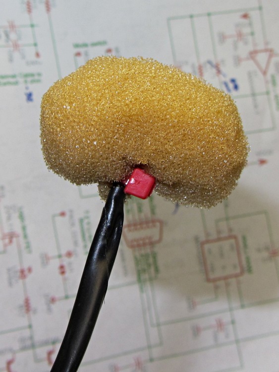
The foam comes from a sheet of Sonex acoustic foam baffle, snipped into a reasonable approximation of a ball, with a slit deep enough to surround the mic, and a cable tie holding it closed:
Foam mic ball on bike helmet boom
For what it’s worth, I’ve found that excessive wind noise correlates with too much mic gain. The mic rides about a finger’s width from the corner of my mouth, I talk at a normal volume, the amp supplies about 20 dB of gain, and we have no trouble with wind noise. The amp gain depends on the mic sensitivity, so your results will certainly differ; these mics came from the heap with no specs whatsoever.
I suppose wind noise also depends on the bike’s speed, but when I’m going that fast I don’t have enough brain or lungs left over to hold a conversation…
Our Toyota Sienna arrived with a blank cover plate where a fancier model would have a switch. It seemed a shame to let that space go to waste, so I popped the plate out, rummaged around in the heap, found a small circuit board with a blinky LED that just exactly fit the space available, and drilled a suitable hole:
Sienna anti-theft blinker – inside
When it’s installed in the van, it looks and acts just like the security system we don’t have. For all I know, that plate was for the security system control, so perhaps it’s an exact match!
Sienna anti-theft blinker – bezel
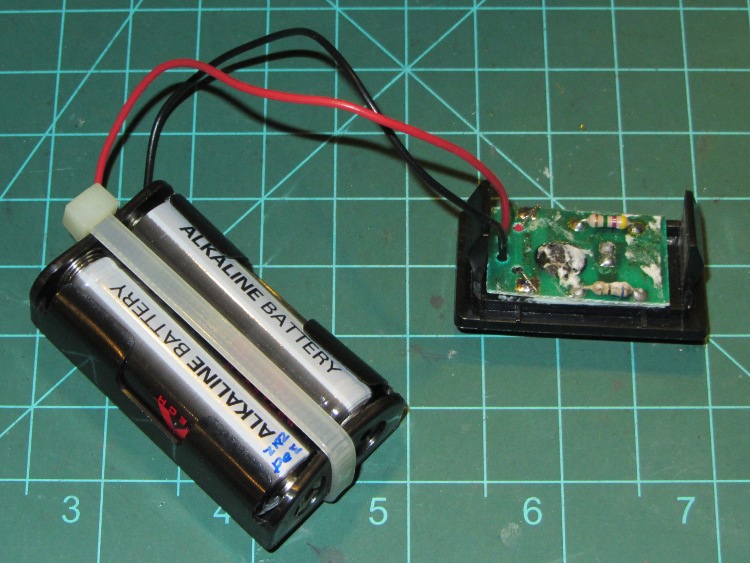
The batteries last about two years, a few months later I notice the lack of blinkiness (it’s hidden behind the steering wheel in my normal driving position), and eventually I replace the corroded batteries. This time, I had to replace the entire battery holder; things got pretty nasty in there.
As I recall, the PCB came from a fancy “greeting card” mailed to me by the Business Software Alliance, with the implied threat that if all my paperwork wasn’t up to par, my use of potentially unlicensed software would blow up in my face. That was back in the day when mailing something that pretended to be a bomb was considered a cute joke and when I actually ran more than one Windows PC.
It seems that Wouxun KG-UV3D HTs require nearly 0 V to activate the PTT input, which I discovered after the radio on Mary’s bike began acting intermittently. The TinyTrak3+ would transmit correctly, but the PTT button on the handlebar began to not work at all / work intermittently / work perfectly. The switch and cable were OK, pushing the button produced nearly 0 Ω at the 3.5 mm plug, the connections seemed solid, but the radio didn’t transmit reliably.
I finally got the thing to fail on the bench, which led to the discovery that:
Shorting the PTT input to the GPS+voice adapter PCB to ground didn’t make the radio transmit and
Data bursts from the TinyTrack3 worked perfectly
Gotcha!
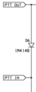
TT3 PTT In-Out
The TT3+ pulls its PTT OUT pin down from +5 V using a 2N2222A NPN transistor (off to the right in the schematic snippet), but, for reasons having to do with ESD, the input from the PTT switch on the handlebars goes through a 100 Ω series resistor, then passes to the TT3 board through PTT IN to D6 before joining the TT3 transistor collector. The low-active diode-ORed signal heads off through PTT OUT to a 10 Ω series resistor, thence to the KG-UV3D PTT input. D6 is an ordinary 1N4148, with the net result that the PTT input voltage at the radio dropped to 630 mV with the PTT button pressed.
Not finding anything else wrong, I replaced D6 with a BAT54 Schottky diode that pulled the PTT voltage down to 300 mV and the radio worked fine.
Of course, a BAT54 is a surface-mount diode, so I clipped off the unused no-connect lead (it’s the only way to be sure it doesn’t do anything) and tacked it down slaunchwise between the PCB thru-hole pads. If I had a BAT54C with common cathodes, I could replace both D5 and D6 in one shot, but D5 just pulls down a PIC input that has an ordinary logic-level threshold voltage.
I don’t know why the KG-UV3D PTT is so fussy, although it may really be a current-driven signal that requires more current than can flow through the 110 Ω + diode forward drop in series with the PTT button. Wouxun presents no specifications that I can find.
The identical circuitry on my bike works fine with the stock D6 diode and a presumably identical KG-UV3D. I should replace that diode before it gives me any trouble, but I’ll wait until I must take the box apart for some other reason.
One of the myriad cheap LED flashlights around the house & shop stopped working. This one consists of an aluminum shell with a pushbutton switch in the screw-on rear cap; somewhat to my surprise, the switch worked fine.
Poking around the PCB in the front revealed the problem: only friction held it in place against the springs contacting the three AA cell battery container. Pushing a bit harder shoved the lens and the LED / reflector / PCB assembly out:
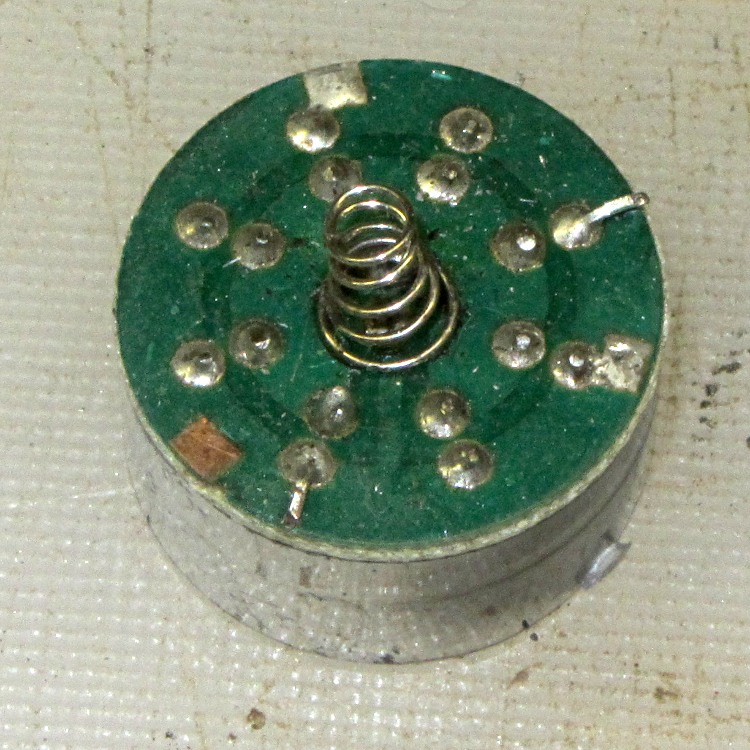
LED flashlight PCB
The spring in the middle contacts the positive battery terminal. Those three square pads pressing against a locating shoulder inside the shell, but two of the pads have a solder layer and one is bare. I don’t know if the long lead on the LED at about two o’clock is a deliberate attempt to form an additional contact.
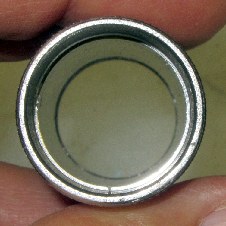
Peering inside the shell reveals three teeny nubs on the locating shoulder that could, presumably, dig into the solder pads:
LED flashlight – shell contact points
If you’re having trouble spotting them, so did I. Running a fingernail around the shoulder helps: one is at the bottom, another about 10 o’clock, and the third at about 1 o’clock. They’re not evenly spaced at 120° to match up with the pads.
With only friction holding the PCB in place, I understand why the flashlight didn’t work; given enough of an impact, the battery would push the PCB just far enough forward to make the connection at least intermittent.
I aligned the two solder-coated pads with two nubs, shoved everything together, pressed the lens firmly in place, and we’ll see how long that lasts…
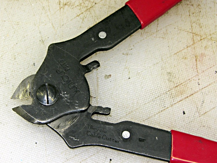
It should go without saying, but you do not cut music wire with diagonal cutters intended for electrical wire or the low-carbon steel shears built into wire strippers. I use a bicycle cable cutter that easily slices through the hard wire used in brake cables and their housing:
Every now and again I touch up the jaws with a diamond file to get rid of small dings; despite being hardened, those fine points seem particularly prone to burrs.
When you see an ordinary wire cutter with matching half-moons in each blade, you know what happened…