Ed Nisley's Blog: Shop notes, electronics, firmware, machinery, 3D printing, laser cuttery, and curiosities. Contents: 100% human thinking, 0% AI slop.
The tech reviewer for my Circuit Cellar columns on the MOSFET tester commented that the 32 kHz PWM frequency I used for the Peltier module temperature controller was much too high:
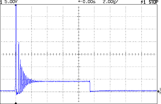
Peltier Noise – VDS – PWM Shutdown
He thought something around 1 Hz would be more appropriate.
Turns out we were both off by a bit. That reference suggests a PWM frequency in the 300-to-3000 Hz range. The lower limit avoids thermal cycling effects (the module’s thermal time constant is much slower) and, I presume, the higher limit avoids major losses from un-snubbed transients (they still occur, but with a very low duty cycle).
Peltier Turn-Off Transient
The Peltier PWM drive comes from PWM 10, which uses Timer 1. The VDS and ID setpoints come from PWM 11 and PWM 3, respectively, which use Timer 2. So I can just not tweak the Timer 1 PWM frequency, take the default 488 Hz, and it’s all good. That ever-popular post has the frequency-changing details.
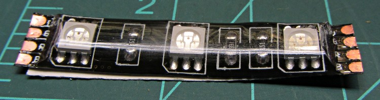
Another package from halfway around the planet brought 5 meters of waterproof RGB LED strip, which may be useful for projects like longboard lighting. Not having worked with a waterproof strip before, I snipped off a segment:
Waterproof RGB LED Strip – one segment
The waterproof coating seems to be a soft silicone or acrylic pour with roughly the consistency of Gummy Bear tummy, so cutting it off requires a delicate touch to avoid slicing the flex circuit board:
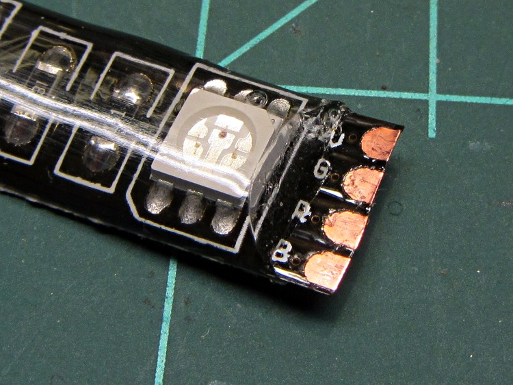
Waterproof RGB LED Strip – peeled top
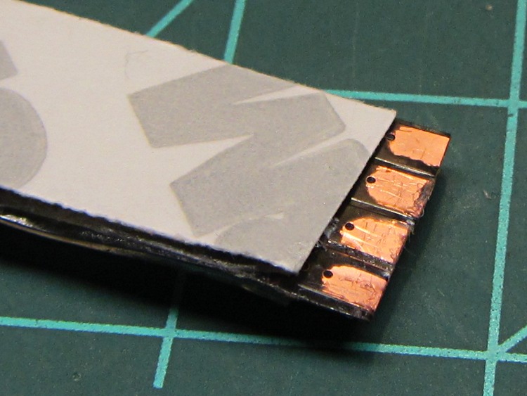
It doesn’t actually bond to the circuit board, though, and if you get a sharp blade underneath, can be peeled away. I suspect this means water will eventually make its way into the circuitry and you shouldn’t expect to submerge the strip in a fish tank. I scraped the contacts clean, which probably isn’t the right way to do it:
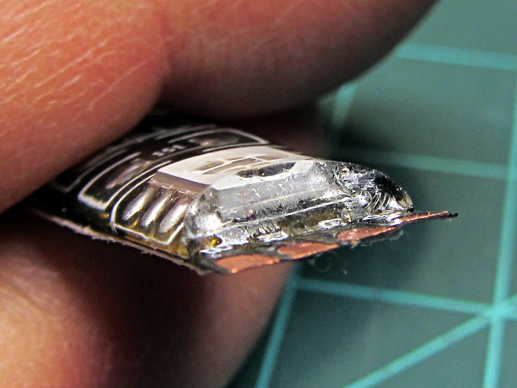
Waterproof RGB LED Strip – end view
The underside makes no pretension of being waterproof and you can peel / roll / rub the adhesive off the contacts:
Waterproof RGB LED Strip – peeled bottom
Does anyone else doubt the authenticity of that 3M logo? The production values look rather low, but maybe it’s just me.
The trouble with soldering contacts to the bottom is the ensuing lump that prevents good adhesive bonding. The trouble with soldering contacts on the top is the surgery required to remove the coating. You can get punch-through contacts with snake-bite fangs, but even the vendors admit to about a 20% failure rate, which implies it’s pretty much a crapshoot.
Two lots of linear Hall Effect sensors arrived from halfway around the planet, labeled AH49E and OH49E, and roughly corresponding to the original Honeywell SS49E. The Honeywell datasheet has a non-obvious pinout diagram (that one is better), so I poked one of them into a breadboard and tried it out.
Fortunately, I got it on the first try. Facing the tapered side, with the leads downward, pin 1 is on your left:
Power – typically +5 V
Ground
Output – 0 gauss = 2.5 V
The chip [may | may not], depending on which datasheet you use and which part you have, include an internal 65 μA load on the current source, so you [may not | may] need an external load resistor.
Without a load resistor, this one worked fine. Old-school ferrite and ceramic magnets push it about 1 V off-center, neodymium magnets saturate the output.
Corroded Grounding Strap – Walkway Over the Hudson
Spotted this through the railing on the north side of the Walkway Over the Hudson:
I’m not sure what it’s bonding to the bridge structure, but the corrosion where the braid touches the I-beam suggests an electrical potential drives the reaction. There’s stout bonding braid connecting all the railing sections together, but this braid wanders off below the decking and seems too casual / flimsy for lightning protection.
The rivets date back to the late 1800s. I suspect that bolt won’t last nearly as long…
Although the contacts passing power to the Wouxun HT worked well, they were obviously (in retrospect, as always) in the wrong place. Recently I rode the bike over a major bump and heard the radio reboot (it gives off two low-speed Morse “M” characters), which suggests at least one of the screw heads just barely touches the radio’s spring contacts.
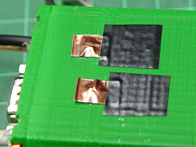
Two folded-under strips of copper tape may work around that problem until I build a whole ‘nother interface:
Copper foil on power contacts
The black tape adds emphasis to the lightly sticky end of the copper tape. The folded-under ends lie to the left in the picture, so there’s a continuous copper sheet connecting the radio battery contacts to the screw heads on the green case. It’s not a huge cross-sectional area, but … it’s better than no area at all.
The last time I tried this fix, I used woven copper mesh tape. This time, the solid copper tape was on top of the TLB (Tape Lookaside Buffer) holding the specialty tapes. Either should work fine.
So the outdoor thermometer hanging over my desk became very, very faint, which suggested it was time for a new alkaline cell. The last time that happened, the insides were pretty bad, so I expected the worst, but, surprisingly, neither the cell nor the negative contact spring were corroded. So I popped in a new cell, buttoned it up, and … it didn’t work. At all. As in: blank display.
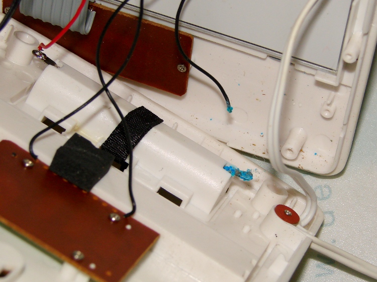
Taking the back off revealed the simple cause:
Outdoor thermometer – corroded battery lead
Evidently, the negative terminal wire had corroded completely through and popped off when I replaced the cell. There’s plenty of green-blue corrosion on the terminal inside the case, where it can’t be seen from outside; three years ago I cleaned up both the outside and inside, so this is new news.
The negative wire was discolored all the way from end to end and couldn’t be soldered. I think the corrosion products are just slightly hygroscopic and wick their way along the copper strands inside the insulation: the solder pad on the circuit board was also discolored.
I removed the terminal, neutralized the alkaline corrosion, ran it through an Evapo-Rust bath, scrubbed it clean, installed it, replaced both the positive and negative wires, resoldered everything, and it works perfectly again.
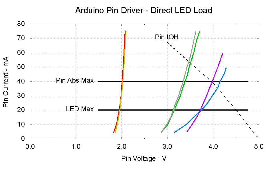
The dotted curve comes from Figure 29-22 of the ATmega168 datatsheet and shows the typical source current vs. voltage for a digital output pin on your favorite Arduino.
The cheerful colored curves show the current vs. voltage characteristics of some random LEDs, with data from the same curve tracer setup as those.
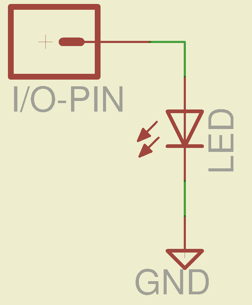
Given a particular LED directly connected between an Arduino output pin and circuit common (without the formality of a current-limiting ballast resistor), the intersection of the dotted output pin curve with the colored LED curve gives you the current & voltage at the pin. For example, the violet LED would operate at 4 V and 40 mA.
Some gotchas:
Typical 5 mm LEDs, of the sort one might use for this experiment, have a maximum DC current limit of 20 mA
Arduino output pins have an absolute maximum current limit of 40 mA
So all of the direct solutions drive too much current through the LED. Although the blue and violet LEDs don’t quite exceed the output pin limit, the others certainly do. Those old standby red & amber LEDs would have absurdly high intercepts, well beyond the limit of sanity, in the region where the data you see here breaks down, where the pin driver gives up and goes poof, not that that ever stopped anybody from trying.
You’ve probably seen somebody do it. Next time, aim ’em here in a non-confrontational manner… [grin]
My Arduino Survival Guide presentation has other info that may help that poor sweating Arduino survive. You don’t get my performance-art patter, but the pictures and captions should carry the tale…
As part of conjuring up this plot, I discovered that, for whatever reason, Gnuplot’s TrueType font rendering (via gdlib) no longer works in Xubuntu 12.04: the font name has no effect whatsoever, but the point size does.
The Gnuplot source code:
#!/bin/sh
#-- overhead
export GDFONTPATH="/usr/share/fonts/truetype/msttcorefonts"
Pinfile="ATmega Pin Driver Data - Source.csv"
LEDfile="LED Data.csv"
base="Arduino Pin Driver - Direct LED Load"
Outfile="${base}.png"
echo Output file: ${Outfile}
fontname="Arial"
echo Font: ${fontname}
#-- do it
gnuplot << EOF
#set term x11
set term png font "${fontname},18" size 950,600
set output "${Outfile}"
set title "${base}" font "${fontname},22"
set key noautotitles
unset mouse
set bmargin 4
set grid xtics ytics
set xlabel "Pin Voltage - V"
set format x "%4.1f"
set xrange [0:${vds_max}]
#set xtics 0,5
set mxtics 2
#set ytics nomirror autofreq
set ylabel "Pin Current - mA"
#set format y "%4.1f"
set yrange [0:80]
#set mytics 2
#set y2label "Drain Resistance - RDS - mohm"
#set y2tics nomirror autofreq ${rds_tics}
#set format y2 "%3.0f"
#set y2range [0:${rds_max}]
#set y2tics 32
#set rmargin 9
set datafile separator "\t"
set label "Pin IOH" at 3.0,70 center font "${fontname},18"
set label "Pin Abs Max" at 1.4,40 right font "${fontname},18"
set arrow from 1.5,40 to 4.75,40 lw 4 nohead
set label "LED Max" at 1.4,20 right font "${fontname},18"
set arrow from 1.5,20 to 4.75,20 lw 4 nohead
plot \
"${Pinfile}" using 1:3 with lines lt 0 lw 3 lc -1 ,\
"${LEDfile}" using (\$5/1000):((\$1>0)?\$2/1000:NaN) index 0:0 with lines lw 3 lc 1 ,\
"${LEDfile}" using (\$5/1000):((\$1>0)?\$2/1000:NaN) index 1:1 with lines lw 3 lc 2 ,\
"${LEDfile}" using (\$5/1000):((\$1>0)?\$2/1000:NaN) index 2:2 with lines lw 3 lc 0 ,\
"${LEDfile}" using (\$5/1000):((\$1>0)?\$2/1000:NaN) index 3:3 with lines lw 3 lc 4 ,\
"${LEDfile}" using (\$5/1000):((\$1>0)?\$2/1000:NaN) index 4:4 with lines lw 3 lc 3 ,\
"${LEDfile}" using (\$5/1000):((\$1>0)?\$2/1000:NaN) index 5:5 with lines lw 3 lc 7
EOF
A few early risers got to see a completely broken listing, with all the quotes and brackets and suchlike reduced to the usual HTML escaped gibberish…