Ed Nisley's Blog: Shop notes, electronics, firmware, machinery, 3D printing, laser cuttery, and curiosities. Contents: 100% human thinking, 0% AI slop.
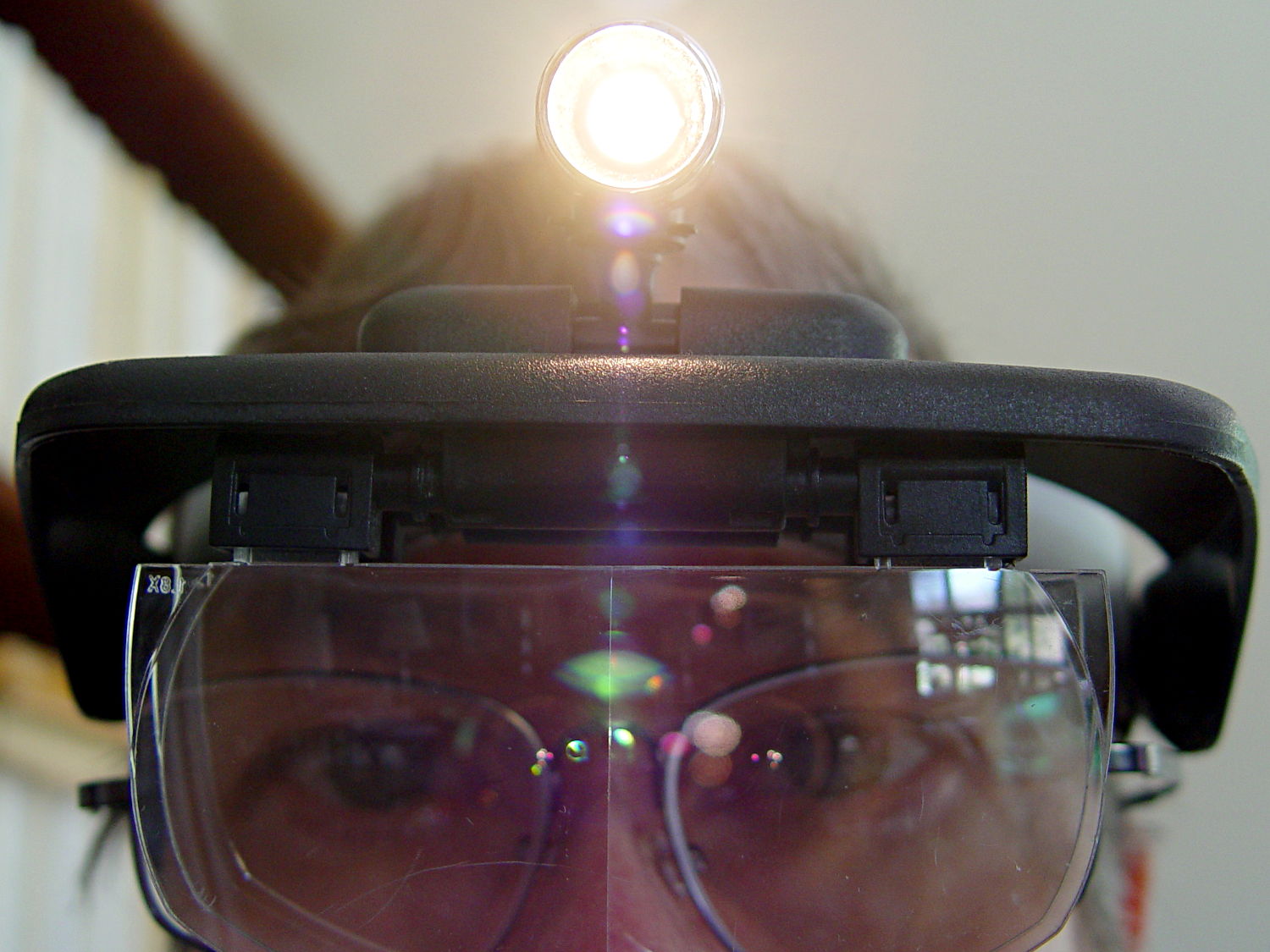
One of my headband magnifiers has a headlight above the brim, an incandescent flashlight bulb powered by a pair of AAA alkaline cells, that hasn’t worked well since the day I bought it. This being a time of finishing small projects, I finally tore it apart and discovered that the cells and contacts were in fine shape (!), the bulb (remember bulbs?) worked, the wiring was OK, but the switch was bad.
Magnifying headband – lamp switch
The switch body seems to be firmly anchored in place, so I pried that red base plate off in situ, un-bent the silver-plated (!) spring-contact-actuator, and reassembled it in reverse order. No pictures, as it took less time to do than to tell, but it now works perfectly… most likely, for the first time ever.
Stop squirming! This can be much more painful…
Magnifying headband – in action
I’m mildly tempted to hotwire the guts of a white LED flashlight into the thing, but that would require either another AA cell or a booster circuit and I’m not ready for that just yet.
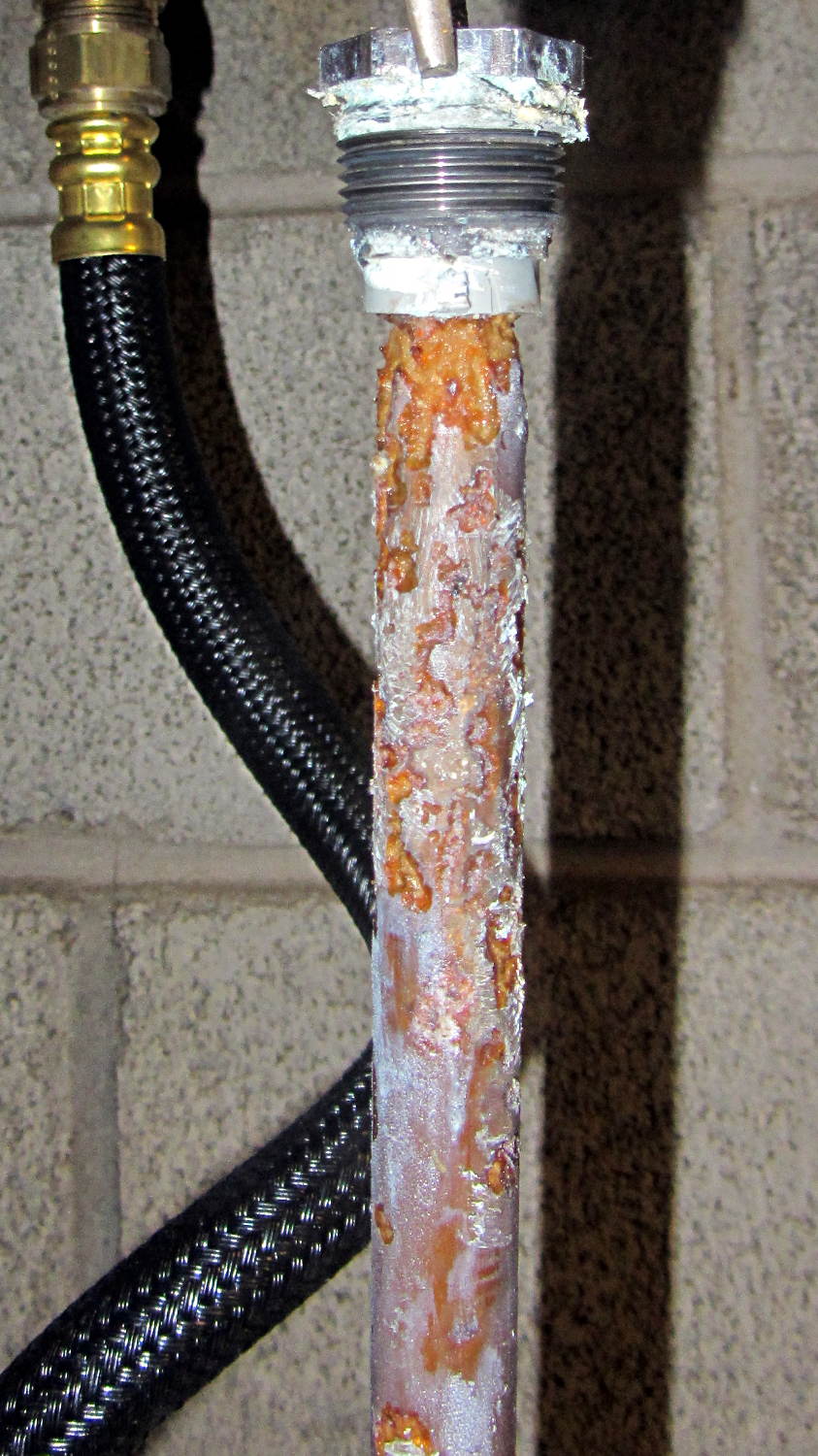
The Whirlpool water heater anode rod is corroding nicely:
Whirlpool anode rod – 2014-04
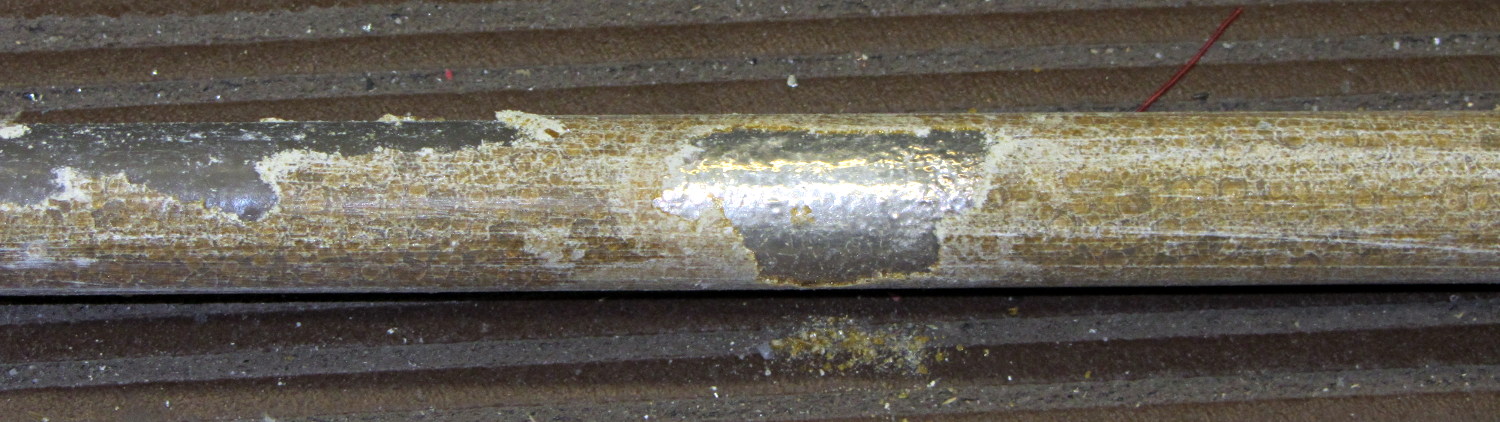
The new GE water heater anode rod seems to be passivating:
GE anode rod – coated – 2014-04
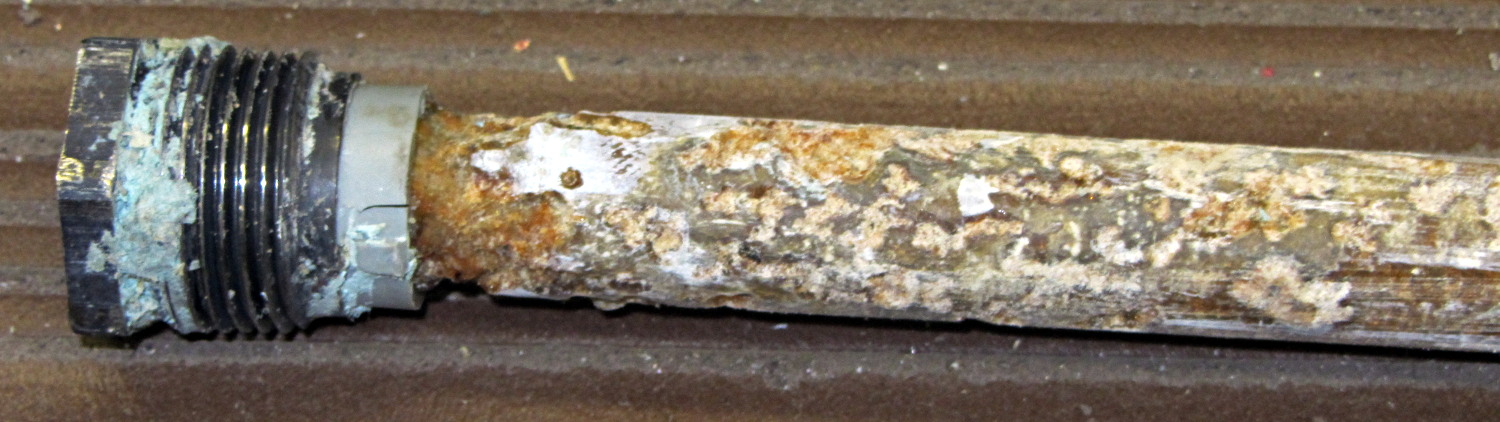
There’s some corrosion up near the bolt head, so it’s not entirely asleep:
GE anode rod – bolt – 2014-04
I hammered the coating off the rod, scuffed the shiny parts with coarse sandpaper, wiped off the dust, and stuck it back in its socket. We’ll see what it looks like next year.
Both tanks flushed nicely without too much sediment.
Two 40 W incandescent bulbs in the front bathroom burned out within a few days of each other. Being that type of guy, I know that I installed this bulb nine years ago:
Bulb base – install date
The date is easier to read with the bulb in hand: 13 Feb 05. The (5 yrs) indicates the previous bulb in that socket lasted five years.
The other bulb date went in during March 09, so it survived only five years; the previous bulb lasted 6 years.
Even though 40 W incandescent bulbs are history, maybe I have enough spares on the shelf that the next owner can replace ’em with cheap LEDs.
This may not be science, but it does have numbers…
The knockoff Arduino Pro Mini I used for the strobe photography controller ran the default Blink sketch perfectly, but didn’t respond to its own Reset pushbutton. Probing the Reset line at pin 29 on the microcontroller showed that the pushbutton didn’t pull the +5 V line to ground, so the switch was broken, a trace was broken, or …
Touching the soldering iron to a switch pin caused the whole thing to pop loose. One glance at the pads tells you something’s badly wrong:
Arduino Pro Mini Knockoff – cold solder joints
A closeup, rotated a quarter-turn clockwise:
Arduino Pro Mini Knockoff – cold solder joint – detail
That’s the nicest picture of cold solder joints you’ve seen in a while, isn’t it?
Resoldering the switch solved the problem and, while the iron was hot, I touched all the microcontroller pins, too, just in case…
Natural PLA provides a nice, crystalline appearance:
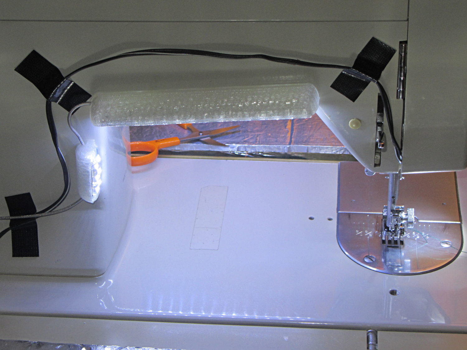
Kenmore 158 Sewing Machine – Cool white LEDs – rear no flash
Cool white LEDs have somewhat higher lumen/watt efficiency, but the real gain came from doubling the number of LEDs:
Kenmore 158 Sewing Machine – Cool white LEDs – front flash
I overvolted the warm white LEDs to 14 V to get closer to 20 mA/segment, but the cool white ones run pretty close to 20 mA at 12 V, so I didn’t bother.
Commercial versions of this hack secure the wiring with little white clips and foam tape, so I should conjure up something like that. Mary specifically did not want the lights affixed under the arm, though, so those things weren’t even in the running.
The OpenSCAD source code widens the mount and moves the wiring conduit a little bit, to simplify the connections to both strips, but is otherwise identical to the earlier version:
// LED Strip Lighting Brackets for Kenmore Model 158 Sewing Machine
// Ed Nisley - KE4ZNU - March 2014

Layout = "Build";			// Build Show Channels Strip

//- Extrusion parameters must match reality!
//  Print with 2 shells and 3 solid layers

ThreadThick = 0.20;
ThreadWidth = 0.40;

HoleWindage = 0.2;			// extra clearance

Protrusion = 0.1;			// make holes end cleanly

AlignPinOD = 1.70;			// assembly alignment pins: filament dia

inch = 25.4;

function IntegerMultiple(Size,Unit) = Unit * ceil(Size / Unit);

//----------------------
// Dimensions

Segment = [25.0,10.0,3.0];		//  size of each LED segment
SEGLENGTH = 0;
SEGWIDTH = 1;
SEGHEIGHT = 2;

WireChannel = 3.0;				// wire routing channel

StripHeight = 12.0;				// sticky tape width
StripSides = 8*4;

DefaultLayout = [1,2,"Wire","NoWire"];
NUMSEGS = 0;
NUMSTRIPS = 1;
WIRELEFT = 2;
WIRERIGHT = 3;

EndCapSides = StripSides;

CapSpace = 2.0;						// build spacing for endcaps
BuildSpace = 3.0;					// spacing between objects on platform

//----------------------
// Useful routines

module PolyCyl(Dia,Height,ForceSides=0) {			// based on nophead's polyholes

  Sides = (ForceSides != 0) ? ForceSides : (ceil(Dia) + 2);

  FixDia = Dia / cos(180/Sides);

  cylinder(r=(FixDia + HoleWindage)/2,
           h=Height,
           $fn=Sides);
}

module ShowPegGrid(Space = 10.0,Size = 1.0) {

  RangeX = floor(100 / Space);
  RangeY = floor(125 / Space);

	for (x=[-RangeX:RangeX])
	  for (y=[-RangeY:RangeY])
		translate([x*Space,y*Space,Size/2])
		  %cube(Size,center=true);

}

//-- The negative space used to thread wires into the endcap

module MakeWireChannel(Layout = DefaultLayout,Which = "Left") {

	EndCap = [(2*WireChannel + 1.0),Layout[NUMSTRIPS]*Segment[SEGWIDTH],StripHeight];	// radii of end cap spheroid

	HalfSpace = EndCap[0] * ((Which == "Left") ? 1 : -1);

	render(convexity=2)
	translate([0,Segment[SEGWIDTH]/2,0])
		intersection() {
			union() {
				cube([2*WireChannel,WireChannel,EndCap[2]],center=true);
				translate([-2*EndCap[0],0,EndCap[2]/2])
					rotate([0,90,0]) rotate(180/6)
						PolyCyl(WireChannel,4*EndCap[0],6);
			}
			translate([HalfSpace,0,(EndCap[2] - Protrusion)]) {
				cube(2*EndCap,center=true);
			}
		}
}

//-- The whole strip, minus wiring channels

module MakeStrip(Layout = DefaultLayout) {

	EndCap = [(2*WireChannel + 1.0),Layout[NUMSTRIPS]*Segment[SEGWIDTH],StripHeight];	// radii of end cap spheroid

	BarLength = Layout[NUMSEGS] * Segment[SEGLENGTH];				// central bar length

	hull()
		difference() {
			for (x = [-1,1])						// endcaps as spheroids
				translate([x*BarLength/2,0,0])
					resize(2*EndCap) rotate([0,90,0]) sphere(1.0,$fn=EndCapSides);
			translate([0,0,-EndCap[2]])
				cube([2*BarLength,3*EndCap[1],2*EndCap[2]],center=true);
			translate([0,-EndCap[1],0])
				cube([2*BarLength,2*EndCap[1],3*EndCap[2]],center=true);
		}

}

//-- Cut wiring channels out of strip

module MakeMount(Layout = DefaultLayout) {

	BarLength = Layout[NUMSEGS] * Segment[SEGLENGTH];

	difference() {
		MakeStrip(Layout);
		if (Layout[WIRELEFT] == "Wire")
			translate([BarLength/2,0,0])
				MakeWireChannel(Layout,"Left");
		if (Layout[WIRERIGHT] == "Wire")
			translate([-BarLength/2,0,0])
				MakeWireChannel(Layout,"Right");
	}
}

//- Build it

ShowPegGrid();

if (Layout == "Channels") {
	translate([ (2*WireChannel + 1.0),0,0]) MakeWireChannel(DefaultLayout,"Left");
	translate([-(2*WireChannel + 1.0),0,0]) MakeWireChannel(DefaultLayout,"Right");
}

if (Layout == "Strip") {
	MakeStrip(DefaultLayout);
}

if (Layout == "Show") {
	MakeMount(DefaultLayout);
}

if (Layout == "Build") {

	translate([0,(3*Segment[SEGWIDTH]),0]) MakeMount([1,2,"Wire","Wire"]);		// rear left side, vertical
	translate([0,0,0]) MakeMount([5,2,"Wire","NoWire"]);				// rear top, across arm
	translate([0,-(3*Segment[SEGWIDTH]),0]) MakeMount([6,2,"NoWire","Wire"]);	// front top, across arm
}
During my monthly data logging, I replace any weak CR2032 cells in the Hobo data loggers and, being that type of guy, I write the current date and the elapsed time since the last replacement on the top of the cells. This month I had to replace two cells:
Energizer CR2023 – early failures
Huh.
It seems the previous Energizer CR2023 cells in those loggers lasted for more than the usual year, but these cells from the same lot with the same date code failed in two weeks (my last monthly science was unusually late, because distraction). The YA date code (printed on the other side of the cell) isn’t helpful (that Q&A list shows the problem), but they’re supposed to have an eight year shelf life. As nearly as I can tell, these are getting on toward five years on my shelf, so maybe they spent a bit more time on somebody else’s shelf than the seller claimed.
A solderless breadboard sufficed for the simple circuitry behind the strobe controller:
Strobe Photography – control breadboard
I used a separate 7.5 V supply for the Arduino Pro Mini to keep the relay noise out of the VCC circuit, but that’s probably not really necessary; you could back-drive the Pro Mini’s regulator with +5 V and it’d be perfectly happy. There’s a +5 V wall wart for the relay, LEDs, and so forth.
Protip: you do not want to drive all the other circuitry through the Pro Mini’s tiny little regulator. Work out the power dissipation in the regulator caused by a 130 Ω relay, about 10 mA for the laser, 100 mA for the white LED, and whatever the Pro Mini draws. Yeah, some of those are intermittent loads, but work it out anyway.
A 1.5 V bench supply powers the Xenon strobe in place of the AA alkaline cell I used at first. The boost circuit pins the supply at 3 A for a few seconds, then settles at about 350 mA (!) while idling; no wonder the poor little AA cells don’t last very long!
The control program is also dead simple; it’s mostly a state machine that notices when the photocurrent drops to zero, then steps through a series of fixed delays while turning the laser, LED, and strobe outputs on and off.
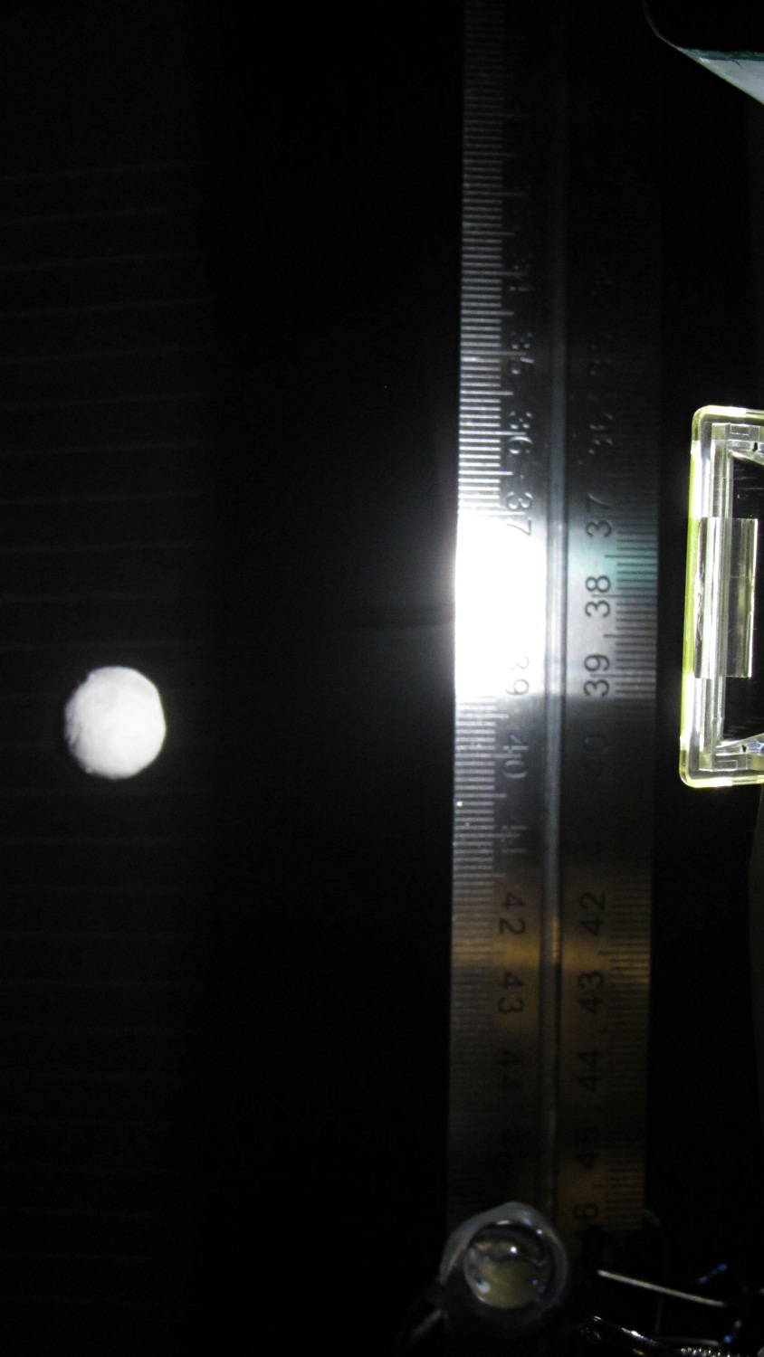
The default values highlight a falling object about 200 mm below the laser beam-break sensor, assuming you release the object just above the beam:
Ball at 200 mm – detail
The laser beam is at the 200 mm mark, so that ball passing 400 mm has dropped 200 mm.
The quadrature encoder knob recycles the same interrupt handler I used earlier, with the shaft button selecting either the LED delay (pushed) or the Xenon strobe delay (released). There’s precious little error checking, as befits a quick hack job, so use at your own risk…
The Arduino source code:
// Optical flash triggering
// Ed Nisley - KE4ANU - March 2014

//----------
// Pin assignments

const byte PIN_KNOB_A = 2;			// knob A switch - must be on ext interrupt 2
const byte PIN_KNOB_B = 4;			//  .. B switch
const byte PIN_KNOB_SWITCH = A3;	//  .. shaft push switch

const byte PIN_PHOTOCURRENT = A0;	// photodiode current input

const byte PIN_LASER = 8;   		// laser drive -active
const byte PIN_LED = 7;		   		// LED drive -active
const byte PIN_FLASH = 12;			// Xenon flash relay -active

const byte PIN_SYNC = 13;			// scope sync - and Arduino LED

//----------
// Constants

enum FALLING_STATES {F_IDLE,F_WAIT,F_DETECT,F_PREFALL,F_LED,F_MD,F_FLASH,F_CLEAR};

enum KNOB_STATES {KNOB_CLICK_0,KNOB_CLICK_1};

//----------
// Globals

const unsigned long UPDATEMS = 250;	// update displays only this many ms apart

volatile char KnobCounter = 0;
volatile byte KnobState;

byte Button, PrevButton;

byte Falling = F_IDLE;				// cold start the detection state machine

unsigned long FallStart;			// when we we detected the falling object

unsigned int DetectLevel = 200;		// ADC reading for object detection

unsigned int DelayLED = 1;			// ms from trigger detect to LED preflash

unsigned int DelayFlash = 180;		//  ... to Xenon flash

unsigned int DelayClear = 6000;		//  ... after impact to allow camera restart

const byte PulseLED = 50;			// ms LED on to pass motion detection threshold
const byte PulseFlash = 20;			// ms Xenon flash relay on

const unsigned int RelayAdvance = 3;	// ms relay activation to Xenon flash

unsigned long MillisNow;
unsigned long MillisThen;

//-- Helper routine for printf()

int s_putc(char c, FILE *t) {
  Serial.write(c);
}

//-- Knob interrupt handler

void KnobHandler(void)
{
	byte Inputs;
	Inputs = digitalRead(PIN_KNOB_B) << 1 | digitalRead(PIN_KNOB_A);  // align raw inputs
//	Inputs ^= 0x02;                             // fix direction

	switch (KnobState << 2 | Inputs) {
	case 0x00 : 				// 0 00 - glitch
        break;
	case 0x01 : 				 // 0 01 - UP to 1
        KnobCounter++;
		KnobState = KNOB_CLICK_1;
		break;
	case 0x03 : 				 // 0 11 - DOWN to 1
        KnobCounter--;
		KnobState = KNOB_CLICK_1;
		break;
	case 0x02 : 				 // 0 10 - glitch
        break;
	case 0x04 : 				 // 1 00 - DOWN to 0
        KnobCounter--;
		KnobState = KNOB_CLICK_0;
		break;
	case 0x05 : 				 // 1 01 - glitch
        break;
	case 0x07 : 				 // 1 11 - glitch
        break;
	case 0x06 : 				 // 1 10 - UP to 0
        KnobCounter++;
		KnobState = KNOB_CLICK_0;
		break;
	default :  					// something is broken!
        KnobCounter = 0;
		KnobState = KNOB_CLICK_0;
	}
}

//------------------
// Set things up

void setup() {

	pinMode(PIN_SYNC,OUTPUT);
	digitalWrite(PIN_SYNC,LOW);			// show we arrived

	pinMode(PIN_KNOB_B,INPUT_PULLUP);
	pinMode(PIN_KNOB_A,INPUT_PULLUP);
	pinMode(PIN_KNOB_SWITCH,INPUT_PULLUP);

    pinMode(PIN_LASER,OUTPUT);
    digitalWrite(PIN_LASER,HIGH);

    pinMode(PIN_LED,OUTPUT);
    digitalWrite(PIN_LED,HIGH);

    pinMode(PIN_FLASH,OUTPUT);
    digitalWrite(PIN_FLASH,HIGH);

	KnobState = digitalRead(PIN_KNOB_A);
	Button = PrevButton = !digitalRead(PIN_KNOB_SWITCH);

	attachInterrupt((PIN_KNOB_A - 2),KnobHandler,CHANGE);

	Falling = F_IDLE;

	Serial.begin(9600);
	fdevopen(&s_putc,0);				// set up serial output for printf()

	printf("Xenon Flash Trigger\r\nEd Nisley - KE4ZNU - March 2014\r\n");

	MillisThen = millis();

}

//------------------
// Go flash!

void loop() {

	MillisNow = millis();

	if (KnobCounter) {
		Button = !digitalRead(PIN_KNOB_SWITCH);
		if (Button)
			DelayLED += KnobCounter;
		else
			DelayFlash += KnobCounter;

		DelayLED = min(DelayLED,DelayFlash - PulseLED);
		printf("Knob: %d, LED: %d, Flash: %d\n",KnobCounter,DelayLED,DelayFlash);
		KnobCounter = 0;
	}

	digitalWrite(PIN_SYNC,HIGH);

	switch (Falling) {
	case F_IDLE :								// turn on laser for object detection
		digitalWrite(PIN_LASER,LOW);
		printf("Laser on, stabilizing... ");
		while (analogRead(PIN_PHOTOCURRENT) <= DetectLevel) {
			printf("*");
		}
		printf("\nReady!\n");
		Falling = F_WAIT;
		break;
	case F_WAIT :								// record starting time of beam break
		if (analogRead(PIN_PHOTOCURRENT) < DetectLevel) {
			FallStart = millis();
			Falling = F_DETECT;
		}
		break;
	case F_DETECT :								// turn off laser to signal detection
		digitalWrite(PIN_LASER,HIGH);
		Falling = F_PREFALL;
		break;
	case F_PREFALL :							// turn on LED to trigger camera motion detection
		if ((millis() - FallStart) >= DelayLED) {
			digitalWrite(PIN_LED,LOW);
			Falling = F_LED;
		}
		break;
	case F_LED : 								// turn off LED
		if ((millis() - FallStart) >= (DelayLED + PulseLED)) {
			digitalWrite(PIN_LED,HIGH);
			Falling = F_MD;
		}
		break;
	case F_MD :									// fire the strobe to take picture
		if ((millis() - FallStart) >= (DelayFlash - RelayAdvance)) {
			digitalWrite(PIN_FLASH,LOW);
			Falling = F_FLASH;
		}
		break;
	case F_FLASH :								// turn off strobe relay
		if ((millis() - FallStart) >= (DelayFlash - RelayAdvance + PulseFlash)) {
			digitalWrite(PIN_FLASH,HIGH);
    		printf("Flash with LED delay: %d, Xenon delay: %d ...",DelayLED,DelayFlash);
			Falling = F_CLEAR;
		}
		break;
	case F_CLEAR :								// wait for camera to recycle
		if ((millis() - FallStart) >= DelayClear) {
			printf("done\n");
			Falling = F_IDLE;
		}
		break;
	default :
		printf("** Bad Falling state: %02X",Falling);
		Falling = F_IDLE;
	}

	digitalWrite(PIN_SYNC,LOW);

	if ((MillisNow - MillisThen) > UPDATEMS) {
//		printf("State: %02X\n",Falling);
		MillisThen = MillisNow;
	}

}