Ed Nisley's Blog: Shop notes, electronics, firmware, machinery, 3D printing, laser cuttery, and curiosities. Contents: 100% human thinking, 0% AI slop.
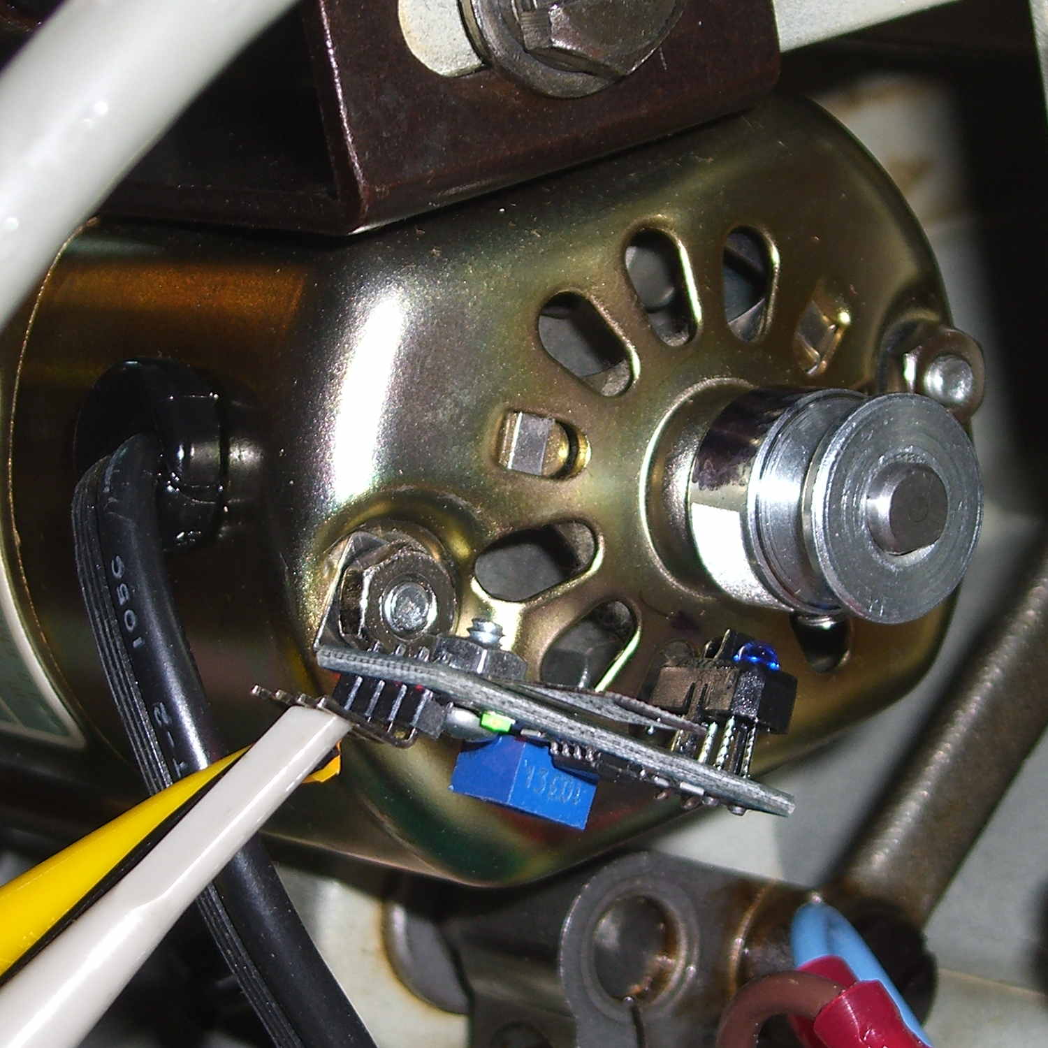
The first sensor bracket came from the scrap pile, but showed that it would produce 1/rev pulses from the motor shaft pulley. The positioning wasn’t quite right, so I made another bracket that put the TCRT5000 sensor at right angles to the pulley:
TCTR5000 Motor RPM Sensor – end view
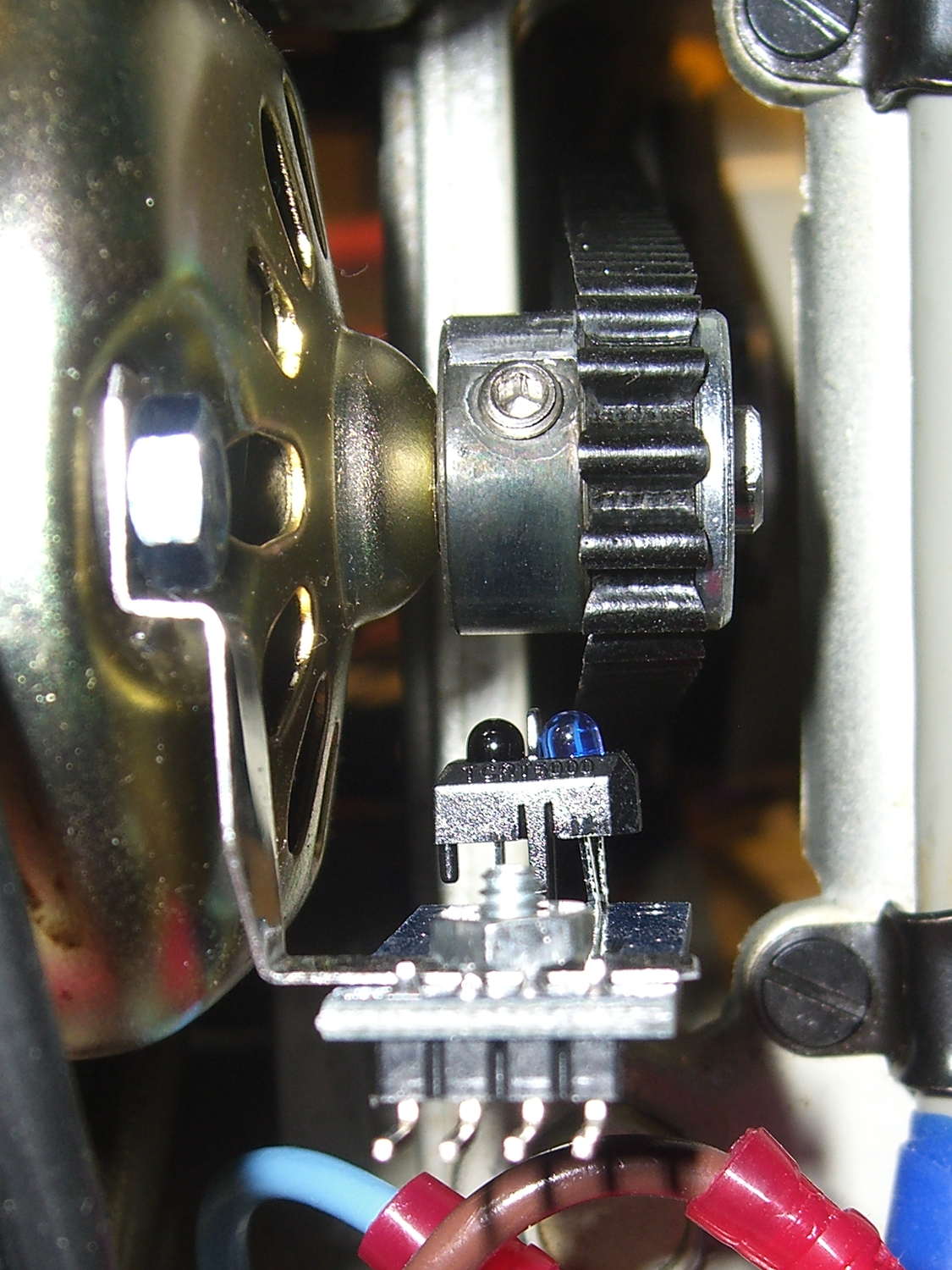
All of the sensors have a rakish tilt over their PCB, so at some point I must resolder them:
TCTR5000 Motor RPM Sensor – side view
It might not matter, as the phototransistor on the left peers directly at the pulley, with the LED on the right acting as a floodlight.
“Made another bracket” sounds like the metal sprang fully formed from the concept. Herewith, the early contestants atop a sketch and the flat layout for The Ultimate Bracket:
Motor RPM Sensor Brackets
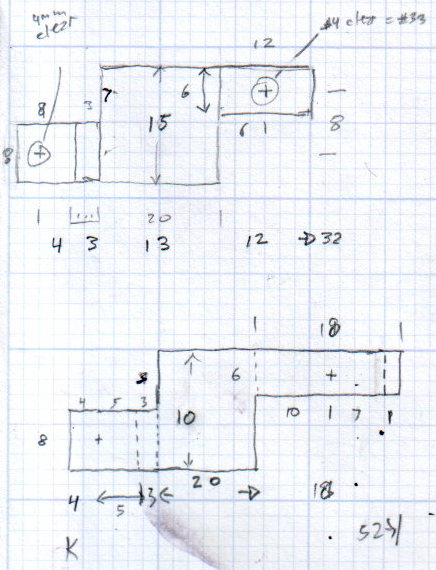
A closer look at that final dimension sketch, because I’ll need it again:
RPM Bracket Dimensions
The vertical size of the center section (12 mm) sets the perpendicular distance of the sensor from the shaft. The horizontal size (14 mm) controls the pulley-to-sensor spacing.
The horizontal distance from the center section to the hole on the right (10 mm) adjusts the sensor spacing parallel to the shaft.
I cut the overall rectangle with tin snips, drilled & cleaned the holes, applied a nibbling tool to the details, trimmed the corners, filed off sharp edges & spines, and it was all good.
The doodles for the first few attempts, as I don’t want to repeat those mistakes:
Bracket Doodles
All in all, a few more hours of Quality Shop Time than I expected…
Well, that’s not what I expected: the “new” Wasabi batteries perform worse than the three year old Canon OEM battery and no better than the crap batteries from eBay.
Just to be sure, I ran two tests on each of the three new batteries. Unlike the NP-BX1 batteries, these deliver a lower voltage than the Canon OEM battery and have a much lower capacity. The camera cuts off at 3.5 V, so the new batteries deliver 2/3 the run time of the old OEM battery
Sheesh…
Tech support at Blue Nook (I am not making that up) says they’ll send me a couple of batteries from their next shipment to see if something’s wrong with this batch; all the batteries have date code BNF27.
The Sony HDR-AS30V helmet camera can record about 5.5 h of 1920×1080 60 fps video on a 64 GB Micro-SD card, but a single NP-BX1 battery provides a 1.5 h run time, tops. Having had a good experience with the previous Wasabi batteries, I picked up three more and ran all six through the battery tester:
Sony NP-BX1 – OEM Wasabi – 2014-10-03
The red curve is the Sony OEM battery, the two lower curves are the Wasabi batteries from January, and the upper three come from the new Wasabi batteries. All in all, they look good to me.
These curves aren’t directly comparable to the older ones, as I’ve bumped the discharge to 500 mA to better match the actual camera load. These worked out to about two hours apiece, so the camera must draw around 600 or 700 mA.
The Wasabi batteries deliver a higher voltage than the Sony OEM battery over nearly all of the discharge curve. The older ones delivered almost exactly the same run time, which leads me to believe the camera cuts off at 2.8 V, too, with a boost power supply extracting all the energy under the curve.
I suppose a 1.5 h run time makes sense for downhill skiiing, but it’s painfully short for bike trips.
A quick-and-dirty bracket (made from a leftover strip in the pile of chassis clips) affixed an IR reflective sensor (based on the ubiquitous TCRT5000 module) to the sewing machine motor:
TCRT5000 sensor on motor
That’s scribbling black Sharpie around the retroreflective tape for the laser tachometer, which worked just about as poorly as you’d expect. Retroreflective tape, by definition, reflects the light directly back at the LED, but in this case you want it bounced to the photosensor.
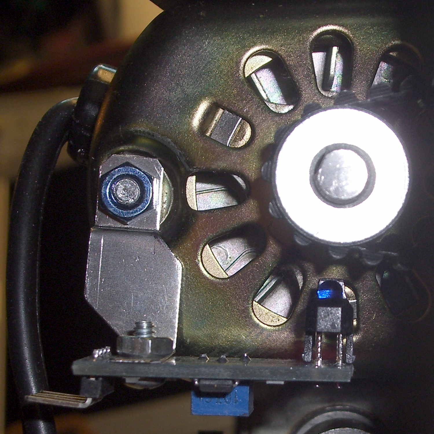
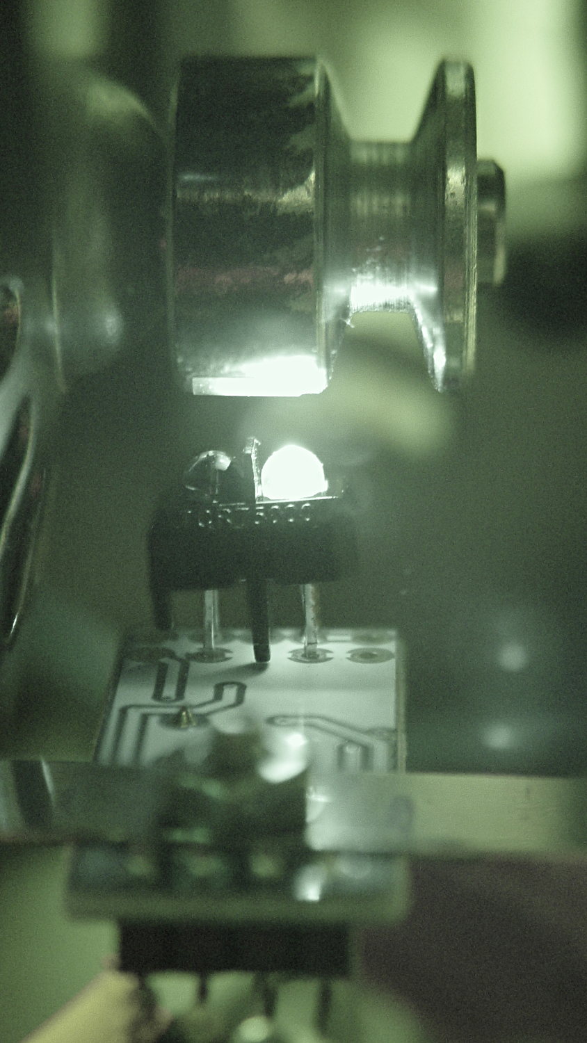
An IR view shows the geometry and highlights the LED:
TCRT5000 sensor – IR view
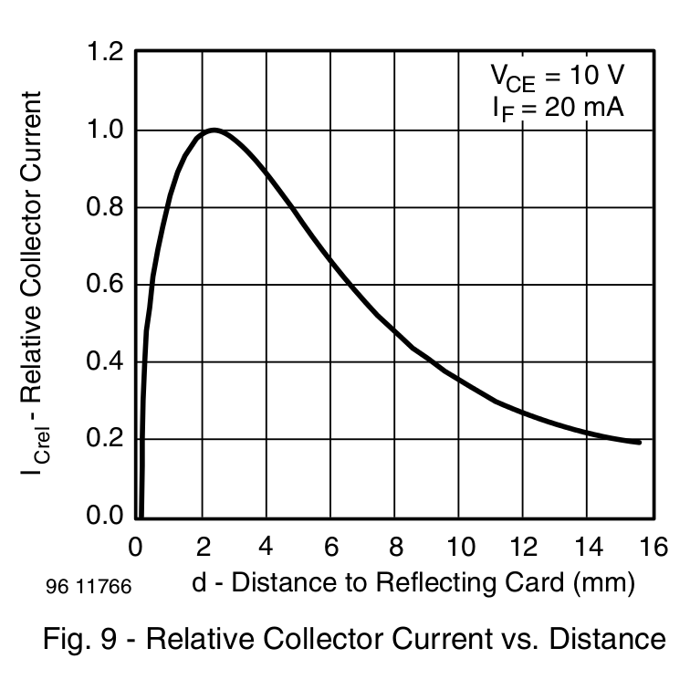
The TCRT5000 datasheet suggests that the peak operating distance is 2.5 mm, roughly attained by tinkering with the bracket. The datasheet graph shows that anything between 1 and 5 mm should be just fine:
IR Reflective Sensor module – TCRT5000 – response vs distance
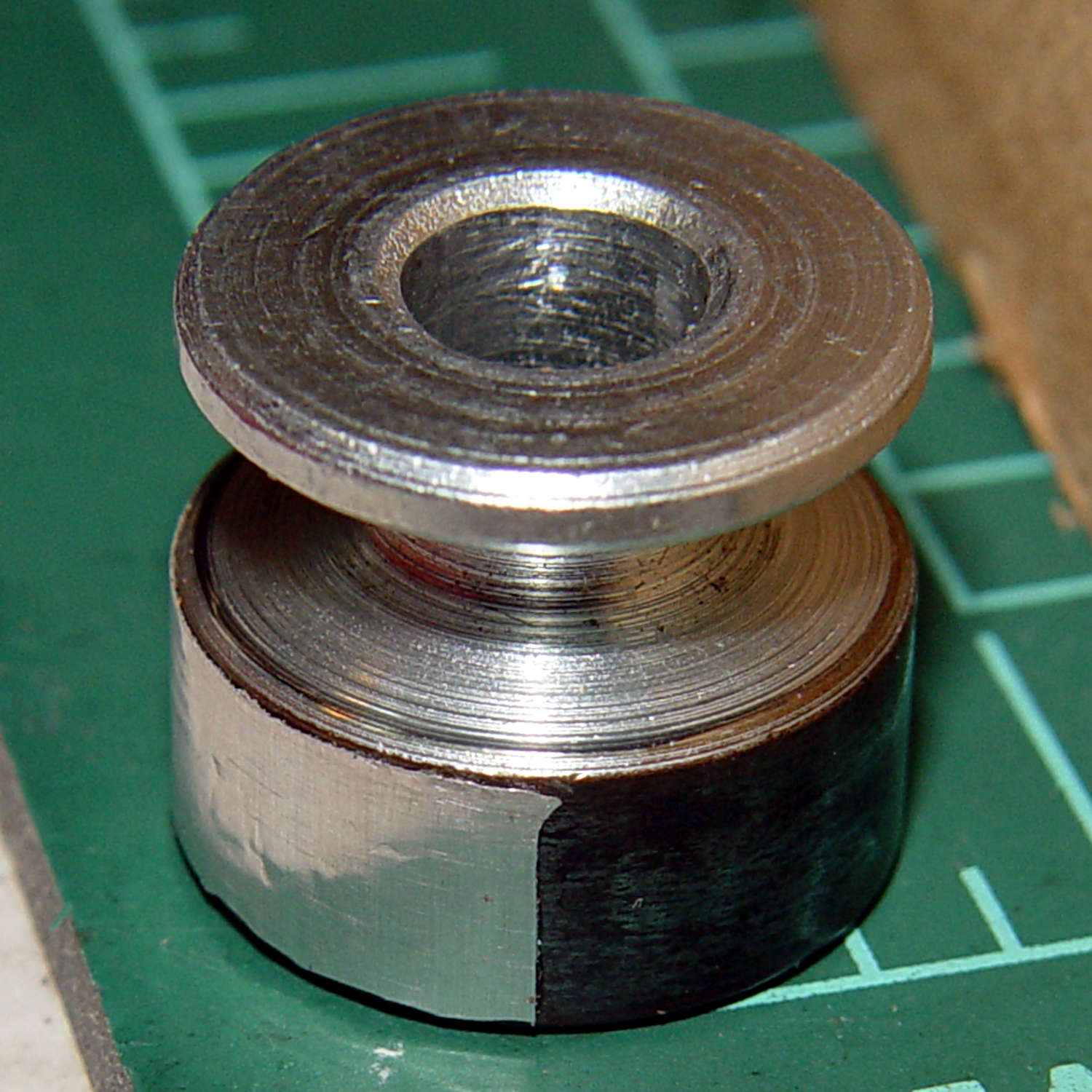
Apply stainless steel tape around half the circumference
Burnish flat
Which looks pretty good:
Kenmore 158 motor pulley – black-silver
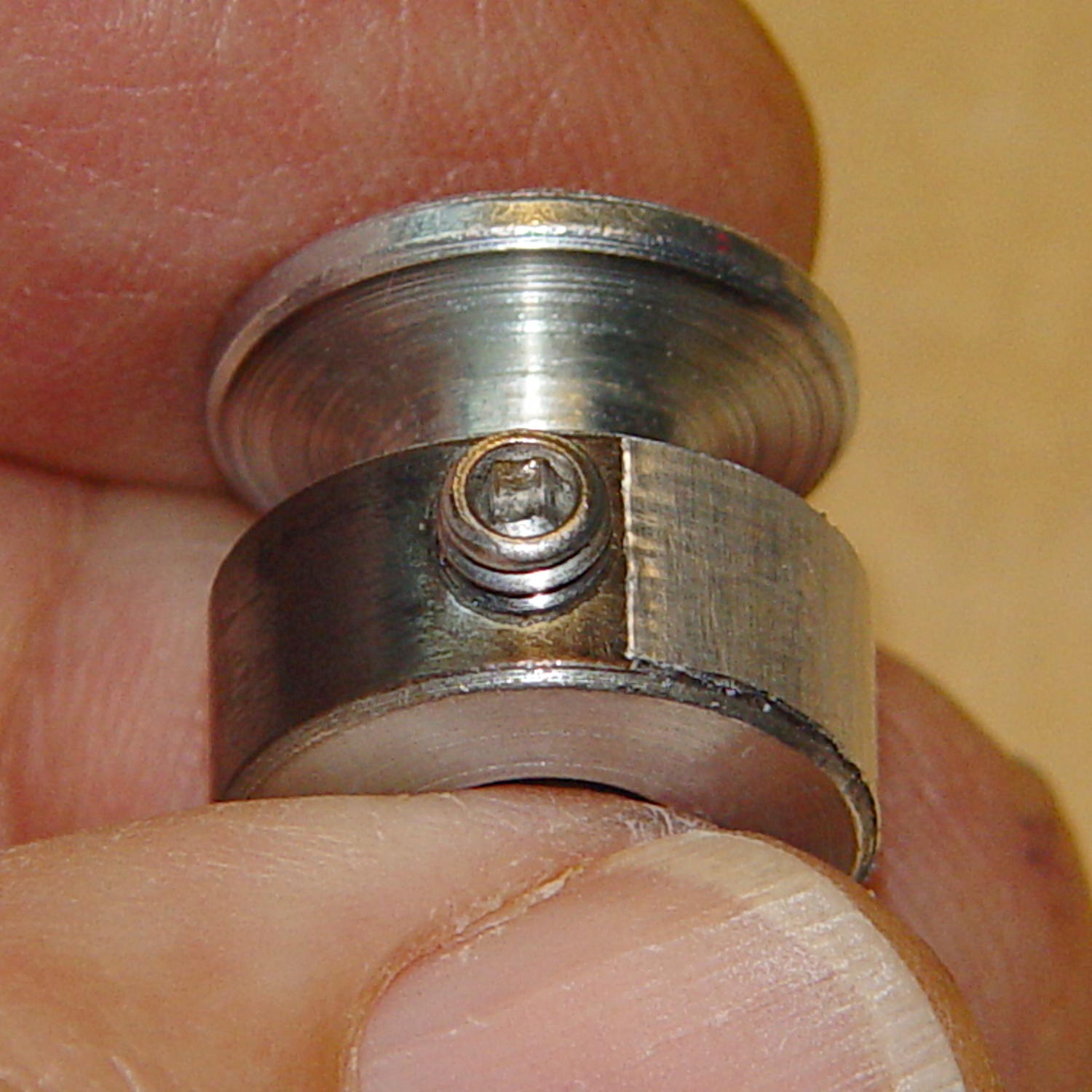
The stainless tape butts up against the setscrew:
Kenmore 158 motor pulley – black-silver at setscrew
Adjusting the sensitivity midway between the point where the output is low (OFF) over the black and high (ON) over the tape seems reasonable.
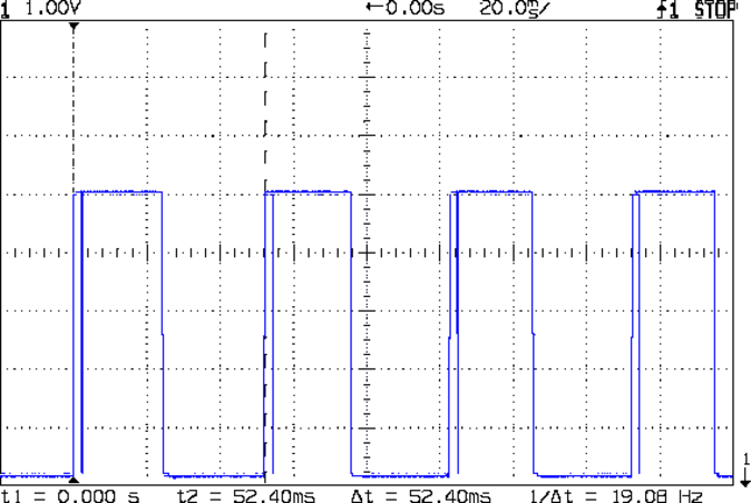
Running at the slowest possible speed produces this pulse train:
Motor sense – min speed
The motor at 19 rev/s = 1140 RPM corresponds to about 2 rev/s of the sewing machine shaft= 2 stitch/s. Slower than, that, the pedal won’t go in simple open-loop mode.
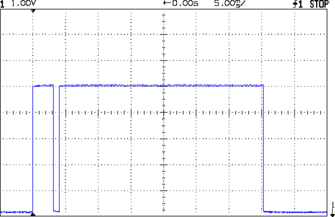
The setscrew causes those “glitches” on the rising edge. They look like this at a faster sweep:
Motor sense – min speed – setscrew
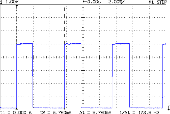
At maximum speed, the setscrew doesn’t show up:
Motor sense – max speed
The motor at 174 rev/s = 10440 RPM would do 1000 stitch/s, but that’s just crazy talk: it runs at that speed with the handwheel clutch disengaged and the motor driving only the bobbin winder. I was holding the machine down with the shaft engaged and all the gimcrackery flailing around during that shot.
The sensor board may have an internal glitch filter, but it’s hard to say: the eBay description has broken links to the circuit documentation.
I could grind the setscrew flush with the pulley OD and cover it with tape, but that seems unreasonable. Fixing the glitch in firmware shouldn’t be too difficult: ignore a rising edge that occurs less than, say, 1/4 of the previous period following the previous edge.
Perhaps buffing half the pulley’s circumference to a reasonable shine (minus the bluing) would eliminate the need for the stainless steel tape.
Iterating the bluing operation / scrubbing with steel wool should produce a darker black, although two passes yields a nice flat black.
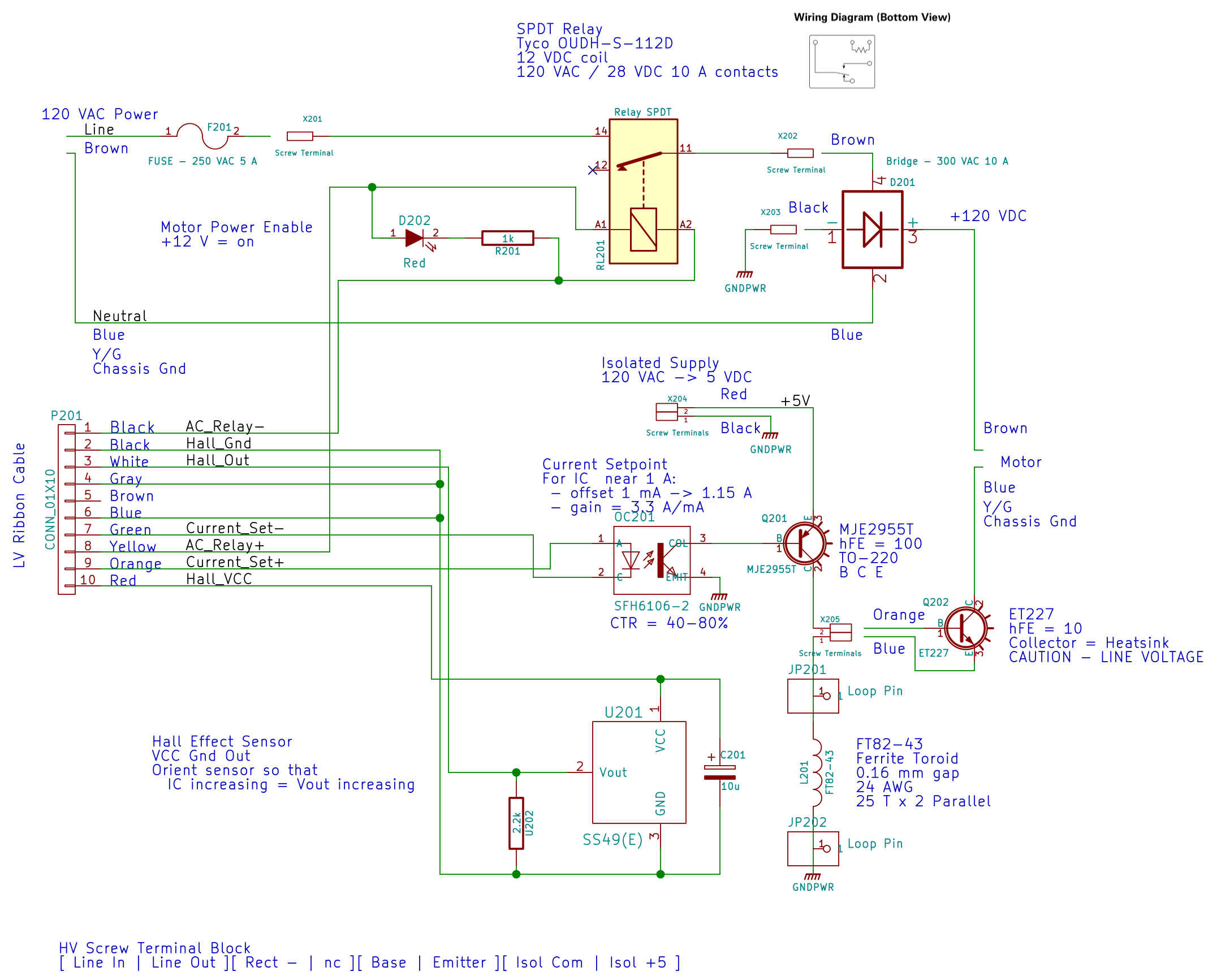
The relay at the top connects the AC hot line to the rest of the circuitry, with a feeble red LED to show when it’s live:
AC Power Interface
The driver lives on the Low Voltage Interface board:
LV Power Interface – AC Relay driver
The GX270’s front-panel hard drive LED now serves to indicate when the AC power goes live.
I’d originally intended to turn the AC on when the Arduino gains control, but after seeing those pictures, I think it’ll remain disabled unless there’s a call for motor motion.
The interlock switch closes when the case opens, grounding the transistor base and disconnecting the AC power.
Of course, you can cheat by simply unplugging the switch, so it’s not failsafe. If you want failsafe, you need a normally closed switch in series with the collector; that’s not what Dell used as a chassis intrusion switch. That’s my story and I’m sticking with it.
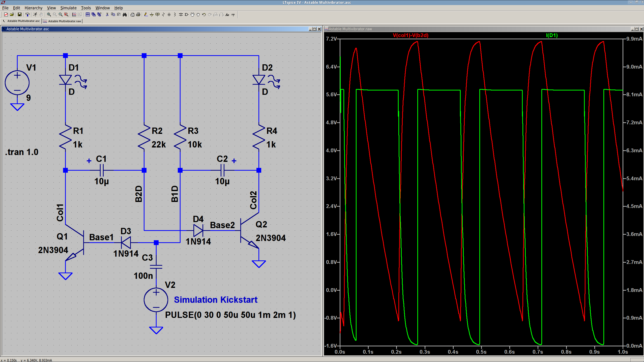
The 10 µF caps scale the output to visible blinkiness. Their polarity may seem backwards, but the red trace in the simulation shows that the net voltage is positive in that direction for nearly the entire cycle. They see only two forward biased junctions in the other direction, so they shouldn’t blow up.
I built it with resistors from the SqWr junk box parts cabinet that were close to the nominal values.
Connecting the transistor base / cap charging resistors to the power supply, rather than the LEDs, gets rid of the tiny current when the LEDs should be off.
The cap-and-pulse-generator dingus on the bottom kickstarts the simulation; it doesn’t have any physical significance.
Memo to Self: Build one with a pair of ET227 transistors and some 100 W tungsten bulbs…