Another switch for the temporary basement LED light strips failed the same way:

As always with such things, I suspect the only reason it has a UL mark on the back is because somebody else hasn’t missed theirs yet.
So I got a three-pack of inline switches with cute little indicator lights and set about replacing all of them:

These switches carry absolutely no regulatory approval markings, although they do claim to carry 10 A at 250 V, which I take with another load of salt.
At least here in the US-of-A, a 240 VAC outlet has two “hot” wires carrying 120 VAC 180° out of phase, which means both conductors must be switched. Despite the voltage rating, only the L path goes through the clicky switch, with the N path along a strap just below the switch toggle. Using it on a 240 VAC circuit will kill you stone cold dead should you assume whatever it controls is turned off.
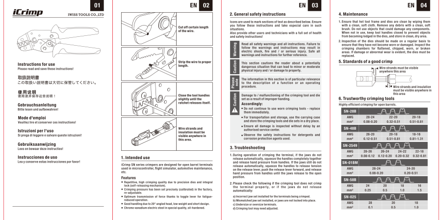
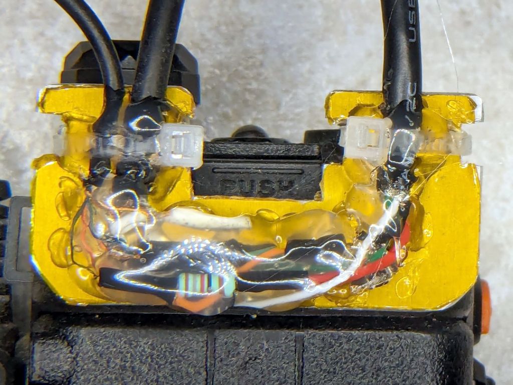
I secured the Line and Neutral conductors with crimp connectors, rather than just wrapping the 20 AWG wires around the screw terminals, because the case halves join without perimeter nesting: a bare millimeter of air in the gap between the halves separates the terminals from my fingers. A layer of good electrical tape on each side improved that situation, but not by much.
The complete lack of strain relief clamping on the cords prompted me to route the wires around the screw bosses. After a function check, squirts of hot melt glue anchored the two cords somewhat better.
Aaaaand I secured that loose strap on the right with an (identical to the others!) screw from the Tray o’ Random Screws. The other switches had both screws installed, so this one must have been a QC escape.
They suffice for the purpose, but … caveat emptor!