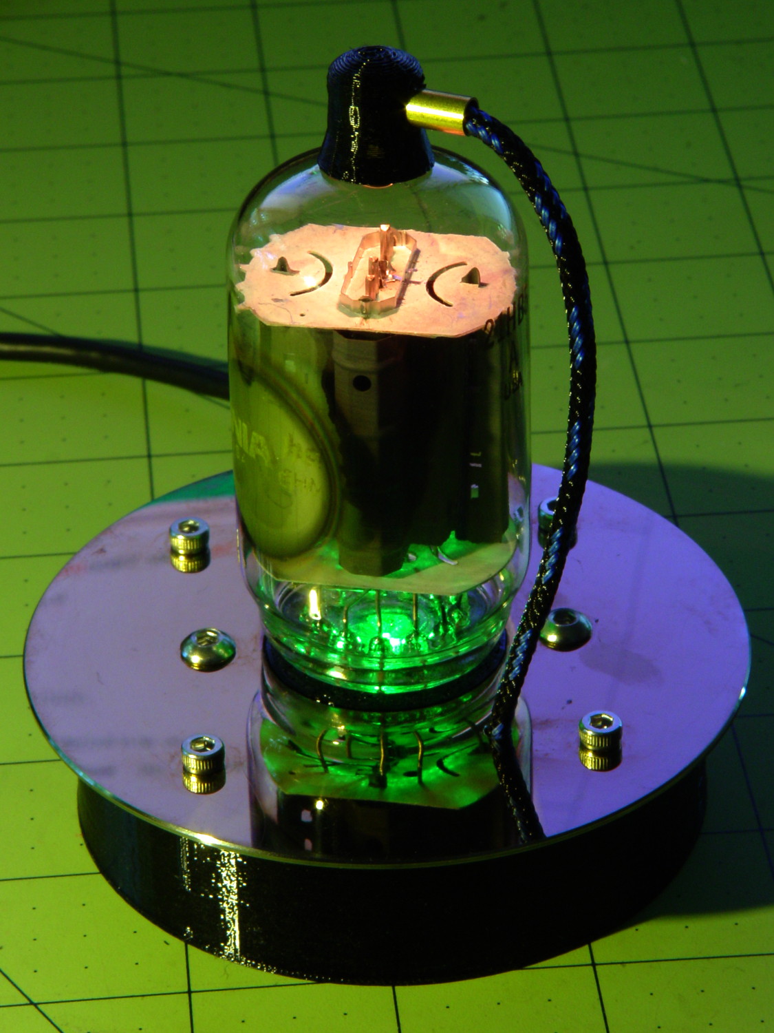
The Smell of Molten Projects in the Morning

Ed Nisley's Blog: Shop notes, electronics, firmware, machinery, 3D printing, laser cuttery, and curiosities. Contents: 100% human thinking, 0% AI slop.

Category: Electronics Workbench

Electrical & Electronic gadgets

  • Rewiring a Baofeng Battery Eliminator

    An aftermarket “battery eliminator” for Baofeng UV-5R radios costs under seven bucks delivered:

    Baofeng Battery Eliminator - overview
    Baofeng Battery Eliminator – overview

    That label seemed … odd:

    Baofeng Battery Eliminator - Li-ion Label
    Baofeng Battery Eliminator – Li-ion Label

    The OEM battery, tucked inside a case that’s for all intents and purposes identical to this one, sports an 1800 mA·h rating that I regarded as mmmm optimistic; I’d expect maybe 1000 mA·h, tops. From what I can tell, the 3800 mA·h label should go on an extended-capacity “big” battery that wraps around the bottom of the radio. Maybe the factory produced a pallet of mis-labeled small packs that they couldn’t fob off on actual customers with a straight face and couldn’t justify the labor to peel-and-stick the proper labels.

    Anyhow, it’s not a battery.

    The circuitry inside shows considerably more fit & finish than I expected:

    Baofeng Battery Eliminator - interior
    Baofeng Battery Eliminator – interior

    It’s not clear how effective that heatsink could be, given that it’s trapped inside a compact plastic enclosure snugged against the radio’s metal chassis, but it’s a nice touch. Two layers of foam tape anchor the terminals at the top and hold the heatsink / LM7808-class TO-220 regulator in place.

    Although I wanted the DC input to come from the side, rather than the bottom, so the radio could stand up, the pack simply isn’t thick enough to accommodate the jack in that orientation. I drilled out the existing wire hole to fit a coaxial power plug and deployed my own foam tape:

    Baofeng Battery Eliminator - rewired interior
    Baofeng Battery Eliminator – rewired interior

    Replacing the foam tape at the top holds the bent-brass (?) terminals in more-or-less the proper orientation, with Genuine 3M / Scotch Plaid adding a festive touch. A groove in the other half of the shell captures the free ends of those terminals, so they’re not flopping around in mid-air.

    The jack fits an old-school 7.5 V transformer wall wart that produces 11 V open-circuit. It’s probably still a bit too high with the UV-5R’s minimal receive-only load, but I refuse to worry.

    Now KE4ZNU-10 won’t become a lithium fire in the attic stairwell…

    While I had the hood up, I used Chirp to gut the radio’s stored frequencies / channels / memories and set 144.39 in Memory 0 as the only non-zero value. With a bit of luck, that will prevent it from crashing and jamming a randomly chosen frequency outside the amateur bands…

  • More Cheap eBay Hardware Failures

    Data points…

    Another knockoff Neopixel failed in the usual way, after a few days of operation: the first W2812B chip in the string gave off intermittent and random flashes of pure primary colors, the second was dead in the water. Replacing the first chip with Yet Another Knockoff from the same lot restored the tube to good health.

    Some oscilloscope probing revealed a pooched serial data output with no active pullup, so the output data rarely exceeded VCC/2 and generally wouldn’t be accepted by the downstream W2812B. Nothing to show for it, as I couldn’t be bothered to upload a scope shot. Maybe next time.

    One of the counterfeit FTDI USB-to-serial adapters in another tube base failed after a few weeks of operation, with symptoms ranging from hangs while downloading the Arduino program to readback verify mismatches. Replacing the failed adapter and the knockoff Arduino Pro Mini with a knockoff Arduino Nano (using a CH340 USB interface, presumably not a counterfeit) from a recently arrived envelope restored that tube to good health.

    All in all, those knockoff Neopixels have been a constant source of amusement; worth every penny just for the privilege of holding them up for ridicule. The “genuine” FTDI chips weren’t much of a surprise, but I am mildly surprised they work so poorly.

  • Vacuum Tube LEDs: Octal Tube Base Drilling

    Clamping the octal tube into the Sherline let me set the XY=0 origin to the center of the base with the laser dot (visible near the front):

    Octal tube clamped on Sherline mill
    Octal tube clamped on Sherline mill

    Find the edges, touch off the half the 32.2 mm diameter, then align the drill at XY=0 directly over the exposed evacuation tip:

    Octal Tube - drill alignment
    Octal Tube – drill alignment

    Make a very shallow cut to verify the alignment:

    Octal Tube - drill first touch
    Octal Tube – drill first touch

    Just inside the scuffed ring from the drill, you can see the fractured ring where the original one-piece Bakelite spigot / key / post broke off.

    Then extract the drill from the chuck, file more relief behind the cutting edges so they actually cut, re-chuck, and continue the mission:

    Octal Tube - drilling
    Octal Tube – drilling

    Pick a nice Bakelite ring out of the drill:

    Octal Tube - drilled ring
    Octal Tube – drilled ring

    And eventually you can see all the way to the glass envelope:

    Octal Tube - base opening
    Octal Tube – base opening

    The (knockoff) Neopixel LED sits directly below the evacuation tip and is about the same diameter, so much of that enlarged opening will be in shadow. Despite that, the tube does seem noticeably brighter:

    Octal Tube - drilled base opening
    Octal Tube – drilled base opening

    Drilling that tube was so harrowing that I can’t imagine similar surgery on an intact octal base.

    Perhaps just slicing off the tip of the Bakelite spigot and gluing a single very bright red/orange LED in place, rather using than a (knockoff) Neopixel a few millimeters away, will suffice.

    Or just give up, top-light these tubes, and move on?

  • Vacuum Tube LEDs: Miniature 7-pin Tubes With a Bottom Shield

    Apart from the Bakelite bases on octal tubes, I figured there should be no problem shining a light up through the glass envelope. Come to find out that some of the tubes with Miniature 7 bases have an electrostatic shield (?) across the bottom that pretty well blocks the light.

    This 6BJ6 has a neatly trimmed octagon:

    6BJ6 - octagon shield
    6BJ6 – octagon shield

    The shield plate, if that’s what it is, doesn’t have a standardized shape. This 6CB6 sports a simple square:

    6CB6 Square Shield
    6CB6 Square Shield

    The Box o’ Hollow State Electronics contains one 6BE6 tube (a heptode with five grids connected to four pins) without a shield:

    6BE6 - Clear base
    6BE6 – Clear base

    Yeah, those pins are rather grotendous.

    And another 6BE6 with a semitransparent smudge not connected to anything else; it would look accidental if it weren’t inside the tube:

    6BE6 - Tinted Base
    6BE6 – Tinted Base

    All the shielded tubes are pentodes, for whatever difference that makes.

    These tubes may be a bit too small compared to the hard drive platters; Novals will work just fine for my simple purposes.

  • Vacuum Tube LEDs: Fully Dressed 21HB5A

    Black PETG definitely looks better than cyan for this job:

    21HB5A - Black PETG base - flash
    21HB5A – Black PETG base – flash

    Holding the plate cap to the tube with a thin ring of opaque epoxy cuts down on the glare under its edge:

    21HB5A - Black PETG base - cyan phase
    21HB5A – Black PETG base – cyan phase

    Fire in the bottle!

    21HB5A - Black PETG fittings - punched drive platter - purple phase
    21HB5A – Black PETG fittings – punched drive platter – purple phase

    It’s still running basically the same Arduino code as before, but I have some ideas about that

  • Vacuum Tube LEDs: Hard Drive Platter Base

    Stainless steel socket head and button head screws add a certain techie charm to the hard drive platter mirroring the Noval tube:

    Noval - Black PETG base - magenta phase
    Noval – Black PETG base – magenta phase

    Black PETG, rather than cyan or natural filament, suppresses the socket’s glow and emphasizes the tube’s internal lighting:

    Noval tube on platter - button-head screws
    Noval tube on platter – button-head screws

    The base puts the USB-to-serial adapter on the floor and stands the Pro Mini against a flat on the far wall:

    Noval tube socket and base - interior layout
    Noval tube socket and base – interior layout

    A notch for the cable seems like a useful addition subtraction to the socket, because that cable tie just doesn’t look right. I used 4 mm threaded inserts, as those button head screws looked better.

    The solid model looks like you’d expect:

    Vacuum Tube Lights - hard drive platter base - solid model
    Vacuum Tube Lights – hard drive platter base – solid model

    Those are 3 mm threaded inserts, again to get the right head size screw on the platter.

    The height of the base depends on the size of the socket, with the model maintaining a bit of clearance above the USB adapter. The OD depends on the platter OD, with a fixed overhang, and the insert BCD depends on the OD / insert OD / base wall thickness.

    Although I’m using an Arduino Pro Mini and a separate USB-to-serial adapter, a (knockoff) Arduino Nano would be better and cheaper, although the SMD parts on the Nano’s bottom surface make it a bit thicker and less suitable for foam-tape mounting.

    I drilled the platter using manual CNC:

    Hard drive platter - Noval base drilling
    Hard drive platter – Noval base drilling

    After centering the origin on the platter hole, the hole positions (for a 71 mm BCD) use LinuxCNC’s polar notation:

    g0 @[71/2]^45
    g0 @[71/2]^[45+90]
    g0 @[71/2]^[45+180]
    g0 @[71/2]^-45
    

    I used the Joggy Thing for manual drilling after each move; that’s easier than figuring out the appropriate g81 feed & speed.

    The 3D printed base still looks a bit chintzy compared with the platter, but it’s coming along.

    The OpenSCAD source code as a GitHub Gist:

    // Vacuum Tube LED Lights
    // Ed Nisley KE4ZNU February … September 2016
    Layout = "PlatterBase"; // Cap LampBase USBPort Bushings
    // Socket(s) (Build)FinCap Platter[Base|Fixture]
    DefaultSocket = "Noval";
    Section = false; // cross-section the object
    Support = true;
    //- Extrusion parameters must match reality!
    ThreadThick = 0.25;
    ThreadWidth = 0.40;
    HoleWindage = 0.2;
    Protrusion = 0.1; // make holes end cleanly
    inch = 25.4;
    function IntegerMultiple(Size,Unit) = Unit * ceil(Size / Unit);
    //———————-
    // Dimensions
    // https://en.wikipedia.org/wiki/Tube_socket#Summary_of_Base_Details
    // punch & screw OC modified for drive platter chassis plate
    // platter = 25 mm ID
    // CD = 15 mm ID with raised ring at 37 mm, needs screw head clearance
    T_NAME = 0; // common name
    T_NUMPINS = 1; // total, with no allowance for keying
    T_PINBCD = 2; // tube pin circle diameter
    T_PINOD = 3; // … diameter
    T_PINLEN = 4; // … length (must also clear evacuation tip / spigot)
    T_HOLEOD = 5; // nominal panel hole from various sources
    T_PUNCHOD = 6; // panel hole optimized for inch-size Greenlee punches
    T_TUBEOD = 7; // envelope or base diameter
    T_PIPEOD = 8; // light pipe from LED to tube base (clear evac tip / spigot)
    T_SCREWOC = 9; // mounting screw holes
    // Name pins BCD dia length hole punch tube pipe screw
    TubeData = [
    ["Mini7", 8, 9.53, 1.016, 7.0, 16.0, 25.0, 18.0, 5.0, 35.0], // punch 11/16, screw 22.5 OC
    ["Octal", 8, 17.45, 2.36, 10.0, 36.2, (8 + 1)/8 * inch, 32.0, 11.5, 47.0], // screw 39.0 OC
    ["Noval", 10, 11.89, 1.1016, 7.0, 22.0, 25.0 , 21.0, 7.5, 35.0], // punch 7/8, screw 28.0 OC
    ["Magnoval", 10, 17.45, 1.27, 9.0, 29.7, (4 + 1)/4 * inch, 46.0, 12.4, 38.2], // similar to Novar
    ["Duodecar", 13, 19.10, 1.05, 9.0, 32.0, (4 + 1)/4 * inch, 38.0, 12.5, 47.0], // screw 39.0 OC
    ];
    ID = 0;
    OD = 1;
    LENGTH = 2;
    Pixel = [7.0,10.0,3.0]; // ID = contact patch, OD = PCB dia, LENGTH = overall thickness
    SocketNut = // socket mounting: threaded insert or nut recess
    // [3.5,5.2,7.2] // 6-32 insert
    [4.0,6.0,5.9] // 4 mm short insert
    ;
    NutSides = 8;
    SocketShim = 2*ThreadThick; // between pin holes and pixel top
    SocketFlange = 1.5; // rim around socket below punchout
    PanelThick = 1.5; // socket extension through punchout
    FinCutterOD = 1/8 * inch;
    FinCapSize = [(Pixel[OD] + 2*FinCutterOD),30.0,(10.0 + 2*Pixel[LENGTH])];
    USBPCB =
    // [28,16,6.5] // small Sparkfun knockoff
    [36,18 + 1,5.8 + 0.4] // Deek-Robot fake FTDI with ISP header
    ;
    Platter = [25.0,95.0,1.26]; // hard drive platter dimensions
    //———————-
    // Useful routines
    module PolyCyl(Dia,Height,ForceSides=0) { // based on nophead's polyholes
    Sides = (ForceSides != 0) ? ForceSides : (ceil(Dia) + 2);
    FixDia = Dia / cos(180/Sides);
    cylinder(d=(FixDia + HoleWindage),h=Height,$fn=Sides);
    }
    //———————-
    // Tube cap
    CapTube = [4.0,3/16 * inch,10.0]; // brass tube for flying lead to cap LED
    CapSize = [Pixel[ID],(Pixel[OD] + 2.0),(CapTube[OD] + 2*Pixel[LENGTH])];
    CapSides = 8*4;
    module Cap() {
    difference() {
    union() {
    cylinder(d=CapSize[OD],h=(CapSize[LENGTH]),$fn=CapSides); // main cap body
    translate([0,0,CapSize[LENGTH]]) // rounded top
    scale([1.0,1.0,0.65])
    sphere(d=CapSize[OD]/cos(180/CapSides),$fn=CapSides); // cos() fixes slight undersize vs cylinder
    cylinder(d1=(CapSize[OD] + 2*3*ThreadWidth),d2=CapSize[OD],h=1.5*Pixel[LENGTH],$fn=CapSides); // skirt
    }
    translate([0,0,-Protrusion]) // bore for wiring to LED
    PolyCyl(CapSize[ID],(CapSize[LENGTH] + 3*ThreadThick + Protrusion),CapSides);
    translate([0,0,-Protrusion]) // PCB recess with clearance for tube dome
    PolyCyl(Pixel[OD],(1.5*Pixel[LENGTH] + Protrusion),CapSides);
    translate([0,0,(1.5*Pixel[LENGTH] – Protrusion)]) // small step + cone to retain PCB
    cylinder(d1=(Pixel[OD]/cos(180/CapSides) + HoleWindage),d2=Pixel[ID],h=(Pixel[LENGTH] + Protrusion),$fn=CapSides);
    translate([0,0,(CapSize[LENGTH] – CapTube[OD]/(2*cos(180/8)))]) // hole for brass tube holding wire loom
    rotate([90,0,0]) rotate(180/8)
    PolyCyl(CapTube[OD],CapSize[OD],8);
    }
    }
    //———————-
    // Heatsink tube cap
    module FinCap() {
    CableOD = 3.5; // cable + braid diameter
    BulbOD = 3.75 * inch; // bulb OD; use 10 inches for flat
    echo(str("Fin Cutter: ",FinCutterOD));
    FinSides = 2*4;
    BulbRadius = BulbOD / 2;
    BulbDepth = BulbRadius – sqrt(pow(BulbRadius,2) – pow(FinCapSize[OD],2)/4);
    echo(str("Bulb OD: ",BulbOD," recess: ",BulbDepth));
    NumFins = floor(PI*FinCapSize[ID] / (2*FinCutterOD));
    FinAngle = 360 / NumFins;
    echo(str("NumFins: ",NumFins," angle: ",FinAngle," deg"));
    difference() {
    union() {
    cylinder(d=FinCapSize[ID],h=FinCapSize[LENGTH],$fn=2*NumFins); // main body
    for (i = [0:NumFins – 1]) // fins
    rotate(i * FinAngle)
    hull() {
    translate([FinCapSize[ID]/2,0,0])
    rotate(180/FinSides)
    cylinder(d=FinCutterOD,h=FinCapSize[LENGTH],$fn=FinSides);
    translate([(FinCapSize[OD] – FinCutterOD)/2,0,0])
    rotate(180/FinSides)
    cylinder(d=FinCutterOD,h=FinCapSize[LENGTH],$fn=FinSides);
    }
    rotate(FinAngle/2) // cable entry boss
    translate([FinCapSize[ID]/2,0,FinCapSize[LENGTH]/2])
    cube([FinCapSize[OD]/4,FinCapSize[OD]/4,FinCapSize[LENGTH]],center=true);
    }
    for (i = [1:NumFins – 1]) // fin inner gullets, omit cable entry side
    rotate(i * FinAngle + FinAngle/2) // joint isn't quite perfect, but OK
    translate([FinCapSize[ID]/2,0,-Protrusion])
    rotate(0*180/FinSides)
    cylinder(d=FinCutterOD/cos(180/FinSides),h=(FinCapSize[LENGTH] + 2*Protrusion),$fn=FinSides);
    translate([0,0,-Protrusion]) // PCB recess
    PolyCyl(Pixel[OD],(1.5*Pixel[LENGTH] + Protrusion),FinSides);
    PolyCyl(Pixel[ID],(FinCapSize[LENGTH] – 3*ThreadThick),FinSides); // bore for LED wiring
    translate([0,0,(FinCapSize[LENGTH] – 3*ThreadThick – 2*CableOD/(2*cos(180/8)))]) // cable inlet
    rotate(FinAngle/2) rotate([0,90,0]) rotate(180/8)
    PolyCyl(CableOD,FinCapSize[OD],8);
    if (BulbOD <= 10.0 * inch) // curve for top of bulb
    translate([0,0,-(BulbRadius – BulbDepth + 2*ThreadThick)]) // … slightly flatten tips
    sphere(d=BulbOD,$fn=16*FinSides);
    }
    }
    //———————-
    // Aperture for USB-to-serial adapter snout
    // These are all magic numbers, of course
    module USBPort() {
    translate([0,USBPCB[0]])
    rotate([90,0,0])
    linear_extrude(height=USBPCB[0])
    polygon(points=[
    [0,0],
    [USBPCB[1]/2,0],
    [USBPCB[1]/2,0.5*USBPCB[2]],
    [USBPCB[1]/3,USBPCB[2]],
    [-USBPCB[1]/3,USBPCB[2]],
    [-USBPCB[1]/2,0.5*USBPCB[2]],
    [-USBPCB[1]/2,0],
    ]);
    }
    //———————-
    // Box for Leviton ceramic lamp base
    module LampBase() {
    Insert = [3.5,5.2,7.2]; // 6-32 brass insert to match standard electrical screws
    Bottom = 3.0;
    Base = [4.0*inch,4.5*inch,20.0 + Bottom];
    Sides = 12*4;
    Retainer = [3.5,11.0,1.0]; // flat fiber washer holding lamp base screws in place
    StudSides = 8;
    StudOC = 3.5 * inch;
    Stud = [Insert[OD], // insert for socket screws
    min(15.0,1.5*(Base[ID] – StudOC)/cos(180/StudSides)), // OD = big enough to merge with walls
    (Base[LENGTH] – Retainer[LENGTH])]; // leave room for retainer
    union() {
    difference() {
    rotate(180/Sides)
    cylinder(d=Base[OD],h=Base[LENGTH],$fn=Sides);
    rotate(180/Sides)
    translate([0,0,Bottom])
    cylinder(d=Base[ID],h=Base[LENGTH],$fn=Sides);
    translate([0,-Base[OD]/2,Bottom + 1.2]) // mount on double-sided foam tape
    rotate(0)
    USBPort();
    }
    for (i = [-1,1])
    translate([i*StudOC/2,0,0])
    rotate(180/StudSides)
    difference() {
    cylinder(d=Stud[OD],h=Stud[LENGTH],$fn=StudSides);
    translate([0,0,Bottom])
    PolyCyl(Stud[ID],(Stud[LENGTH] – (Bottom – Protrusion)),6);
    }
    }
    }
    //———————-
    // Base for hard drive platters
    module PlatterBase(TubeName = DefaultSocket) {
    PCB =
    [36,18,3] // Arduino Pro Mini
    ;
    Tube = search([TubeName],TubeData,1,0)[0];
    SocketHeight = Pixel[LENGTH] + SocketShim + TubeData[Tube][T_PINLEN] – PanelThick;
    echo(str("Base for ",TubeData[Tube][0]," socket"));
    Overhang = 5.5; // platter overhangs base by this much
    Bottom = 4*ThreadThick;
    Base = [(Platter[OD] – 3*Overhang), // smaller than 3.5 inch Sch 40 PVC pipe…
    (Platter[OD] – 2*Overhang),
    2.0 + max(PCB[1],(2.0 + SocketHeight + USBPCB[2])) + Bottom];
    Sides = 24*4;
    echo(str(" Height: ",Base[2]," mm"));
    Insert = // platter mounting: threaded insert or nut recess
    // [3.5,5.2,7.2] // 6-32 insert
    [3.9,5.0,8.0] // 3 mm – long insert
    ;
    NumStuds = 4;
    StudSides = 8;
    Stud = [Insert[OD], // insert for socket screws
    2*Insert[OD], // OD = big enough to merge with walls
    Base[LENGTH]]; // leave room for retainer
    StudBCD = floor(Base[ID] – Stud[OD] + (Stud[OD] – Stud[ID])/2);
    echo(str("Platter screw BCD: ",StudBCD," mm"));
    PCBInset = Base[ID]/2 – sqrt(pow(Base[ID]/2,2) – pow(PCB[0],2)/4);
    union() {
    difference() {
    rotate(180/Sides)
    cylinder(d=Base[OD],h=Base[LENGTH],$fn=Sides);
    rotate(180/Sides)
    translate([0,0,Bottom])
    cylinder(d=Base[ID],h=Base[LENGTH],$fn=Sides);
    translate([0,-Base[OD]/2,Bottom + 1.2]) // mount PCB on foam tape
    rotate(0)
    USBPort();
    }
    for (a = [0:(NumStuds – 1)]) // platter mounting studs
    rotate(180/NumStuds + a*360/(NumStuds))
    translate([StudBCD/2,0,0])
    rotate(180/StudSides)
    difference() {
    cylinder(d=Stud[OD],h=Stud[LENGTH],$fn=2*StudSides);
    translate([0,0,Bottom])
    PolyCyl(Stud[ID],(Stud[LENGTH] – (Bottom – Protrusion)),StudSides);
    }
    intersection() { // microcontroller PCB mounting plate
    rotate(180/Sides)
    cylinder(d=Base[OD],h=Base[LENGTH],$fn=Sides);
    translate([-PCB[0]/2,(Base[ID]/2 – PCBInset),0])
    cube([PCB[0],Base[OD]/2,Base[LENGTH]],center=false);
    }
    difference() {
    intersection() { // totally ad-hoc bridge around USB opening
    rotate(180/Sides)
    cylinder(d=Base[OD],h=Base[LENGTH],$fn=Sides);
    translate([-1.25*USBPCB[1]/2,-(Base[ID]/2),0])
    cube([1.25*USBPCB[1],2.0,Base[LENGTH]],center=false);
    }
    translate([0,-Base[OD]/2,Bottom + 1.2]) // mount PCB on foam tape
    rotate(0)
    USBPort();
    }
    }
    }
    //———————-
    // Drilling fixture for disk platters
    module PlatterFixture() {
    StudOC = [1.16*inch,1.16*inch]; // Sherline tooling plate screw spacing
    StudClear = 5.0;
    BasePlate = [(20 + StudOC[0]*ceil(Platter[OD] / StudOC[0])),(Platter[OD] + 10),7.0];
    PlateRound = 10.0; // corner radius
    difference() {
    hull() // basic block
    for (i=[-1,1], j=[-1,1])
    translate([i*(BasePlate[0]/2 – PlateRound),j*(BasePlate[1]/2 – PlateRound),0])
    cylinder(r=PlateRound,h=BasePlate[2],$fn=4*4);
    for (i=[-1:1], j=[-1:1]) // index marks
    translate([i*100/2,j*100/2,BasePlate[2] – 2*ThreadThick])
    cylinder(d=1.5,h=1,$fn=6);
    for (i=[-1,1], j=[-1,0,1]) // holes for tooling plate studs
    translate([i*StudOC[0]*ceil(Platter[OD] / StudOC[0])/2,j*StudOC[0],-Protrusion])
    PolyCyl(StudClear,BasePlate[2] + 2*Protrusion,6);
    translate([0,0,-Protrusion]) // center clamp hole
    PolyCyl(StudClear,BasePlate[2] + 2*Protrusion,6);
    translate([0,0,BasePlate[2] – Platter[LENGTH]]) // disk locating recess
    linear_extrude(height=(Platter[LENGTH] + Protrusion),convexity=2)
    difference() {
    circle(d=(Platter[OD] + 1),$fn=8*4);
    circle(d=Platter[ID],$fn=8*4);
    }
    translate([0,0,BasePlate[2] – 4.0]) // drilling recess
    linear_extrude(height=(4.0 + Protrusion),convexity=2)
    difference() {
    circle(d=(Platter[OD] – 10),$fn=8*4);
    circle(d=(Platter[ID] + 10),$fn=8*4);
    }
    }
    }
    //———————-
    // Tube Socket
    module Socket(Name = DefaultSocket) {
    NumSides = 6*4;
    Tube = search([Name],TubeData,1,0)[0];
    echo(str("Building ",TubeData[Tube][0]," socket"));
    echo(str(" Punch: ",TubeData[Tube][T_PUNCHOD]," mm = ",TubeData[Tube][T_PUNCHOD]/inch," inch"));
    echo(str(" Screws: ",TubeData[Tube][T_SCREWOC]," mm =",TubeData[Tube][T_SCREWOC]/inch," inch OC"));
    OAH = Pixel[LENGTH] + SocketShim + TubeData[Tube][T_PINLEN];
    BaseHeight = OAH – PanelThick;
    difference() {
    union() {
    linear_extrude(height=BaseHeight) // base outline
    hull() {
    circle(d=(TubeData[Tube][T_PUNCHOD] + 2*SocketFlange),$fn=NumSides);
    for (i=[-1,1])
    translate([i*TubeData[Tube][T_SCREWOC]/2,0])
    circle(d=2.0*SocketNut[OD],$fn=NumSides);
    }
    cylinder(d=TubeData[Tube][T_PUNCHOD],h=OAH,$fn=NumSides); // boss in chassis punch hole
    }
    for (i=[0:(TubeData[Tube][T_NUMPINS] – 1)]) // tube pins
    rotate(i*360/TubeData[Tube][T_NUMPINS])
    translate([TubeData[Tube][T_PINBCD]/2,0,(OAH – TubeData[Tube][T_PINLEN])])
    rotate(180/4)
    PolyCyl(TubeData[Tube][T_PINOD],(TubeData[Tube][T_PINLEN] + Protrusion),4);
    for (i=[-1,1]) // mounting screw holes & nut traps / threaded inserts
    translate([i*TubeData[Tube][T_SCREWOC]/2,0,-Protrusion]) {
    PolyCyl(SocketNut[OD],(SocketNut[LENGTH] + Protrusion),NutSides);
    PolyCyl(SocketNut[ID],(OAH + 2*Protrusion),NutSides);
    }
    translate([0,0,-Protrusion]) { // LED recess
    PolyCyl(Pixel[OD],(Pixel[LENGTH] + Protrusion),8);
    }
    translate([0,0,(Pixel[LENGTH] – Protrusion)]) { // light pipe
    rotate(180/TubeData[Tube][T_NUMPINS])
    PolyCyl(TubeData[Tube][T_PIPEOD],(OAH + 2*Protrusion),TubeData[Tube][T_NUMPINS]);
    }
    }
    // Totally ad-hoc support structures …
    if (Support) {
    color("Yellow") {
    for (i=[-1,1]) // nut traps
    translate([i*TubeData[Tube][T_SCREWOC]/2,0,(SocketNut[LENGTH] – ThreadThick)/2])
    for (a=[0:5])
    rotate(a*30 + 15)
    cube([2*ThreadWidth,0.9*SocketNut[OD],(SocketNut[LENGTH] – ThreadThick)],center=true);
    if (Pixel[OD] > TubeData[Tube][T_PIPEOD]) // support pipe only if needed
    translate([0,0,(Pixel[LENGTH] – ThreadThick)/2])
    for (a=[0:7])
    rotate(a*22.5)
    cube([2*ThreadWidth,0.9*Pixel[OD],(Pixel[LENGTH] – ThreadThick)],center=true);
    }
    }
    }
    //———————-
    // Greenlee punch bushings
    module PunchBushing(Name = DefaultSocket) {
    PunchScrew = 9.5;
    BushingThick = 3.0;
    Tube = search([Name],TubeData,1,0)[0];
    echo(str("Building ",TubeData[Tube][0]," bushing"));
    NumSides = 6*4;
    difference() {
    union() {
    cylinder(d=Platter[ID],h=BushingThick,$fn=NumSides);
    cylinder(d=TubeData[Tube][T_PUNCHOD],h=(BushingThick – Platter[LENGTH]),$fn=NumSides);
    }
    translate([0,0,-Protrusion])
    PolyCyl(PunchScrew,5.0,8);
    }
    }
    //———————-
    // Build it
    if (Layout == "Cap") {
    if (Section)
    difference() {
    Cap();
    translate([-CapSize[OD],0,CapSize[LENGTH]])
    cube([2*CapSize[OD],2*CapSize[OD],3*CapSize[LENGTH]],center=true);
    }
    else
    Cap();
    }
    if (Layout == "FinCap") {
    if (Section) render(convexity=5)
    difference() {
    FinCap();
    // translate([0,-FinCapSize[OD],FinCapSize[LENGTH]])
    // cube([2*FinCapSize[OD],2*FinCapSize[OD],3*FinCapSize[LENGTH]],center=true);
    translate([-FinCapSize[OD],0,FinCapSize[LENGTH]])
    cube([2*FinCapSize[OD],2*FinCapSize[OD],3*FinCapSize[LENGTH]],center=true);
    }
    else
    FinCap();
    }
    if (Layout == "BuildFinCap")
    translate([0,0,FinCapSize[LENGTH]])
    rotate([180,0,0])
    FinCap();
    if (Layout == "LampBase")
    LampBase();
    if (Layout == "PlatterBase")
    PlatterBase();
    if (Layout == "PlatterFixture")
    PlatterFixture();
    if (Layout == "USBPort")
    USBPort();
    if (Layout == "Bushings")
    PunchBushing();
    if (Layout == "Socket")
    if (Section) {
    difference() {
    Socket();
    translate([-100/2,0,-Protrusion])
    cube([100,50,50],center=false);
    }
    }
    else
    Socket();
    if (Layout == "Sockets") {
    translate([0,50,0])
    Socket("Mini7");
    translate([0,20,0])
    Socket("Octal");
    translate([0,-15,0])
    Socket("Duodecar");
    translate([0,-50,0])
    Socket("Noval");
    translate([0,-85,0])
    Socket("Magnoval");}
  • Red Oaks Mill APRS iGate: KE4ZNU-10

    APRS coverage of this part of the Mighty Wappinger Creek Valley isn’t very good, particularly for our bicycle radios (low power, crappy antennas, lousy positions), so I finally got around to setting up a receive-only APRS iGate in the attic.

    The whole setup had that lashed-together look:

    KE4ZNU-10 APRS iGate - hardware
    KE4ZNU-10 APRS iGate – hardware

    It’s sitting on the bottom attic stair, at the lower end of a 10 °F/ft gradient, where the Pi 3’s onboard WiFi connects to the router in the basement without any trouble at all.

    After about a week of having it work just fine, I printed a case from Thingiverse:

    KE4ZNU-10 APRS iGate - RPi TNC-Pi case
    KE4ZNU-10 APRS iGate – RPi TNC-Pi case

    Minus the case, however, you can see a TNC-Pi2 kit atop a Raspberry Pi 3, running APRX on a full-up Raspbian Jessie installation:

    RPi TNC-Pi2 stack - heatshrink spacers
    RPi TNC-Pi2 stack – heatshrink spacers

    You must solder the TNC-Pi2 a millimeter or two above the feedthrough header to keep the component leads off the USB jacks. The kit includes a single, slightly too short, aluminum standoff that would be perfectly adequate, but I’m that guy: those are four 18 mm lengths of heatshrink tubing to stabilize the TNC, with the obligatory decorative Kapton tape.

    The only misadventure during kit assembly came from a somewhat misshapen 100 nF ceramic cap:

    Monolithic cap - 100 nF - QC failure
    Monolithic cap – 100 nF – QC failure

    Oddly, it measured pretty close to the others in the kit package. I swapped in a 100 nF ceramic cap from my heap and continued the mission.

    The threaded brass inserts stand in for tiny 4-40 nuts that I don’t have. The case has standoffs with small holes; I drilled-and-tapped 4-40 threads and it’ll be all good.

    The radio, a craptastic Baofeng UV-5R, has a SMA-RP to UHF adapter screwed to the cable from a mobile 2 meter antenna on a random slab of sheet metal on the attic floor. It has Kenwood jack spacing, but, rather than conjure a custom plug, I got a clue and bought a pair of craptastic Baofeng speaker-mics for seven bucks delivered:

    Baofeng speaker-mic wiring
    Baofeng speaker-mic wiring

    For reference, the connections:

    Baofeng speaker-mic cable - pins and colors
    Baofeng speaker-mic cable – pins and colors

    Unsoldering the speaker-mic head and replacing it with a DE-9 connector didn’t take long.

    The radio sits in the charging cradle, which probably isn’t a good idea for the long term. The available Baofeng “battery eliminators” appear to be even more dangerously craptastic than the radios and speaker-mics; I should just gut the cheapest one and use the shell with a better power supply.

    I initially installed Xastir on the Pi, but it’s really too heavyweight for a simple receive-only iGate. APRX omits the fancy map displays and runs perfectly well in a headless installation with a trivial setup configuration.

    There are many descriptions of the fiddling required to convert the Pi 3’s serial port device names back to the Pi / Pi 2 “standard”. I did some of that, but in point of fact none’s required for the TNC-Pi2; use the device name /dev/serial0 and it’s all good:

    <interface>
    serial-device /dev/serial0 19200 8n1 KISS
    callsign $mycall # callsign defaults to $mycall
    tx-ok false # transmitter enable defaults to false
    telem-to-is false # set to 'false' to disable
    </interface>
    

    Because the radio looks out over an RF desert, digipeating won’t be productive and I’ve disabled the PTT. All the received packets go to the Great APRS Database in the Cloud:

    server   noam.aprs2.net
    

    An APRS reception heat map for the last few days in August:

    KE4ZNU-10 Reception Map - 2016-08
    KE4ZNU-10 Reception Map – 2016-08

    The hot red square to the upper left reveals a peephole through the valley walls toward Mary’s Vassar Farms garden plot, where her bike spends a few hours every day. The other hotspots show where roads overlap the creek valley; the skinny purple region between the red endcaps covers the vacant land around the Dutchess County Airport. The scattered purple blocks come from those weird propagation effects that Just Happen; one of the local APRS gurus suggests reflections from airplane traffic far overhead.

    An RPi 3 is way too much computer for an iGate: all four cores run at 0.00 load all day long. On the other paw, it’s $35 and It Just Works.