|
// LED Constant-current driver case |
|
// Ed Nisley – KE4ZNU |
|
// 2026-03-15 |
|
|
|
include <BOSL2/std.scad> |
|
|
|
Layout = "Show"; // [Show,Build,Case,Lid,LidSVG,Switch] |
|
|
|
/* [Hidden] */ |
|
|
|
ThreadThick = 0.2; |
|
HoleWindage = 0.2; |
|
Protrusion = 0.01; |
|
Gap = 5.0; |
|
|
|
WallThick = 1.8; |
|
|
|
TapeThick = 1.5; |
|
|
|
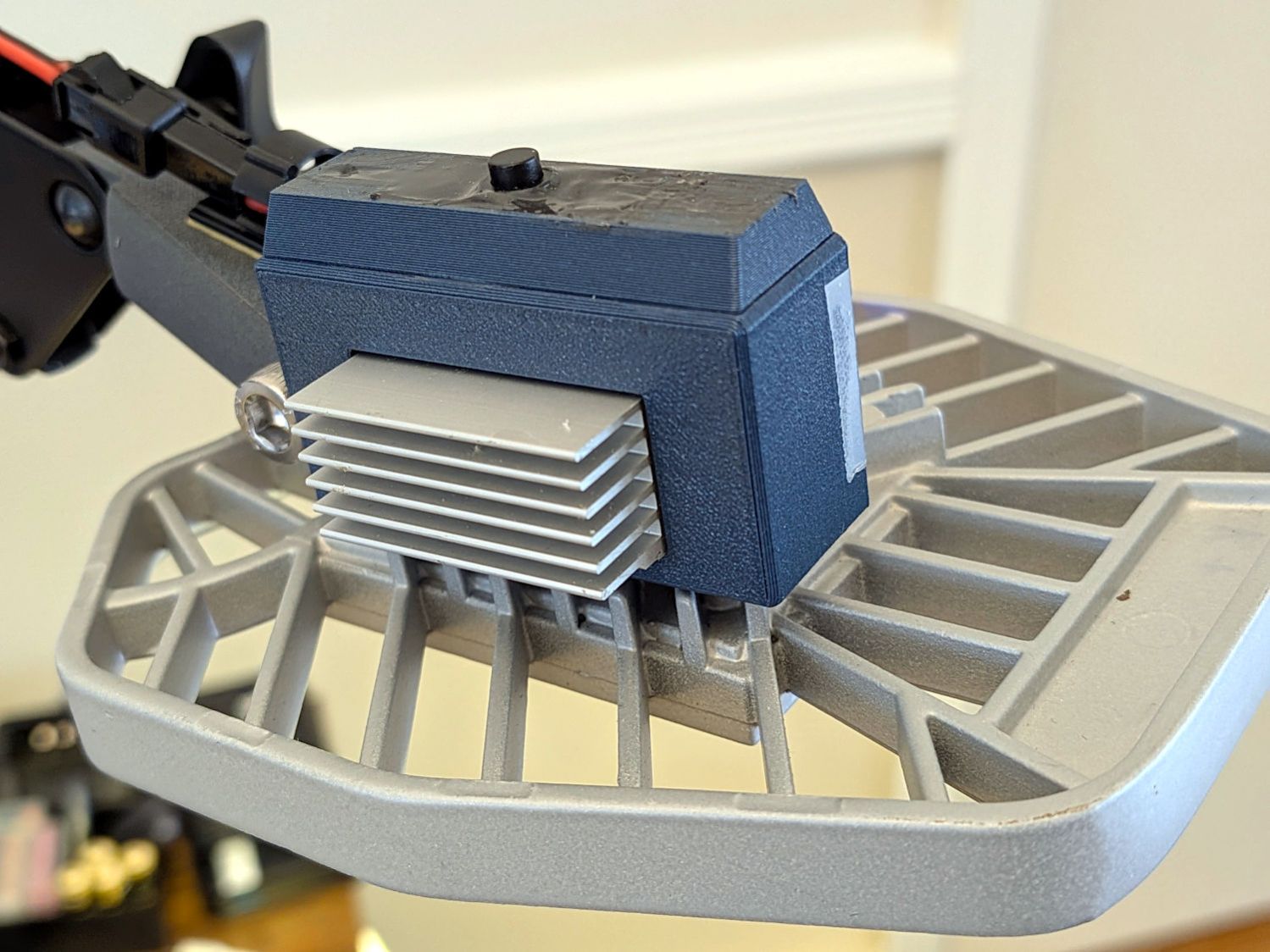
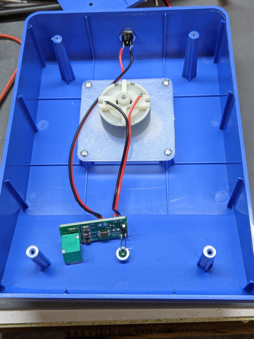
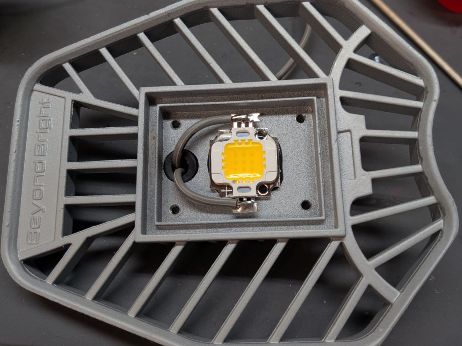
DriverOA = [48.5,13.5 + TapeThick,23.5]; // PCB forward Y, pots along top to rear |
|
|
|
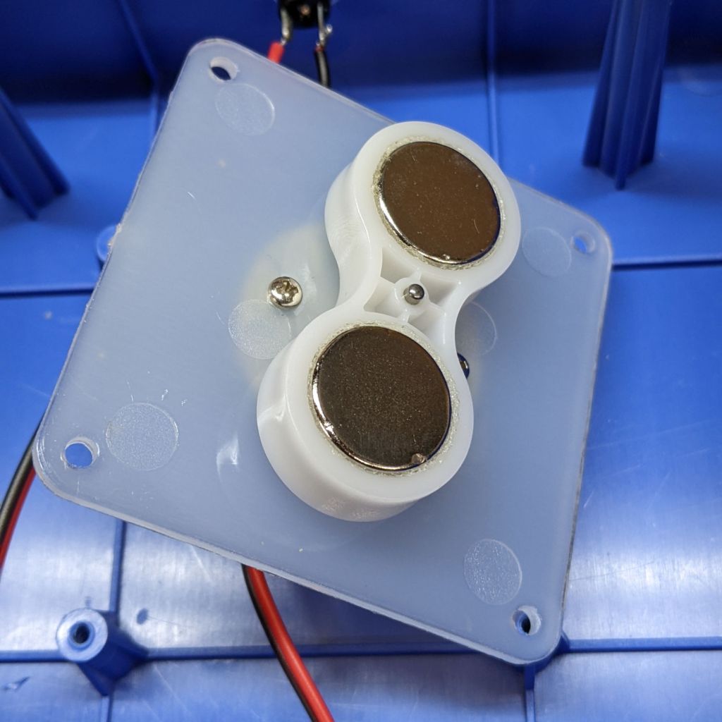
SinkOA = [31.5,12.0,15.5]; // fins forward |
|
SinkOffset = [(DriverOA.x – SinkOA.x)/2,0,2.0]; // from lower left front corner of PCB |
|
|
|
AdjPots = [14,24,34]; // screwdriver adjust offsets |
|
AdjOD = 3.0; // … access hole dia |
|
|
|
CaseOA = DriverOA + [2*WallThick,2*WallThick,2*WallThick]; |
|
echo(CaseOA=CaseOA); |
|
|
|
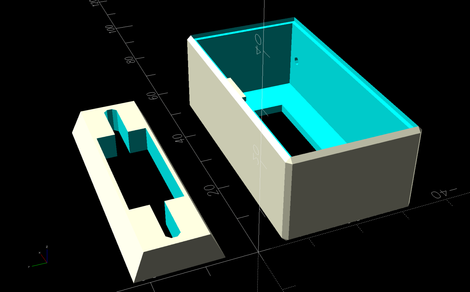
LidOA = [CaseOA.x – WallThick,CaseOA.z – WallThick,1.0]; |
|
Cables = [8.0,3.0 + WallThick/2,LidOA.z]; |
|
|
|
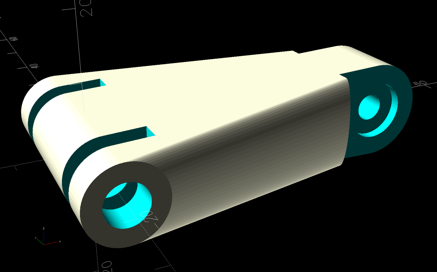
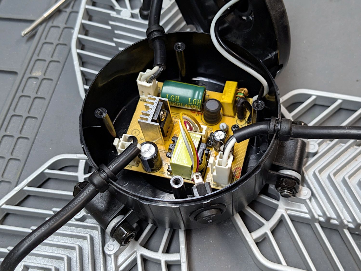
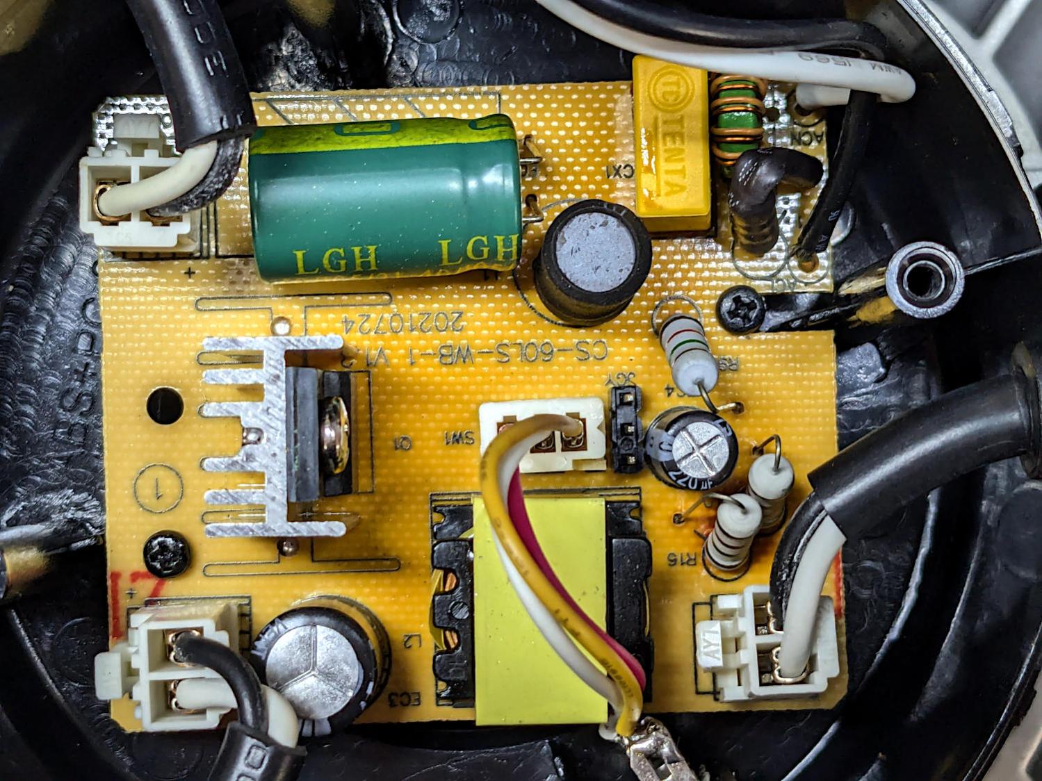
SwitchWireOC = DriverOA.x – 6.0; |
|
SwitchCapBase = [DriverOA.x + WallThick,DriverOA.y + WallThick]; |
|
SwitchCapTop = [DriverOA.x,12.0]; |
|
SwitchCavity = [25.0,10.5,5.5]; |
|
|
|
// Define things |
|
|
|
module Lid() { |
|
|
|
difference() { |
|
cuboid(LidOA,anchor=BOTTOM+FWD+LEFT); |
|
for (i = AdjPots) |
|
translate([i,LidOA.y – AdjOD/2 – WallThick/2,-Protrusion]) |
|
cyl(LidOA.z + 2*Protrusion,d=AdjOD,anchor=BOTTOM,$fn=8,spin=180/8); |
|
translate([LidOA.x/2,-Protrusion,-Protrusion]) |
|
cuboid(Cables + [0,Protrusion,2*Protrusion],rounding=1.0,edges=[BACK+LEFT,BACK+RIGHT],anchor=BOTTOM+FWD); |
|
} |
|
|
|
} |
|
|
|
module SwitchBox() { |
|
|
|
difference() { |
|
prismoid(SwitchCapBase,SwitchCapTop,SwitchCavity.z,anchor=BOTTOM); |
|
down(Protrusion) |
|
cuboid(SwitchCavity + [0,0,2*Protrusion],anchor=BOTTOM); |
|
hull() |
|
for (i=[-1,1]) |
|
right(i*SwitchWireOC/2) |
|
zcyl(CaseOA.z,d=3.0,$fn=8,spin=180/8); |
|
|
|
|
|
} |
|
|
|
} |
|
|
|
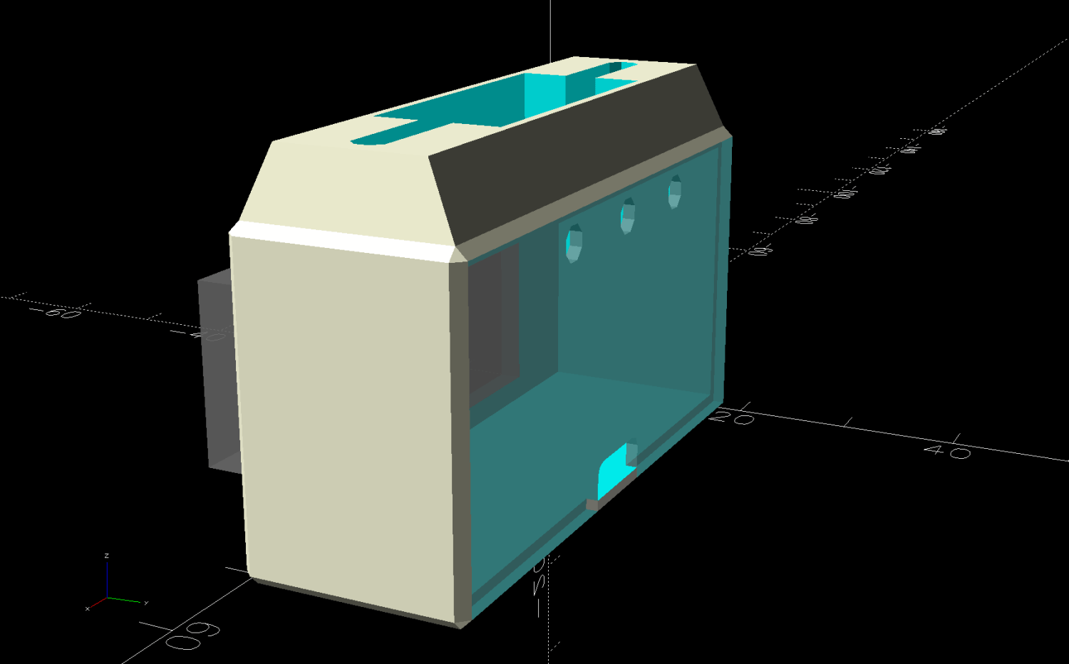
module Case() { |
|
|
|
difference() { |
|
cuboid(CaseOA,chamfer=WallThick/2,anchor=BOTTOM+FWD+LEFT); |
|
|
|
translate([WallThick,WallThick + Protrusion,WallThick]) |
|
cuboid(DriverOA + [0,WallThick + Protrusion,0],anchor=BOTTOM+FWD+LEFT); |
|
translate(SinkOffset + [WallThick,WallThick + 2*Protrusion,WallThick]) |
|
cuboid(SinkOA,anchor=BOTTOM+BACK+LEFT); |
|
|
|
for (i=[-1,1]) |
|
translate([i*SwitchWireOC/2 + CaseOA.x/2,CaseOA.y/2,CaseOA.z/2]) |
|
zcyl(CaseOA.z,d=2.0,anchor=BOTTOM,$fn=8,spin=180/8); |
|
|
|
translate([WallThick/2,(CaseOA.y + LidOA.z),WallThick/2]) |
|
xrot(90) |
|
scale([1,1,2]) |
|
Lid(); |
|
} |
|
|
|
} |
|
|
|
// Build it |
|
|
|
if (Layout == "Switch") |
|
SwitchBox(); |
|
|
|
if (Layout == "Case") |
|
Case(); |
|
|
|
if (Layout == "Lid") |
|
Lid(); |
|
|
|
if (Layout == "LidSVG") |
|
projection(cut=true) |
|
Lid(); |
|
|
|
|
|
if (Layout == "Show") { |
|
Case(); |
|
translate(SinkOffset + [WallThick,WallThick + 2*Protrusion,WallThick]) |
|
color("Gray",0.7) |
|
cuboid(SinkOA,anchor=BOTTOM+BACK+LEFT); |
|
|
|
translate([CaseOA.x/2,CaseOA.y/2,CaseOA.z]) |
|
SwitchBox(); |
|
|
|
translate([WallThick/2,CaseOA.y,WallThick/2]) |
|
xrot(90) |
|
color("Gray",0.7) |
|
Lid(); |
|
} |
|
|
|
if (Layout == "Build") { |
|
fwd(Gap) |
|
xrot(90) |
|
Case(); |
|
|
|
translate([CaseOA.x/2,(Gap + CaseOA.y/2),0]) |
|
SwitchBox(); |
|
} |