Ed Nisley's Blog: Shop notes, electronics, firmware, machinery, 3D printing, laser cuttery, and curiosities. Contents: 100% human thinking, 0% AI slop.
There’s now There was a webcam[Update: dead link] watching the recently opened Walkway Over the Hudson, put on by the Dutchess County Tourism folks.
I couldn’t quite figure out where it was, though, because there aren’t any tall buildings or towers near the Walkway. The area used to be hard industrial, with plenty of smokestacks, but those days and those structures are long gone.
On a recent trip I parked the bike at the end of the chain-link fence on the north side of the bridge, eyeballed back five-and-a-half sections of fence on the south side, and spotted what I’d been missing.
The camera is a bit more than half a mile away, atop the Interfaith Towers building at 66 Washington St, on the northwest corner at Mansion Street. The Google overhead view isn’t up to date; the Walkway’s concrete decking is done and they’re tweaking some of the electrical work even as I type.
The camera’s gooseneck mount lets that loooong telephoto lens vibrate in high winds. When the webcam image looks broken up, new weather is on its way!
The picture is a crop from a larger image, with a bit of color correction and gamma tweakage.
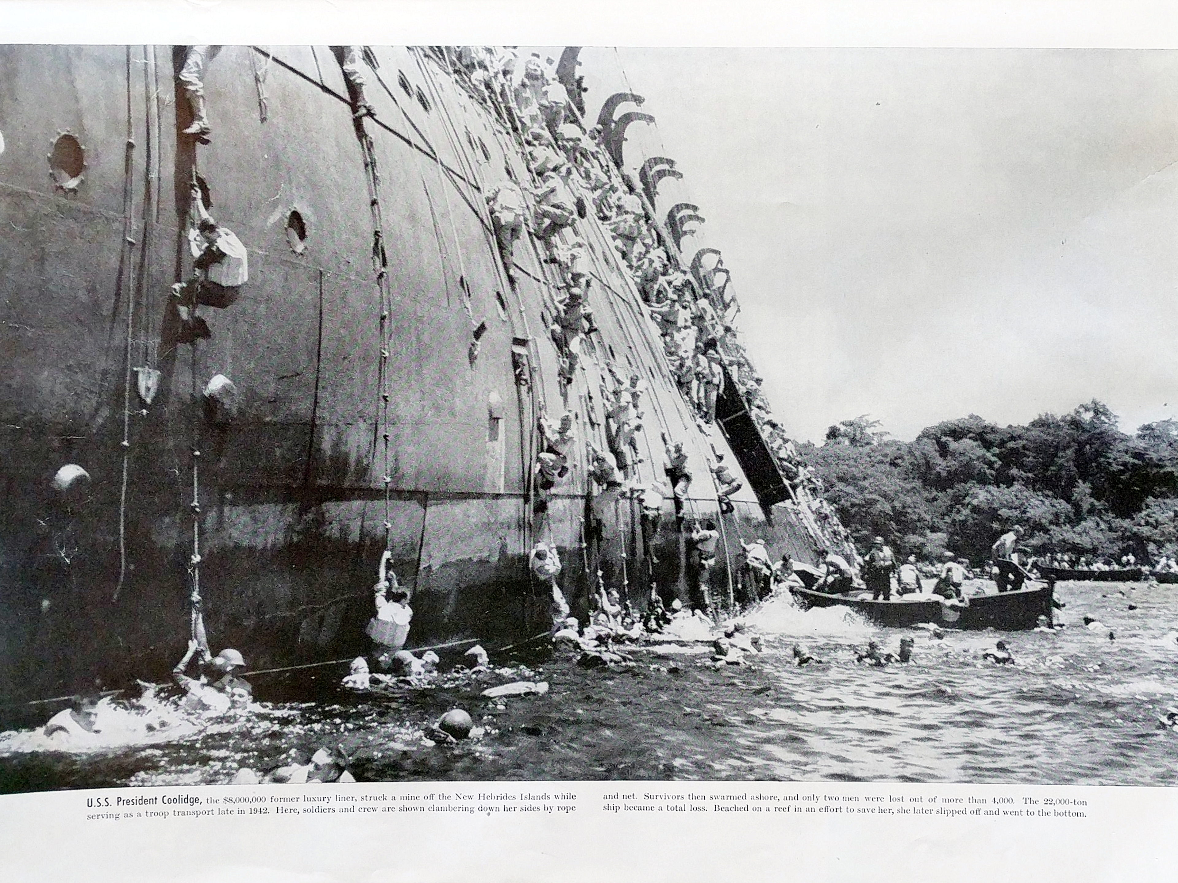
The S.S. President Coolidge, a luxury steamship converted to a troop transport, carried my father to the Solomon Islands during World War II.
All the way across the Pacific, my father and his buddies saved their chocolate and cigarette rations, because they knew supplies would be short during the actual battles.
Long story short, the captain didn’t get a vital message about the location of the American minefield at the Espiritu Santo (my father always spelled it Espirito Santo) harbor entrance and sailed right into the channel. A pair of American mines blew the bottom out of the ship, the captain ran it aground on the beach, and all but two men escaped; some actually walked from the ship to the beach. My father said one casualty was in a card game in the bilge, but that’s likely a tall tale. The other was the ship’s an Army Artillery Captain who rescued a bunch of guys in the galley infirmary. [Update: it’s been a long time since I heard him tell the story, OK?]
Anyhow, the Coolidge took all their weapons, supplies, ammunition, and the chocolate and cigarettes to the bottom of the harbor on 26 October 1942, 67 years ago today. They were right about the subsequent ration situation, too, as the Army had to resupply the entire shipload of troops before they could get down to warfare. They completely missed the battle for Guadalcanal, an event that would have probably changed my personal history.
My father passed on his hard-won lesson:
When you go to a buffet, they’ll have the desserts set out on the right side of the table. Get a dessert first and then pick up the rest of your meal. If you don’t, there might not be any when you come back.
Words to live by. I always get a dessert first and usually wind up telling that tale, hoisting a cookie to his memory.
You can find far more information about the Coolidge using the obvious search terms; start with a good summary of the events[Update: dead link. Go there or to a comprehensive narrative.] It’s evidently a spectacular wreck-diving site. Dad was in the 172nd Regiment, 43rd Infantry Division, if that helps pin it down. His Company E comrades held a reunion every year for nigh onto half a century at my parents’ house in Hummelstown PA.
[Update: An Australian movie crew making Grave of a President about the wreck asked my father if they could film the next reunion. He agreed. They then asked if the reunion, which was always held during the last weekend of September, could happen in October, because it wasn’t convenient for them to get halfway around the world on short notice. Dad said the reunion wasn’t held for their convenience. They showed up on schedule and made my father a movie star.
If you happen to have a good copy of that film, let me know.
I haven’t seen this picture anywhere else on The Web, but it’s been hanging in my parents’ house forever. It’s a photographic enlargement of a newspaper picture and in rather crappy condition after all these years, so you can’t tell that one of those guys swarming down the side (yes, like rats leaving a sinking ship) is my father…
If you’re an alpha geek, this is how you tell time…
Absolute Geek Clock
It’s a WWVB receiver wired up to a CR123A primary lithium cell. The time display is a single red LED, driven by a low-threshold FET. Yeah, you can package it up in a cute little box (which is the picture on hackaday.com), but this is the essence of the thing.
Over the course of a minute, the LED blinks out the hour, minute, year, day-of-year, Daylight Saving Time, leap year, leap second, and some other stuff in binary-coded decimal.
The key to the format is there and the bit format is straightforward:
Long = frame marker
Medium = binary 1
Short = binary 0
You just watch the LED, catch the frame marker, decode BCD data on the fly, convert from UTC to local time, and that’s all there is to it.
Sheesh, it’s only one bit a second: anybody can handle that, right?
Truth to tell, I can hang on long enough to get the minute, but I taper off pretty quickly after that.
Tech detail…
Basically, you get the receiver and CR123 cell holder from DigiKey for maybe fifteen bucks. Wire up a FET (ZVNL110A or some such) to the receiver’s inverted-polarity output, so the LED is ON during the data bit’s active time (carrier drops 10 dB). I blobbed on a 300 ohm SMD resistor, so the total current is maybe 250 µA with the LED on. If you’re going crude, you can probably wire the LED & resistor directly to the receiver’s positive-polarity output.
A primary CR123A is good for 1500 mAh and the average current is maybe 150 µA, so the clock will run for nearly a year. The LED is pretty dim, but perfect for late-night viewing.
Reception is iffy during the day here in the Hudson Valley. At night it’s just fine. Interference from LCD panels with near-60-kHz refresh is a real problem, so it doesn’t play well near PCs.
I put the clock on a shelf where I can watch it when I wake up in the middle of the night: it knocks me out again pretty quickly.
In real life, I put this together to verify my WWVB simulator… but I might just box up a spare for the shelf, too.
Found this in a church restroom, which is pretty much a benign public environment.
If you put a pushbutton control at the usual place for a light switch and give it a light-switch affordance, then you shouldn’t be surprised when people push it.
Now, if the pushbutton happens to both turn off the light and disable the automatic light function, well, that’s hardly the user’s fault, is it?
Methinks it should be an automatic light switch with a manual override tucked inside a cover that doesn’t look at all like a pushbutton. Of course, the IR lens over the sensor would then require some up-armoring, as it’d look a lot like a button.
50 cent coins will jam this machine
OK, so half-dollar coins aren’t all that common these days… but it seems to me that a vending machine shouldn’t jam on anything.
Heard two Cooper’s Hawks doing a call-and-response exchange a few mornings ago, with the nearest bird in a tall pine in the back yard. I’m surprised that a one-pound bird can perch on the very tippy-top branch of a pine without bending it over, but they seem to do this quite often.
The picture is a crop from the full frame, taken with a Sony DSC-H5 at full optical zoom with a VCL-HGD1758 1.7x Tele Conversion Lens. There’s plenty of violet fringing in evidence, which is one reason I try not to take high-contrast backlit shots like this.
Here’s a dot-for-dot crop of just the bird to show how bad the fringing really is.
Coopers Hawk Detail – Violet Fringing
It’s better than no picture at all, the way I see it…
We got a boom box so Mom could have background music; the Olde Family Tube Radio was far beyond its Best Used By date.
Prompted by recent events around here, I checked it on a recent visit and, yup, more corrosion. In all fairness, the cells suggest “Best If Installed By Jan 99”, so they’re well past their date, too.
This used to be a whole lot less of a problem when flashlights and radios (without clocks!) were the only things using “dry cells”: when the battery went dead, the thing didn’t work and you replaced the cells.
Nowadays, we expect alkaline cells to supply keep-alive trickle current for memory backup; even after the cell corrodes, it still supplies that tiny current and we never notice what’s happening inside.
I’m beginning to loathe alkaline cells just like I loathe the small internal combustion engines in yard equipment.