Ed Nisley's Blog: Shop notes, electronics, firmware, machinery, 3D printing, laser cuttery, and curiosities. Contents: 100% human thinking, 0% AI slop.
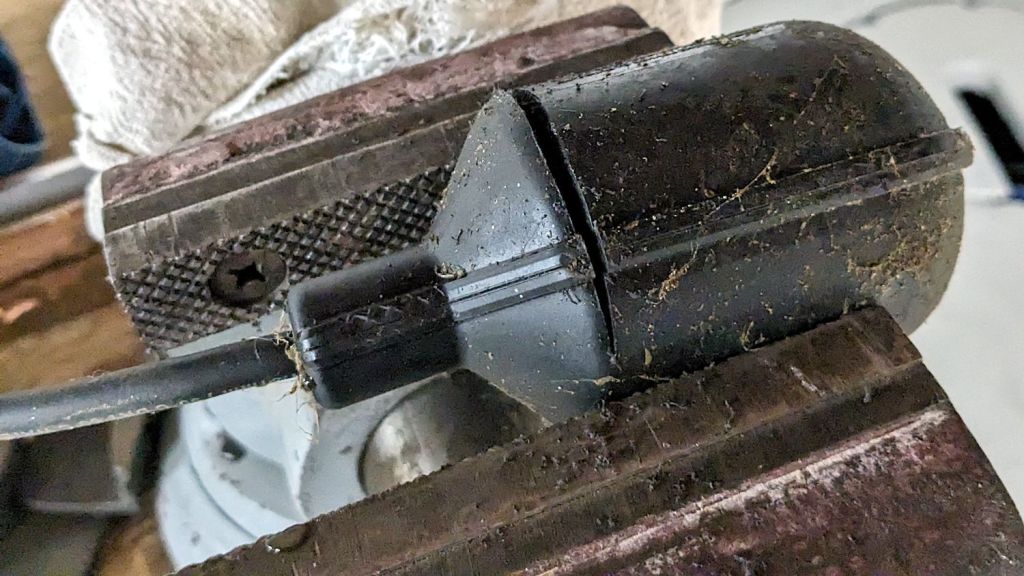
The basement curtain drain sump pits contained two ancient sump pumps badly in need of replacement, so I got to find out what made their tethered switch floats rattle like that.
Having recently stood up the Main Workbench with its big vise, I could saw without compunction:
Sump pump tether switch – sawing
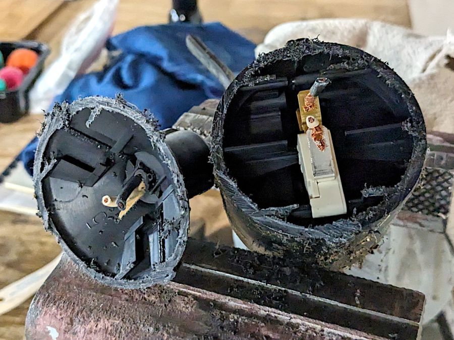
Which revealed an ordinary snap-action switch:
Sump pump tether switch – opened
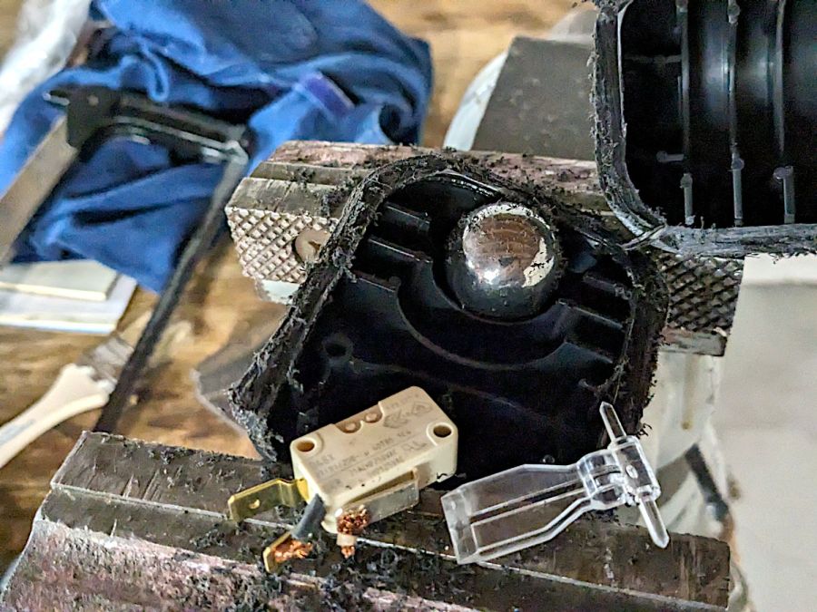
Further sawing exposed the rattler:
Sump pump tether switch – parts
Those 1 inch steel balls now nestle in the Big Box o’ Bearings and I’m sure the snap-action switches will come in handy for something.
As a temporary expedient while awaiting more outlets in the basement, I screwed several hundred watts of LED strip lighting to the floor joists so I could see where I was going:
First pass at basement lighting
The switch seemed to run warm, which I attributed to being snuggled up against one of the LED strips, eventually became intermittent, and finally failed with the lights out.
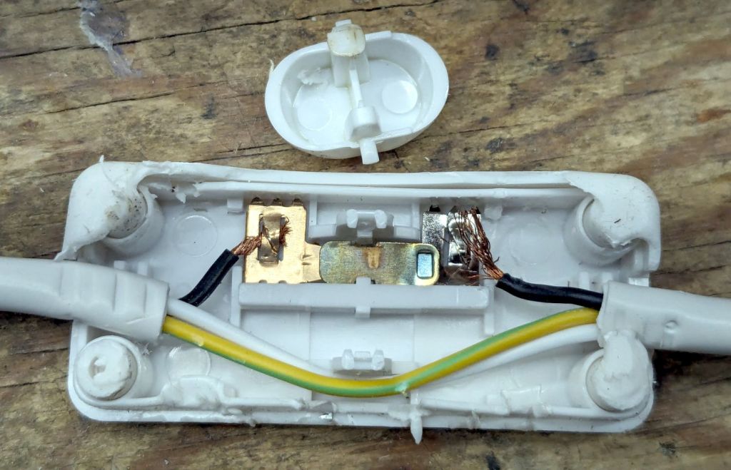
Prying apart the snapped-together case destroyed it, but that didn’t really matter when I saw the innards:
T8 LED power switch
The “intermittent” action came from the melted post on the switch actuator at the top of the photo. The “warm” came from the barely crimped black wire on the right side of the switch, which *might* have had half a dozen strands caught in the flattened crimp triangles.
I replaced it with an identical switch from the assortment that came with the lamps. That one seems to run cooler, although I doubt the crimps are really up to any reasonable quality standards.
In addition to adding basement outlets & lighting circuits, the rest of the house has some electrical wiring peculiarities; the kitchen microwave really shouldn’t share a circuit with the dining room lights.
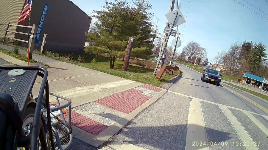
The decaying ADA bump (a.k.a. detectable warning) strips at the Dutchess Rail Trail’s Overocker Road Trailhead require cyclists to carefully pick their line. We’re on our way for groceries, so I’m towing the BOB Yak trailer and have just jounced over the edge of the concrete “ramp” while making a right-angle turn to the right:
Rollover 2024-04-09 – 0020
The four-digit frame numbers tick along at 60 FPS.
The car remained stopped at the crossing during this whole affair.
Mary is approaching along the same line with the same intent:
Rollover 2024-04-09 – 0198
A closer look shows her front wheel is parallel to the edge of the concrete ramp:
Rollover 2024-04-09 – 0198 detail
We think her wheel slipped off the edge of the concrete and, with the edge preventing her from steering left to counterbalance the sudden tilt, she knows she’s going to fall:
Rollover 2024-04-09 – 0228
Whereupon Newton took control and left no way out:
Rollover 2024-04-09 – 0250
Fortunately, this is at about zero miles per hour:
Rollover 2024-04-09 – 0276
She collected a nasty bruise on her starboard ham, plus a few scuffs here and there as the bike basically rolled over her:
Rollover 2024-04-09 – 0306
And back down again:
Rollover 2024-04-09 – 0330
Elapsed time: 100 frames = 1.7 seconds.
The drivers of vehicles in both directions rushed to assist Mary, but, apart from a few bruises and scrapes, she was in good shape.
The fairing incurred fatal cracks, but held together as we completed the mission. No surprise: after nearly a quarter-century of sunlight exposure, polycarbonate loses a lot of its durability.
Now, to be honest, we both ignored the Dismount before crossing road sign at the intersection. Over the years, I have seen a few cyclists stop and dismount before walking through the trail’s at-grade road crossings, but they are most certainly the rare exception; we all stop while waiting for traffic to recognize our presence, then ride through.
Rail trail maintenance has always been a low priority and the County’s “Vision Statements” over the decades have been largely irrelevant to what actually happens out on the pavement. ADA strips at trail crossings have been decaying for years and I expect that to continue for many more.
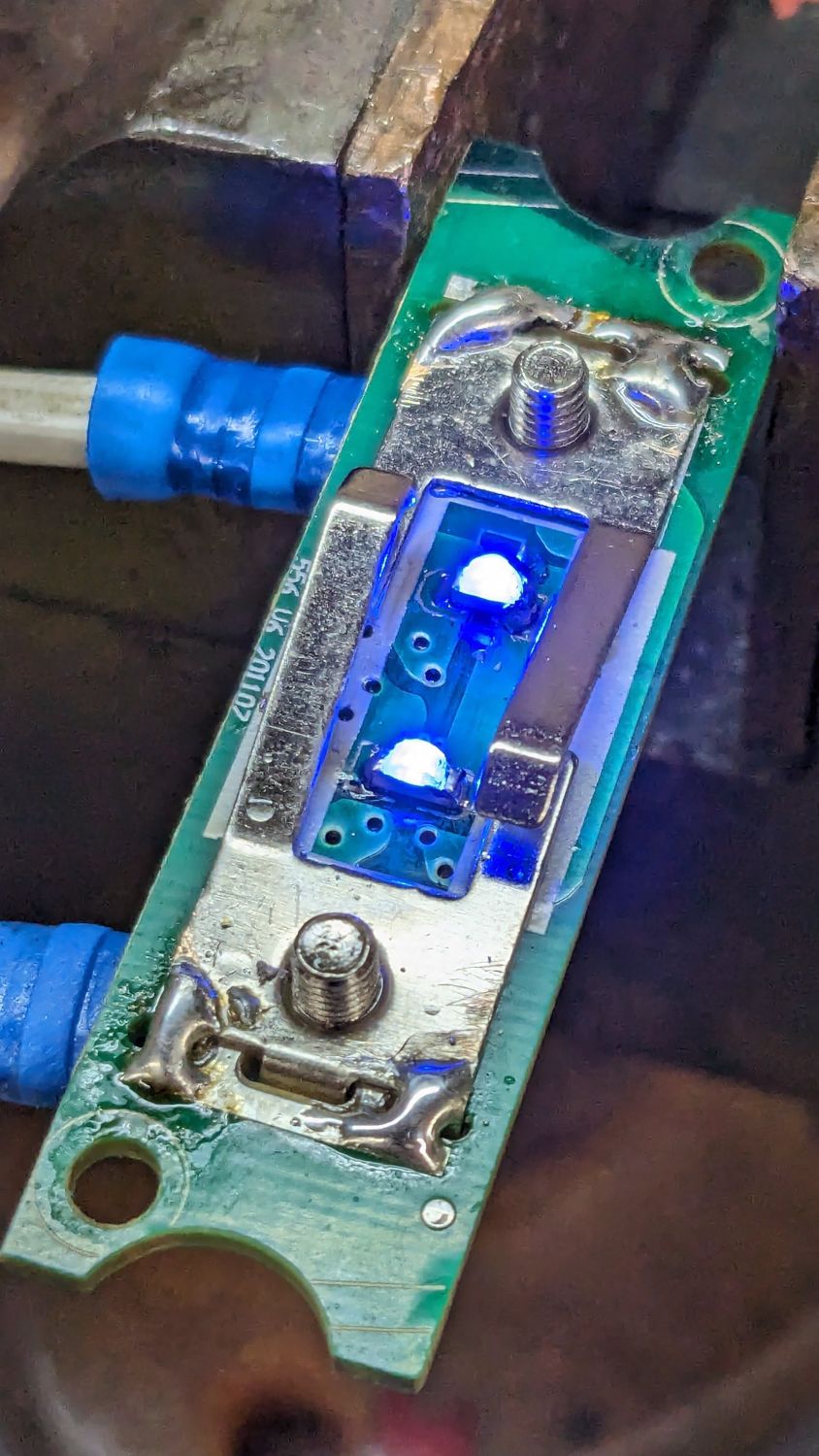
Having had several folks ding our front doorbell in recent weeks, I thought it would be nice if the switch had a light inside and was mildly surprised it didn’t. Taking it apart revealed an even bigger surprise:
Doorbell – circuitry
Much electronic! Many solder!
Obviously, that’s a bridge rectifier (MB6S for the curious) in the middle, with a pair of paralleled 1 kΩ SMD resistors on either side ballasting two white LEDs in series on the other side. As far as I could tell, both LEDs had stopped being diodes, most likely after one failed short and took the other down with it.
Having recently unpacked the small parts cabinet containing SMD LEDs, I could do this:
Doorbell – blue LEDs
While I had the iron hot, I resoldered the fractured blobs attaching the spring contacts to their solder pads. I think the 201107 along the left edge is the PCB date code, so the switch has been in place for maybe a decade.
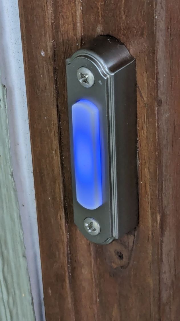
You gotta admit blue is distinctive:
Doorbell – installed
While taking it off, I discovered it’s the second doorbell button in that spot; you can’t see the bottom screw hole and wood scar when you’re standing at the door. Unless, I suppose, you’re three feet tall, but most folks of that stature aren’t curious about doorbells.
Update: An alert reader provided more information:
I recently bought a doorbell button, Heath Zenith SL-315-1-90. […] My board is different but has the same circuit as yours. In case it’s helpful, I believe your button might be Heath Zenith SL-257-02.
That’s a perfect example of a “brand name” completely detached from its entire history and put to work doing something entirely different. AFAICT, I honored the Heath name by resoldering the poor thing.
Alas, the doorbell switch on the back door turned out to be a dead loss. Perhaps when they replaced the door, the wire got sliced just above the sill plate, leaving a stub in the basement and no way to fish a new wire to the switch. Anybody arriving via the trail from the Vassar College property out back must bang on the door to get our attention.
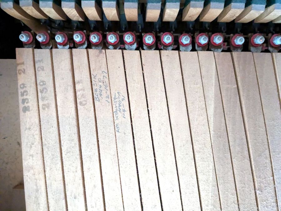
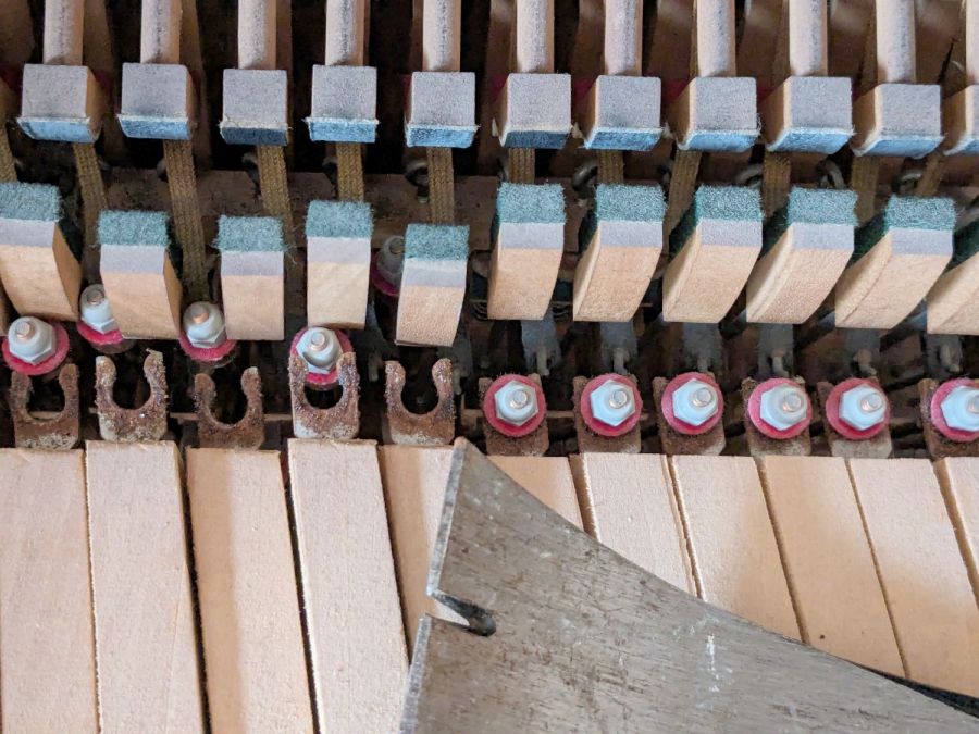
It’s apparently customary for piano tuners to annotate their work on the keys, starting after the serial numbers on the bass notes at the left end:
Piano tuner notes
After admiring that, you can pop the hammer links off with a prybar:
Detaching piano keys
All 88 keys stack neatly into a Home Depot Extra Small moving box, filling it about 2/3 full, starting with the bass keys on the bottom:
Boxed piano keys
I harvested the lovely wood panels, then the scrapper hauled the carcass to the transfer station. Perhaps it raised the secret chord when it hit the bottom …
Lest you wonder why we didn’t try to contact X, who would surely be interested in a free piano: we did. Believe me, we tried, for many values of X, only to find nobody wants a piano in this day and age.
Mary’s new Sewing Room (f.k.a. The Living Room) has a set of cellular blinds over the windows:
Sewing Room – Cellular shades
They have internal springs instead of pull cords: you just grab the tabs on the lower bar to raise / lower the shade. This worked with one hand for the narrower shades on the sides, but the center shade seemed unusually difficult to move, even with one person on each end.
Then, one morning, the center shade jammed in place about halfway up and resisted all persuasion to move in either direction. So I evacuated all the plants, dismounted the shade, laid it out on the quilting table, and found a sticker showing they were manufactured in 2018:
Cellular shade – data plate
They were surely installed shortly thereafter, so they’re the better part of six years old. Although parts are available for some shades, casual searching suggested replacing all three blinds (because color matching) would require more attention than I wanted to apply in the midst of our ongoing real estate transactions.
Gingerly removing the spring released the tension on the mechanism and a vast array of cords, so I could lay things out and see how the shade was supposed to work:
Cellular shade – cord layout
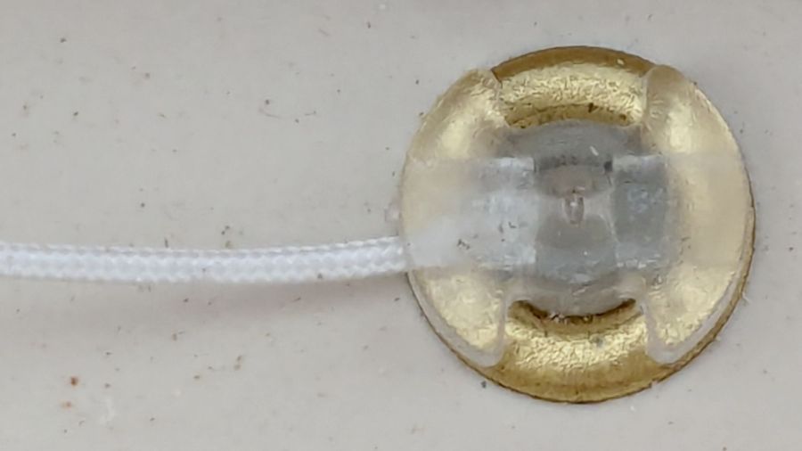
Four cords support the lower bar, pass through the entire height of the shade, and emerge through plastic guides into the upper bar:
Cellular shade – grommet
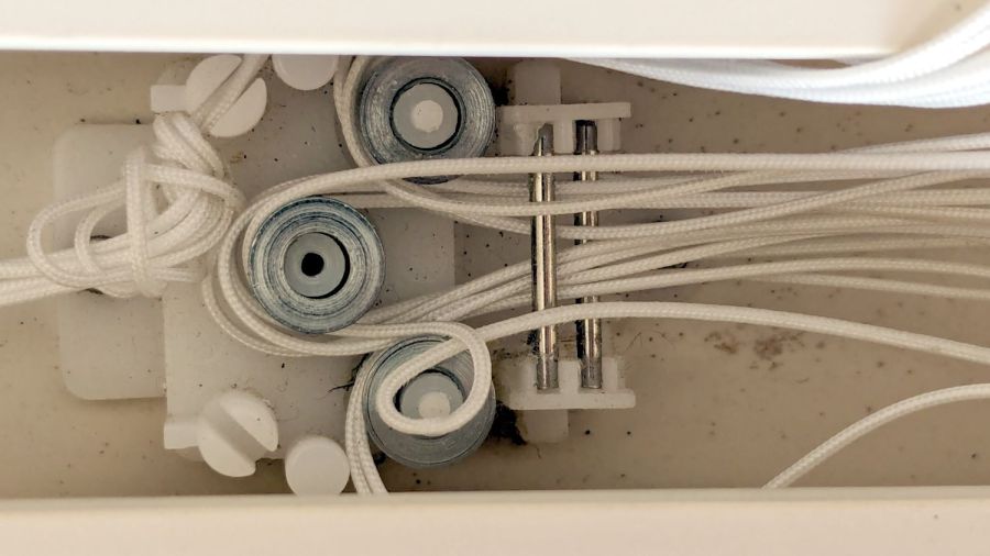
All four cords pass around pulleys in the fixed block on the left, to more pulleys in the movable block on the right, then back to the fixed block where they are tied off:
Cellular shade – cord snag
The possibility of successfully re-stringing those cords from a cold start is exactly zero, so I knew I must not fumble anything.
The hook on the right side of the movable block connects to the spring counterbalancing the weight of the shade:
Cellular shade – block missing cord
After considerable pondering, I noticed the upper pulley has four cords on its outer side and the lower pulley has only three. Reasoning by symmetry, I concluded that can’t possibly be right.
Gentle poking at the fixed block showed where the missing cord went:
Cellular shade – errant cord
Apparently the loop slipped off the lower pulley in the movable block, distributed several feet of loose cord somewhere inside the shade, and eventually bound tight around the lower pulley in the fixed block.
Removing the cover from the fixed block confirmed the diagnosis:
Cellular shade – fixed block disassembly
Removing the cover from the movable block shows the cord layout, with the lower pulley still missing one loop:
Cellular shade – block cord layout
Gingerly pulling the loose cord from deep inside the shade, I managed to extend the errant loop back around the pulley in the movable block, then, following the “First, do no harm” part of the Hippocratic Oath, I immobilized all the cords in their current positions relative to all the pulleys / pins / blocks:
Cellular shade – block cords sorted
Which revealed how the cord got loose in the first place:
Cellular shade – block side view
Apparently half a dozen years is enough to warp a thin plastic plate. Who would have expected that?
With the cords sorted out, I eased them off the pulleys, freed the block, and discovered the situation was worse than I thought:
Cellular shade – block warp
Now that I knew what to look for, it was obvious the tiny pin molded into the boss supporting the lower pulley had broken, allowing the cord to slide between the pulley and the top plate. You can see the dark hole vacated by the pin in the first picture of the upper block.
Knowing what I had to do next, I snipped the pin off the other boss with flush-cutting pliers.
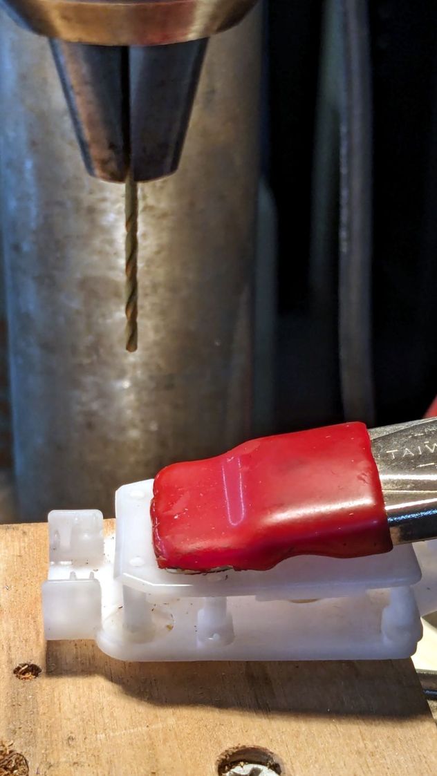
Line up the drill press using the top plate to center the drill in the boss, drill a hole suitable for a small screw, and repeat for the other pulley:
Cellular shade – block drilling
At that point, the New Basement Shop™ consisted of empty shelves and full moving boxes, but the drill press and tool chests were accessible. The basement has four outlets, one in each far-distant corner, but I have extension cords and know how to use them; I intend to spray-paint the walls with outlets in the near future.
With the holes drilled, I restored the pulleys / pins / cords to their proper locations:
Cellular shade – cord sorting
Almost proper, as it turned out I put the errant loop on backwards, so I had to go through one completely assembly / test / disassembly cycle.
The two new screws in the pulleys, in addition to the two old screws along the midline, hold the top plate flat against the bottom plate, with the remaining pins seated securely in their holes.
Reassemble in reverse order, tension the spring, snap it on the movable block, and reinstall in the window. I don’t have any pix of the completed assembly, but the shade now works as it should: we can raise and lower it from either end with just a bit of effort.