The humidifier that Came With The House™ had a lid with two broken plastic hinges that I figured I could never replace, but while cleaning out the fuzz for the upcoming season I found one missing piece stuck inside the lid. Given a hint, I glued it back in place:

There’s a strip of duct tape around the outside holding the fragment in place while the adhesive cured.
A manual curve fit to the image in Inkscape produced the red outline, which gets saved as a plain SVG and fed into OpenSCAD to create a solid model:

The cylinder doesn’t exactly fit the end of the hinge, but it’s close enough. The straightforward OpenSCAD code making that happen:
// Humidfier Hinge Replacement
// Ed Nisley KE4ZNU
// 2024-10-20

HingeThick = 10.0;
PinLength = 10.0;

ScrewOD = 2.0;

NumSides = 2*3*4;
Protrusion = 0.1;

difference() {
    union() {
        translate([0,0,HingeThick])
            cylinder(d=6.0,h=PinLength,$fn=NumSides);

        linear_extrude(height=10.0,convexity=5)
            translate([-3.1,-8.0])
                import("Humidifier Hinge - ouline.svg");
    }

    cylinder(d=ScrewOD,h=4*(HingeThick + PinLength),center=true,$fn=8);
}
The pin has a hole for a M2 screw, but contemplation of the broken pieces suggested the pin wasn’t the weakest link, which later experience confirmed.
Figuring I’d need only one hinge, I made a spare for fitting:

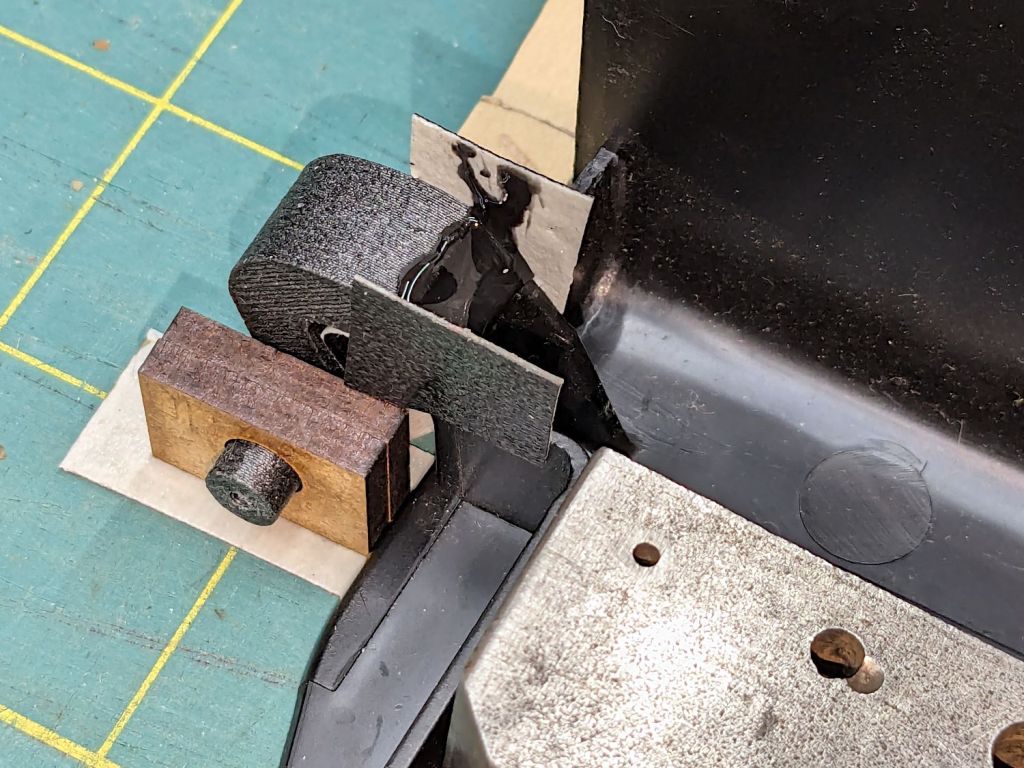
The unmodified part fit just about perfectly, whereupon a completely ad-hoc fixture involving a pair of laser-cut MDF slabs, a craft stick epoxy mixer, and more duct tape held it in place while the adhesive cured:
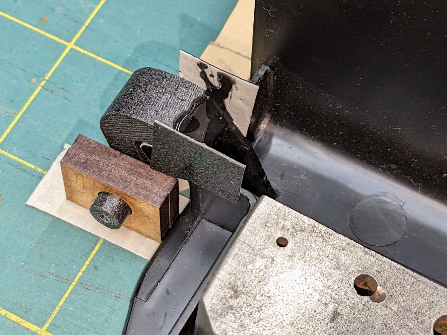
The hinge pin turned out to be half a millimeter too long, which is easily fixed, and it worked fine:

That’s more duct tape wrapped around the perimeter to hold the pieces in place, should it break again.
Which, I regret to report, occurred on the way up the stairs from the Basement Shop™ when the lid slipped from my grasp, fell away from the rest of the humidifer’s top panel, and jammed open:
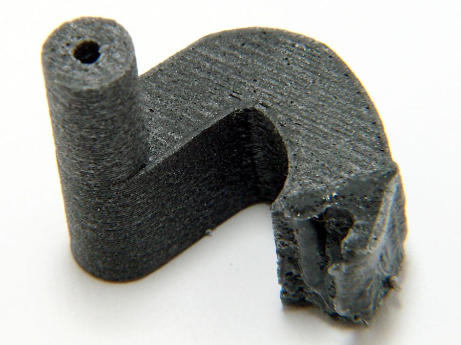
The PETG-CF part held together, the adhesive remained bonded to both pieces, but the original plastic fractured just below the joint. A closer look from the other side shows the break:
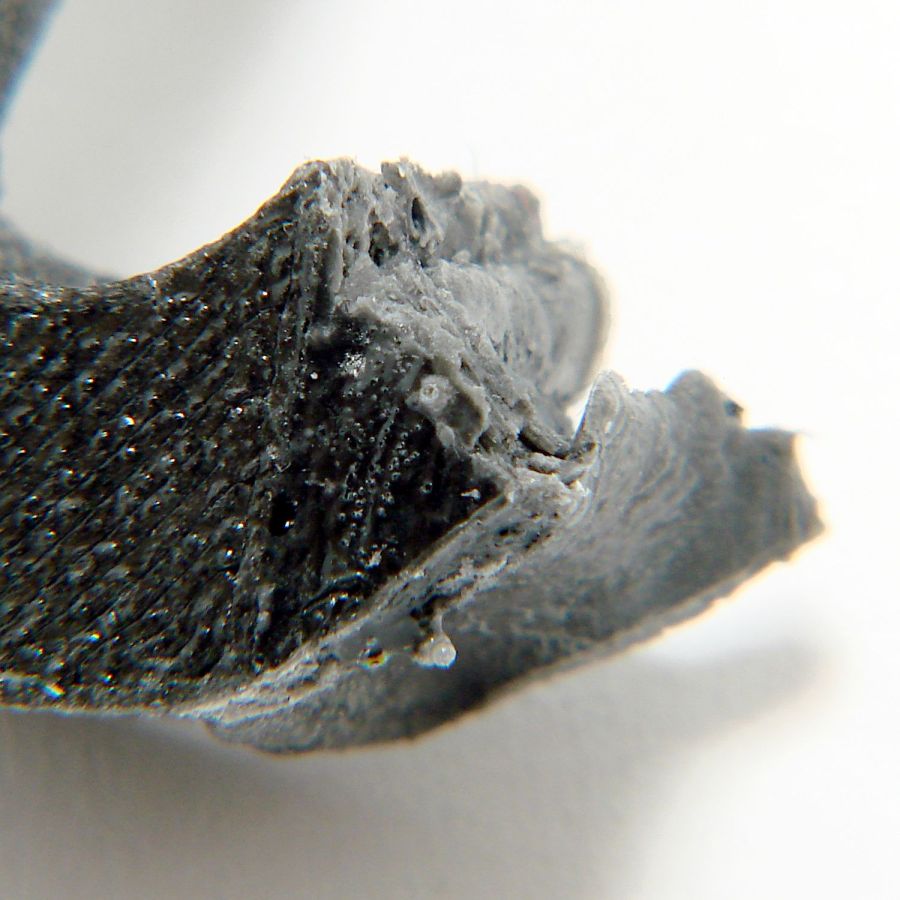
The other hinge broke about where it did before.
So the humidifier remains in service with the lid in status quo ante and a small bag inside holding the fragments for the next return to the shop.
Drat!


