The Smell of Molten Projects in the Morning

Ed Nisley's Blog: Shop notes, electronics, firmware, machinery, 3D printing, laser cuttery, and curiosities. Contents: 100% human thinking, 0% AI slop.

Author: Ed

  • Hall Effect Current Sensor: Winding and Armoring the Toroid

    Winding a slit ferrite toroid poses no challenge, so putting 25 turns of 26 AWG wire on it didn’t take long at all:

    F50-61 toroid - 25 turns 26 AWG
    F50-61 toroid – 25 turns 26 AWG

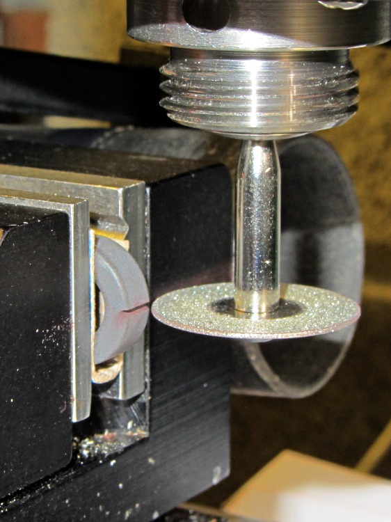
    However, a ferrite toroid doesn’t take kindly to being dropped and I figured that a slit toroid would crack under a stern look, so I decided to wrap some armor around it. A small squeeze bottle offered a cap just slightly larger than the winding, so I used that slitting saw to cut off a suitable ring.  The first step was to grab it in the 3 jaw chuck and align its axis parallel to the spindle:

    Aligning bottle cap in 3-jaw chuck
    Aligning bottle cap in 3-jaw chuck

    I wanted to cut off a slightly taller ring, but the clamping screw on the saw arbor just barely cleared the chuck for a 5 mm ring. I jogged around the chuck jaws to cut two slits in the cap that eventually joined near the back:

    Slicing ring from bottle cap
    Slicing ring from bottle cap

    That was about 1000 rpm, no coolant, and slow feed, but also a totally non-critical cut in plastic.

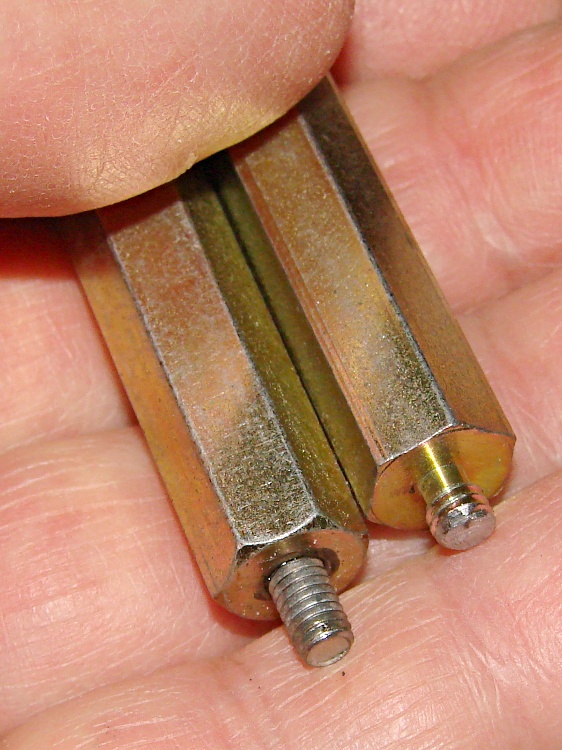
    I put a snippet of foam rubber in the slot, put the ring on a Kapton-covered build platform from the Thing-O-Matic, filled it with hot-melt glue, gooshed the toroid in place, and waited for cooling. Trimming and cleaning out the slit produced a hideously ugly, but (I hope) much more durable assembly:

    Slit ferrite toroid - with armor
    Slit ferrite toroid – with armor

    I’m reasonably sure I didn’t crack the ferrite while cleaning out the slit; that hot-melt glue is tenaciously gummy stuff!

    Now, to find out whether it actually works…

  • Slitting a Ferrite Toroid

    The object of the game: cut a slit into a ferrite toroid that will accommodate a Hall effect sensor. Those doodles showed that an FT50 (half-inch OD) toroid would be about right for the cheap AH49/EH49 Hall effect sensors on hand and those doodles shows that the permeability of the ferrite mix doesn’t make much difference. Not being quite sure how this would work out, I figured I’d start with the simplest possible setup and complexicate things until it worked…

    A fold of cereal box cardboard cushioned the brittle ferrite in the Sherline’s clamp and the vacuum hose in the background collects airborne grit. I touched off X=Y=Z=0 with the wheel at the center of the toroid’s equator:

    Slitting ferrite toroid - first pass
    Slitting ferrite toroid – first pass

    The first pass went swimmingly, with the diamond wheel far more concentric than I expected, using manual jogging along a 0.5 mm deep cut. The wheel is slightly over 0.5 mm thick, measured on the grit, and showed no sign of strain on a 1 mm deep cut at 100 mm/min, so I used manual CNC to run the wheel back and forth along the cut.

    After clearing the slot, I moved the wheel upward to + 0.5 mm, repeated the passes with a 1.5 mm depth of cut, then did the same at -0.5 mm. The end result was a nice slot with parallel sides:

    Slitting ferrite toroid - complete
    Slitting ferrite toroid – complete

    The actual gap measured 1.72 mm, not the 1.5 I wanted, which means the flux density will be lower than the previous calculations predict. Assuming the Z axis backlash compensation works as it should, then the kerf is 0.72 mm. Of course, that also assumes the arbor runs true and the wheel cuts symmetrically, neither of which I’d put (or, heck, have put) a lot of money behind. On the other paw, the sensors are 1.5 mm thick (just under the datasheet’s 1.6 mm spec), so +0.1 mm clearance on each side works a whole lot better for me than, say, -0.1 mm.

    All in all, there was no excitement, no muss, no fuss, no chipping, no breakage:

    FT50 ferrite toroid with slit
    FT50 ferrite toroid with slit

    Talk about beginner’s luck!

  • Hall Effect Current Sensor: More Toroid Numbers

    After rummaging in the collection, it turns out those calculations for the FT50-43 toroid aren’t relevant: I only have a few of them. It turns out that the actual material doesn’t affect the result nearly as much as you’d think, because the air gap for the Hall sensor controls the net permeability, so I’ll start sawing toroids that I have in abundance…

    The J ferrite mix has much higher permeability, at the cost of a lower Curie point. An FT50A toroid is slightly thinner and taller than an FT50, but I have good assortment of FT50A-J toroids:

    • 0.50 inch OD = 1.27 cm
    • 0.312 inch ID = 0.793 cm
    • 0.250 inch height = 0.635 cm
    • 0.152 cm2 area
    • 0.558 cm3 volume
    • 3.68 cm mean path length
    • μ = 5000
    • 4300 saturation flux (G) at 10 Oe
    • AL = 2970 nH/turn2

    For 1000 G flux in a 0.15 mm air gap:

    1000 = (0.4 π · 5000 · NI) / (3.68 + 5000 · 0.15) = 8.34 · NI

    So NI = 1000/8.34 = 120, essentially the same as NI = 122 for the FT50-43. Given that μ increased by nearly a factor of 6, that shows permeability doesn’t matter very much at all.

    There’s a bag of F50-61 toroids that I assume are actually FT50-61:

    • 0.50 inch OD = 1.27 cm
    • 0.281 inch ID = 0.714 cm
    • 0.188 inch height = 0.478 cm
    • 0.133 cm2 area
    • 3.02 cm mean path length
    • 0.401 cm3 volume
    • μ = 125
    • 2350 saturation flux (G) at 10 Oe
    • AL = 68.0 nH/turn2

    Running those numbers for the same flux and gap:

    1000 = (0.4 π · 125 · NI) / (3.02 + 125 · 0.15) = 7.21 · NI

    Which gives NI = 1000/7.21 = 139. That’s larger, but still in the same inconvenient range.

    I’ll start sawing a FT50-61 toroid…

  • Muting the Optiplex 760 Internal Speaker

    The Dell Optiplex 760 that I’m using as a rendering box has an internal “business audio” speaker that is not disabled by plugging an external speaker / earphone into either the front or rear audio output jack. The tiny volume control applet in the Xubuntu 12.04 notifications panel doesn’t provide any control over the sound card; it’s definitely not a mixer and its Sound Settings button calls up the Pulseaudio configuration which is oddly unhelpful.

    So.

    Install xfce4-mixer, add it to the panel, fire it up, select the HDA Intel “sound card”, enable all the controls, slide rightward until Mono appears, click the speaker button under the slider to mute it, and you’re done.

    Memo to Self: there ought to be a BIOS setting for that.

  • Windows 7 Home Premium Remote Desktop: The Missing Link

    The tiny Lenovo Q150 has become the dedicated Windows box for running TurboTax this season. In earlier years, I used the Token Windows Laptop through a remote desktop session that appears on a Xubuntu desktop, but the Q150 runs rings around the old laptop.

    This time, no matter what I tried, I couldn’t connect to the Windows 7 desktop on the Q150 from my Xubuntu desktop. The usual search results suggested Windows configuration settings that didn’t quite match what the Q150 provided; a bit more searching revealed that Windows 7 Home flavors of the OS (this one is Home Premium) lack the Remote Desktop Protocol server required to export the desktop. The Q150 could act as a client that controlled another machine’s desktop server, but not the other way around.

    The suggested solutions required applying patches, in the form of EXE files downloaded from sketchy websites, or dropping in replacement DLLs obtained from similar sites. All that seems like Bad Practice, particularly for a Windows box used to prepare our taxes, and I was unwilling to proceed along those lines.

    Instead, I fetched UltraVNC, installed it on the Q150, and it works perfectly. Remmina occasionally requires a resize-window-to-match-server at startup and then it’s all good.

    From what I hear, Windows 7 doesn’t display the classic Blue Screen of Death nearly so often as before, although I did manage to lock it up during the course of this adventure. That’s OK, I can still use my favorite Windows wallpaper image:

    Windows 7 Home - UltraVNC via Remmina
    Windows 7 Home – UltraVNC via Remmina

  • Lenovo Q150 VESA Mount Hackage

    A permutation of our *cough* computing resources put the diminutive Lenovo Ideacentre Q150 flat on a desktop, where it was at risk of falling off due to the weight of the cables. It came with a VESA monitor mount bracket designed under the assumption that monitor manufacturers would provide an unused VESA socket and a completely separate desk stand mount, which turned out to be incorrect for all of the monitors in my collection. The IBM (pre Lenovo) monitor it was now driving, however, had exposed screws on its VESA mount, so I adapted a quartet of hulking standoffs to hold the Q150 far enough away to clear the desk stand.

    One end had 4-40 tapped holes that I drilled out to clear the VESA mount’s M4x0.7 screws; I sawed the heads off four M4 screws and epoxied them in place. The other end had 8-32 studs that I cut down to fit inside the Q150’s dished mounting bracket:

    VESA Mount - standoffs
    VESA Mount – standoffs

    Working around the mount, one standoff at a time, avoided having to lay the monitor flat on the desk:

    VESA Mount - standoffs on monitor
    VESA Mount – standoffs on monitor

    A bit of jiggling put the bracket on the standoffs, held in place by the 8-32 nuts:

    Lenovo Q150 VESA Mount on monitor
    Lenovo Q150 VESA Mount on monitor

    And then the Q150 snapped into place:

    Lenovo Q150 - on VESA Mount
    Lenovo Q150 – on VESA Mount

    It’s captured by a thumbscrew in the bottom left corner (visible in the previous photo), so it can’t fall out.

    Took longer to take the pix and write this up than to finish the project… probably because there wasn’t a trace of CNC in sight.

  • Stepper Motor Driver Spec Comparison

    Being in the market for some more-or-less industrial stepper driver bricks, here’s a summary of what’s currently available on eBay from the usual vendors, copied-and-pasted directly from the descriptions with some fluff removed:

    M542 Stepper Driver Board Controller

    • Supply voltage from 20V DC to 50V DC
    • Output current from 1.0A to 4.5A
    • Self-adjustment technology, full to half current self-adjustment when motors from work to standstill via switching off SW4
    • Pure-sinusoidal current control technology
    • Pulse input frequency up to 300 KHz
    • TTL compatible and optically isolated input
    • Automatic half-current reduction as long as switching off SW4 when motors stop
    • 16 selectable resolutions in decimal and binary, up to 51,200 steps/rev
    • Suitable for 2-phase and 4-phase motors
    • Support PUL/DIR and CW/CCW modes
    • Short-voltage, over-voltage, over-current and short-circuit protection, protect the PC, motors, driver etc from being damaged

    M542H Stepper Driver Board Controller

    • Supply voltage from 20V DC to 100V DC
    • Output current from 1.0A to 4.5A
    • Self-adjustment technology, full to half current self-adjustment when motors from work to standstill via switching off SW4
    • Pure-sinusoidal current control technology
    • Pulse input frequency up to 300 KHz
    • TTL compatible and optically isolated input
    • Automatic half-current reduction as long as switching off SW4 when motors stop
    • 16 selectable resolutions in decimal and binary, up to 51,200 steps/rev
    • Suitable for 2-phase and 4-phase motors
    • Support PUL/DIR and CW/CCW modes
    • Short-voltage, over-voltage, over-current and short-circuit protection, protect the PC, motors, driver etc from being damaged

    2M542 Stepper Driver Board Controller

    • Suitable for 2-phase hybrid stepper motors (Outer diameter: 57,86mm)
    • H bridge bipolar constant phase flow subdivision driver
    • Speed self-adjustment technology
    • Easy current subdivision setting
    • 2–64 resolutions,16 operation modes
    • ENA mode
    • 8 dial switch for different functions
    • Undervoltage, Shortvoltage, overvoltage, overcurrent protections
    • Supply Voltage: 24~50V DC (Typical 36 V)
    • Output Current (peak): Min 1.0 A, max 4.2A
    • Logic Input Current: Min 7, typical 10, max 16 mA
    • Pulse Frequency: Max 200 KHz
    • Pulse Low Level of Time: 2.5 US
    • Cooling: Natural /mandatory
    • Working Surrounding: Avoid dust, oil mist and corrosive gas
    • Storage Temp: -10—80 deg
    • Working Temp: Max 65 deg
    • Surrounding Humidity: <80%RH without condensing and frost
    • Vibration: 5.9m/s²
    • Model: 2M542
    • Size: Approx. 4 5/8 x 3 x 1 5/16 inch (L x W x H)

    MA860H Stepper Driver Board Controller

    • Supply voltage from “18V AC to 80V AC” or “24V DC to 110V DC”
    • Output current from 2.6A to 7.2A
    • Self-adjustment technology, full to half current self-adjustment when motors from work to standstill via switching off SW4
    • Pure-sinusoidal current control technology
    • Pulse input frequency up to 300 KHz
    • TTL compatible and optically isolated input
    • Automatic half-current reduction as long as switching off SW4 when motors stop
    • 16 selectable resolutions in decimal and binary, up to 51,200 steps/rev
    • Suitable for 2-phase and 4-phase motors
    • Support PUL/DIR and CW/CCW modes
    • Short-voltage, over-voltage, over-current and short-circuit protection, protect the PC, motors, driver etc from being damaged
    • External Fan Design to avoid overheat

    2M420 Stepper Motor Driver controller

    • H-Bridge, 2 Phase Bi-polar Micro-stepping Drive
    • Suitable for 2-phase, 4, 6 and 8 leads step motors, with Nema size 17
    • Supply voltage from 20V DC to 40 DC
    • Output current selectable from 0.9 ~ 3.0A peak
    • Current reduction by 50% automatically, when motor standstill mode is enabled
    • Pulse Input frequency up to 200 kHz
    • Optically isolated differential TTL inputs for Pulse, Direction and Enable signal inputs
    • Selectable resolutions up to 25000 steps
    • Over Voltage, Coil to Coil and Coil to Ground short circuit protection.

    2M982 CNC Stepper Motor Driver

    • Supply voltage: 24~80V DC
    • Suitable for 2-phase stepper motors
    • Output current: Min 1.3A Max 7.8A
    • Speed self-adjustment technology
    • Pure-sinusoidal current control technology
    • Pulse input frequency: Max 200 KHz
    • Optically isolated input and TTL compatible
    • Automatic idle-current reduction
    • 15 selectable resolutions, MAX 12,800 steps/rev
    • PLS, DIR (CW/CCW), ENA mode
    • Undervoltage, Shortvoltage, overvoltage, overcurrent protections

    Leadshine DM1182

    • 2 Phase Digital Stepper Drive
    • Direct 115VAC input
    • Current 0.5 – 8.2A
    • Max 200 kHz

    In round numbers, the M542 seems to be the basic driver for NEMA 17 / 23 /34 steppers. Remember that current isn’t proportional to frame size.

    The M542H has a higher voltage limit that may be more useful with larger / multiple-stack motors; higher voltage = higher di/dt for a given inductance = same di/dt for higher inductance.

    The 2M542 seems to be slightly different from both of its siblings: higher minimum voltage, slightly lower maximum current, slower step frequency. Many of the listings apply both M542 and 2M542 to the same hardware in the same listing, so it’s not clear what you’d get in the box. Ask first, trust-but-verify?

    The MA860H seems appropriate for NEMA 34 / 42 and up , due to the much higher minimum current.

    The 2M420 seems to be intended for NEMA 17 /23 class steppers. It’s not available from nearly as many suppliers.

    The 2M982 looks like another NEMA 34 /42 and up driver.

    The DM1182 seems strictly from industrial, but if you don’t know what you need, it’s a do-it-all killer.

    As with all eBay listings, the picture need not match the description and neither may match what actually arrives in the box from halfway around the planet.