Ed Nisley's Blog: Shop notes, electronics, firmware, machinery, 3D printing, laser cuttery, and curiosities. Contents: 100% human thinking, 0% AI slop.
The first Wouxun (evidently pronounced “ocean”) KG-UV3D HT spent a month or two in my bike, lashed to a kludged version of the APRS+voice interface box and powered by its own lithium-ion pack. After I got the circuit worked out and built a duplicate, I picked up a second HT for Mary’s bike; as a result, that battery pack never got much use.
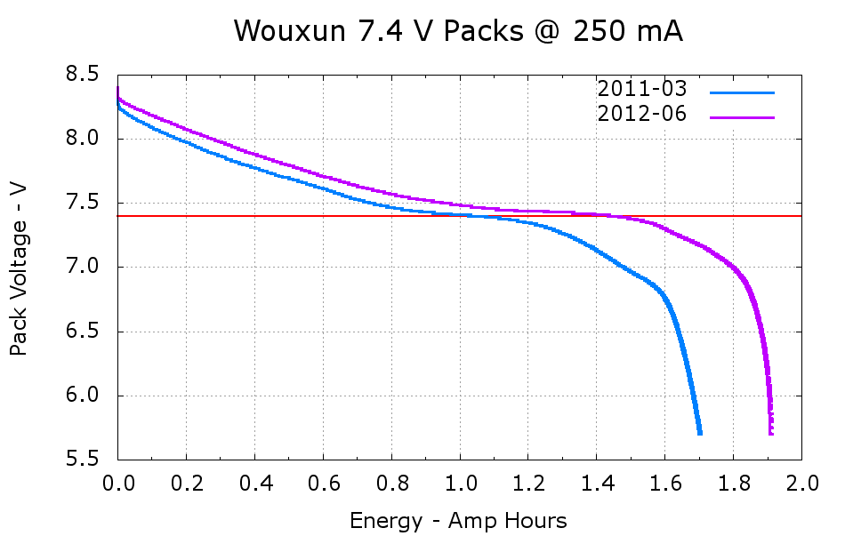
A pair of discharge tests shows the difference:
Wouxun 7.4 V Packs
The 2011-03 battery has almost exactly the rated 1.7 A·h capacity, at least if you’re willing to run it down to 6 V, and the 2012-06 pack delivers 1.9 A·h. Electronic gadgets measure state-of-charge using the battery voltage, so the older pack “looks” like it has much less capacity: it runs about 100 mV lower than the newer pack out to 1.2 A·h, then falls off the cliff. Looks to me like one of the two cells inside is fading faster than the other; so it goes.
I’m still thinking of using these to power some LED taillights, because they have a nice form factor and built-in latches:
Mary’s been picking blueberries and freezing them for winter treats, a process that involves inspecting each berry laid out on the tray.
This one failed QC:
Blueberry with eggs – overview
A closer look shows some remarkable structures:
Blueberry with eggs – detail
Unfortunately, they’ll probably turn into Brown Marmorated Stink Bugs. This is not a Good Thing, because those stink bugs will devastate fruit harvests, including all the apple orchards along the entire Hudson Valley, over the next few years.
They may be Predatory Stink Bugs, which would be unusual in Dutchess County, but not nearly so awful.
We are very much interested in some of your product. We try to contact you online but you are not online so we decided to attach the picture of the product we need to dropbox and put it in your offline. Open the bellow link and download the attachment to preview the product we need:
... dropbox url snippage ... /Product%20Pics.rar
Let me know if the product is still available for sale and how much it costs, also tell us the product details.
Regards,
Allen Moore,
Procurement Officer,
International Product Buyers
Well, I don’t generally rebuff the humble, but I don’t have any “product” for sale. Also pulling the suspicion trigger:
To: Recipients <Procurement@Officer.com>
Subject: Open Attachment For Product Picture
It’s not clear what “attach the picture of the product we need to dropbox and put it in your offline” might mean. Despite the Dropbox URL, the email sported an attachment named Product\ Pics.rar, showing they come from a different universe wherein every operating system has a native RAR extraction program.
Being a dutiful citizen of the Interwebs, I did what the nice man asked:
unrar e Product\ Pics.rar
That produced a single file which RAR described thusly:
Extracting Product Picjpg.SCR
At least that’s what it looked like on the command line. I think they were trying to overwrite the SCR with the jpg, as the file name was really Product Pic<U+202E>RCS.gpj, but the Unicode U+20E bidirectional text control character seems to be in the wrong place. I think they wanted Product Pic.SCR<U+202E>gpj, but I also confess to having no experience with sixth-level Unicode direction reversal rendering.
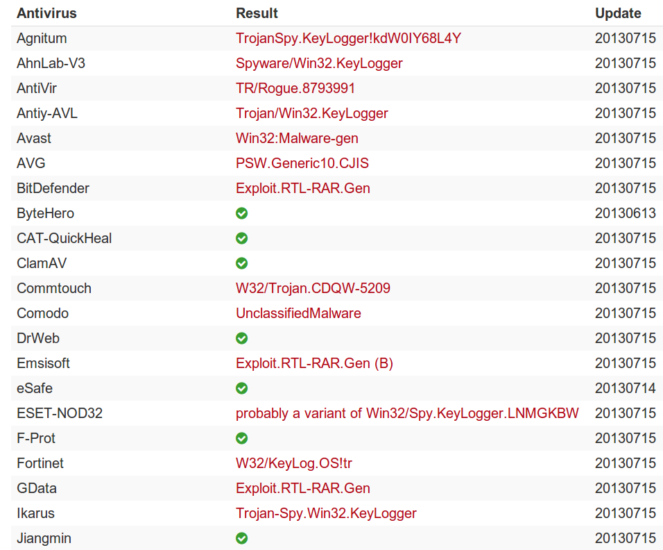
Anyhow, handing the entire RAR archive to VirusTotal produces the expected result:
VirusTotal – Product Pics malware file
It’s disconcerting to see ClamAV asleep at the switch on this one, but signature detection has become decreasingly relevant these days.
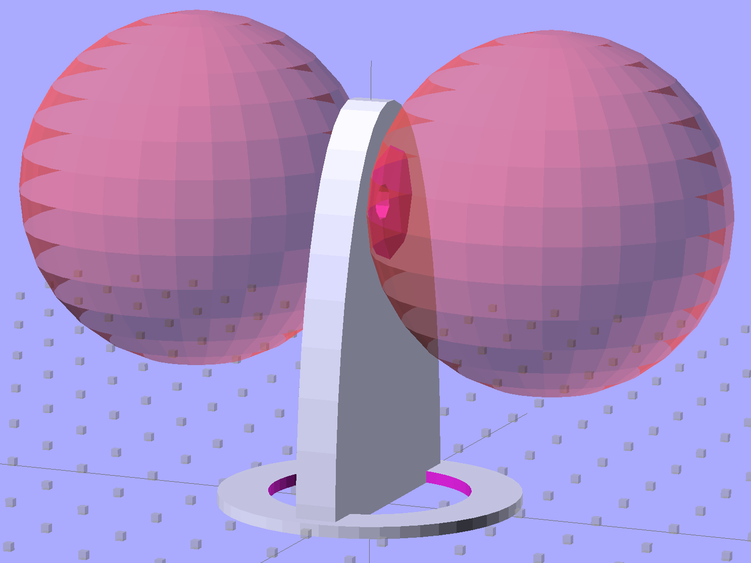
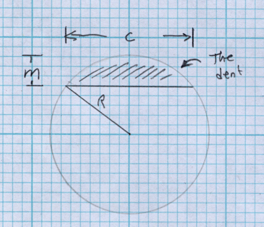
Then generate the sphere (well, two spheres, one for each dent) and offset it to scoop out the dent:
for (i=[-1,1]) {
	translate([i*(DentSphereRadius + HandleThick/2 - DentDepth),0,StringHeight])
		sphere(r=DentSphereRadius);
HandleThick controls exactly what you’d expect. StringHeight sets the location of the hole punched through the handle for a string, which is also the center of the dents.
The spheres have many facets, but only a few show up in the dent. I like the way the model looks, even if the facets don’t come through clearly in the plastic:
Quilting circle template – handle dent closeup – solid model
It Just Works and the exact math produces a better result than by-guess-and-by-gosh positioning.
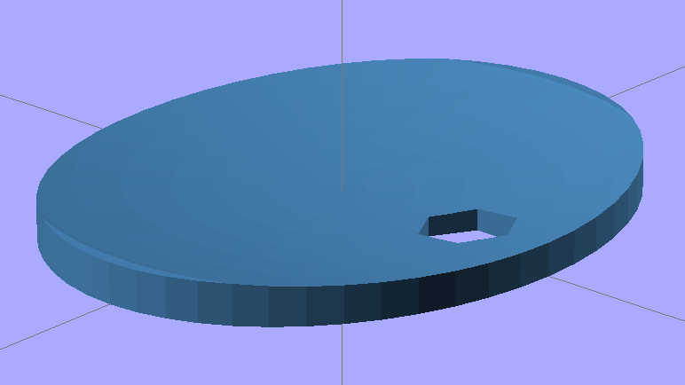
The sphere radius will come out crazy large for very shallow dents. Here’s the helmet plate for my Bicycle Helmet Mirror Mount, which has an indentation (roughly) matching the curve on the side of my bike helmet:
Helmet mirror mount – plate
Here’s the sphere that makes the dent, at a somewhat different zoom scale:
Helmet mirror mount – plate with sphere
Don’t worry: trust the math, because It Just Works.
You find equations like that in Thomas Glover’s invaluable Pocket Ref. If you don’t have a copy, fix that problem right now; I don’t get a cut from the purchase, but you’ll decide you owe me anyway. Small, unmarked bills. Lots and lots of small unmarked bills…
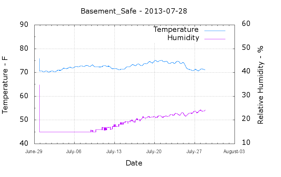
The humidity in the basement safe started rising this month:
Basement Safe – 2013-07-28
The bag of new silica gel weighed 575 g, so it adsorbed about 67 g of water as the humidity rose from bone dry to 24%. Last month it had soaked up 31 g, so the safe admits nearly an ounce of water each month with 50% RH in the basement. It takes five months to accumulate 60-ish g of water during the winter.
According to the Sorbent Systems charts, silica gel’s equilibrium capacity at 24% is about 12% of the gel’s weight, which would work out to 60 g. That’s close enough, methinks, given the graph resolution; the humidity changes slowly enough that it’s sorta-kinda equilibrated in there… 67 g works out to 13.4% of the dry weight, which is in the same ballpark.
I made up three more bags of dry gel (500 g + 7 or 8 g tare), tossed one in the safe, one in the 6 gallon plastic bucket of 3D printer filament, and one in an empty 6 gallon bucket for comparison. Some 6 dot (10-through-60%) humidity indicator cards are on their way, seeing as how I don’t have nearly enough dataloggers to keep up with the demand…