
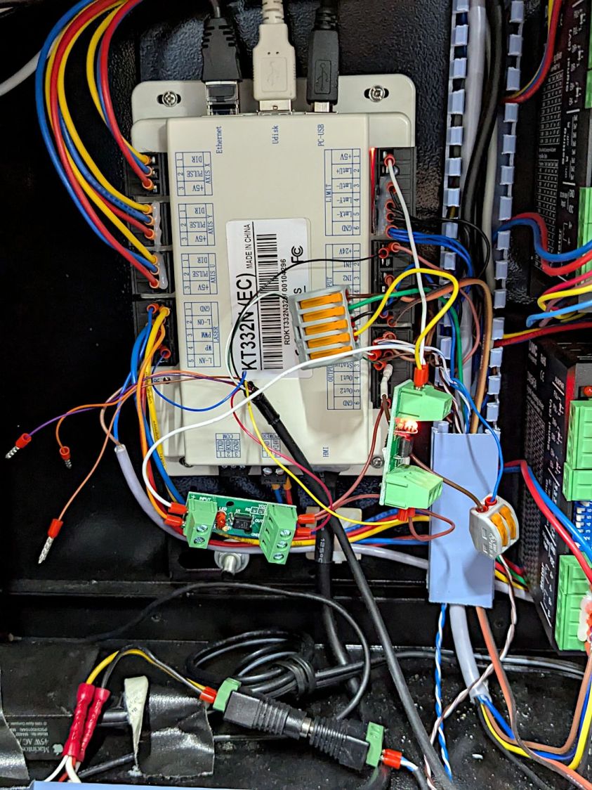
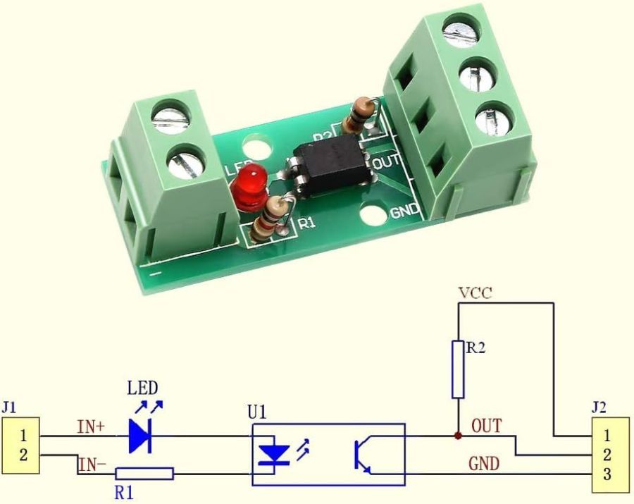
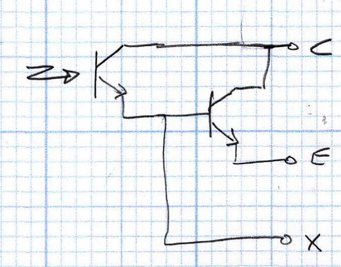
Rather than let the boosted optoisolators flop around:
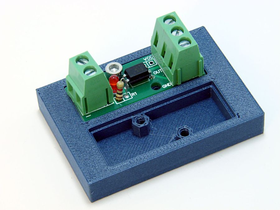
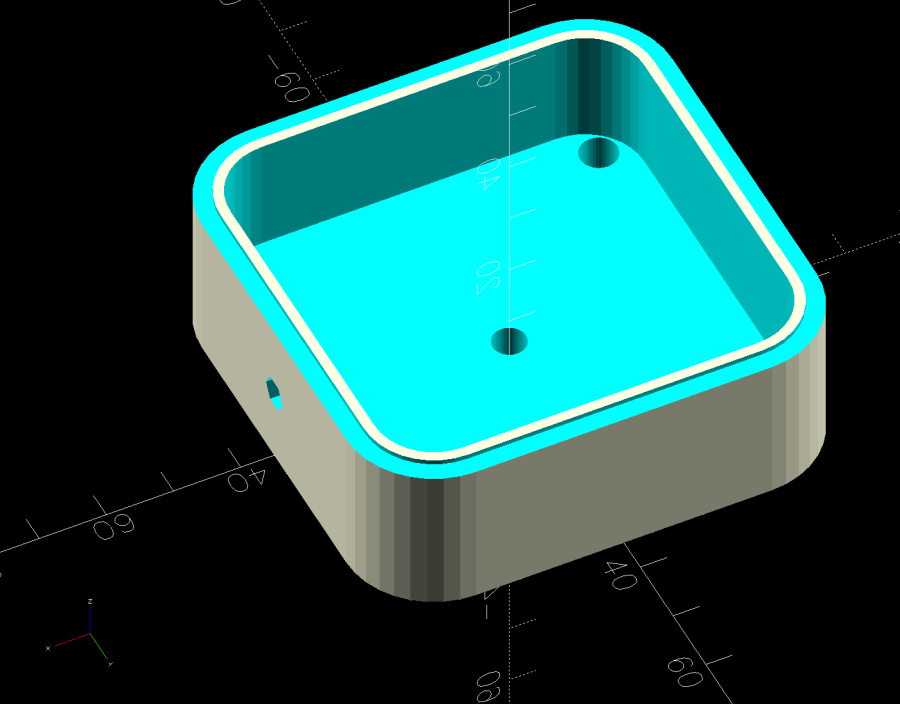
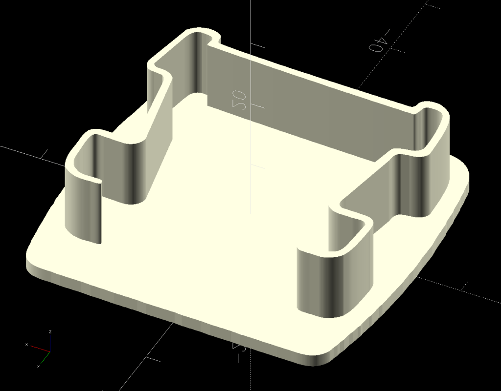
A small case seemed like a Good Idea™:
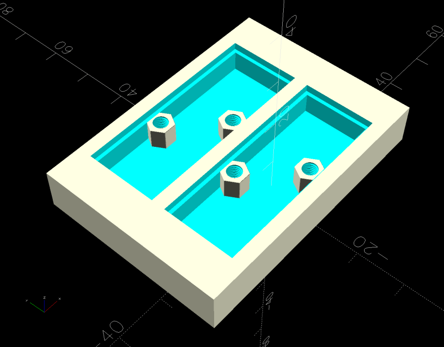
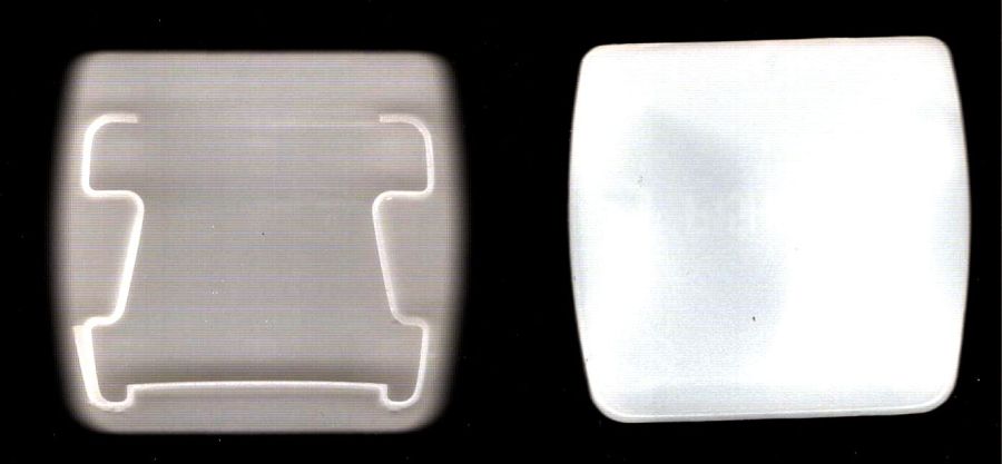
The little hex standoffs have M3 threads, although 6 mm screws are about as much as they’ll take. The recesses have clearance for the boost transistor underneath the PCB, but it’s your responsibility to not let random wires get in trouble with the exposed circuitry:
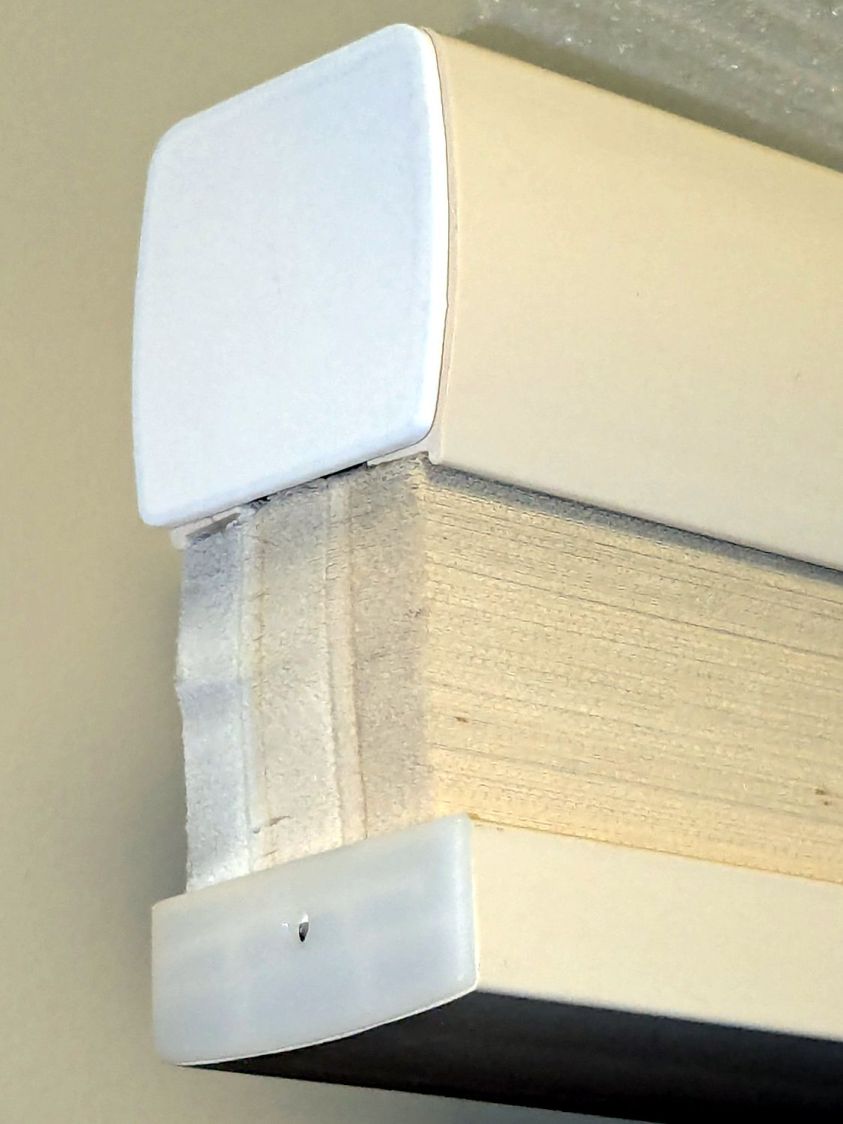
A strip of good foam tape sticks it to the controller:
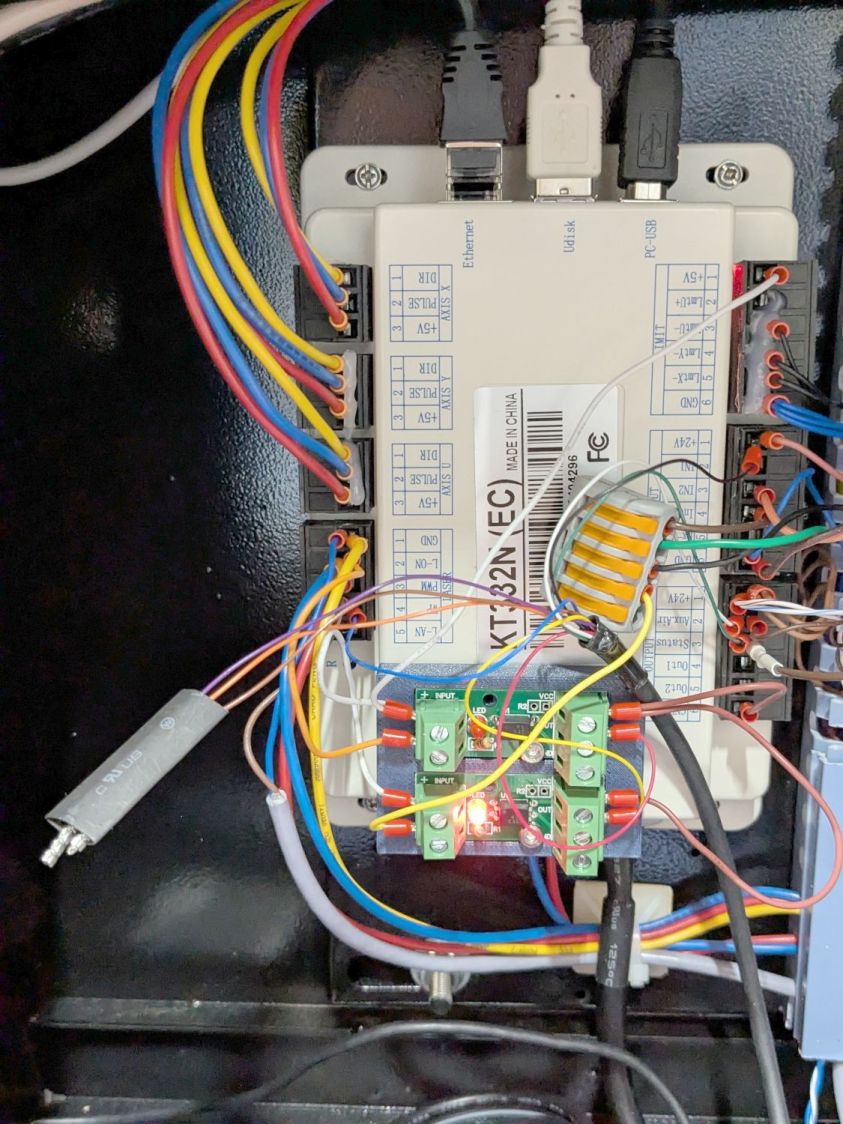
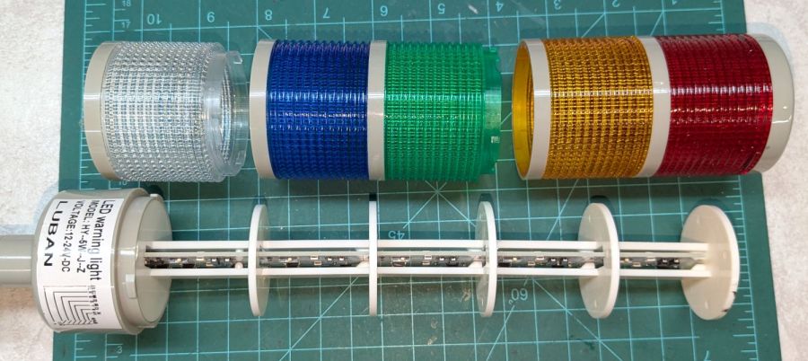
Admittedly, the stack light wiring remains something of a hairball, but it’s in a good cause.
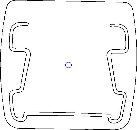
The OpenSCAD code can build as many cavities as you need:

The OpenSCAD source code as a GitHub Gist:
This file contains hidden or bidirectional Unicode text that may be interpreted or compiled differently than what appears below. To review, open the file in an editor that reveals hidden Unicode characters.
Learn more about bidirectional Unicode characters
| // Optoisolator case | |
| // Ed Nisley – KE4ZNU | |
| // 2025-01-09 | |
| include <BOSL2/std.scad> | |
| include <BOSL2/threading.scad> | |
| // Number of isolator mounts | |
| NumMounts = 2; | |
| /* [Hidden] */ | |
| Protrusion = 0.1; | |
| PCB = [40.5,15.5,1.6]; // optoisolator PCB | |
| LipWidth = 0.8; // support lip under PCB | |
| Margin = [8.0,3.0,4.5]; // clearance around PCB | |
| BaseThick = 3.0; // underneath | |
| Block = PCB + [2*Margin.x, 2*Margin.y, (Margin.z + BaseThick)]; | |
| echo(Block = Block); | |
| HolesOC = [9.5,10.0]; // M3 mounting holes (upper left / lower right) | |
| $fn = 3*4; | |
| //———- | |
| // Construct one mount | |
| module Mount() { | |
| union() { | |
| difference() { | |
| cube(Block,anchor=BOTTOM); | |
| up(Block.z – PCB.z) | |
| cube(PCB + [0,0,Protrusion],anchor=BOTTOM); | |
| up(BaseThick) | |
| cube(PCB – 2*[LipWidth,LipWidth,0] + [0,0,Block.z],anchor=BOTTOM); | |
| } | |
| for (i=[-1,1]) | |
| translate([i*HolesOC.x/2,-i*HolesOC.y/2,BaseThick]) | |
| threaded_nut(5.0,3.1,Margin.z,0.5, // flat size, root dia, height, pitch | |
| bevel=false,ibevel=false,anchor=BOTTOM); | |
| } | |
| } | |
| //———- | |
| // Mash together as many mounts as needed | |
| union() | |
| for (j=[0:(NumMounts – 1)]) | |
| back(j*(Block.y – Margin.y)) | |
| Mount(); |


