Ed Nisley's Blog: Shop notes, electronics, firmware, machinery, 3D printing, laser cuttery, and curiosities. Contents: 100% human thinking, 0% AI slop.
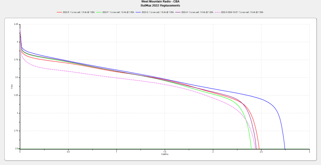
Although the total capacity remains about the same as before, the voltage depression causes the camera (which expects to run from a high-voltage lithium cell) to crash immediately after the car’s USB power jack shuts off, preventing it from properly closing the video file.
Another Batmax battery from the same batch works fine, so we’ll see if it can survive for another year.
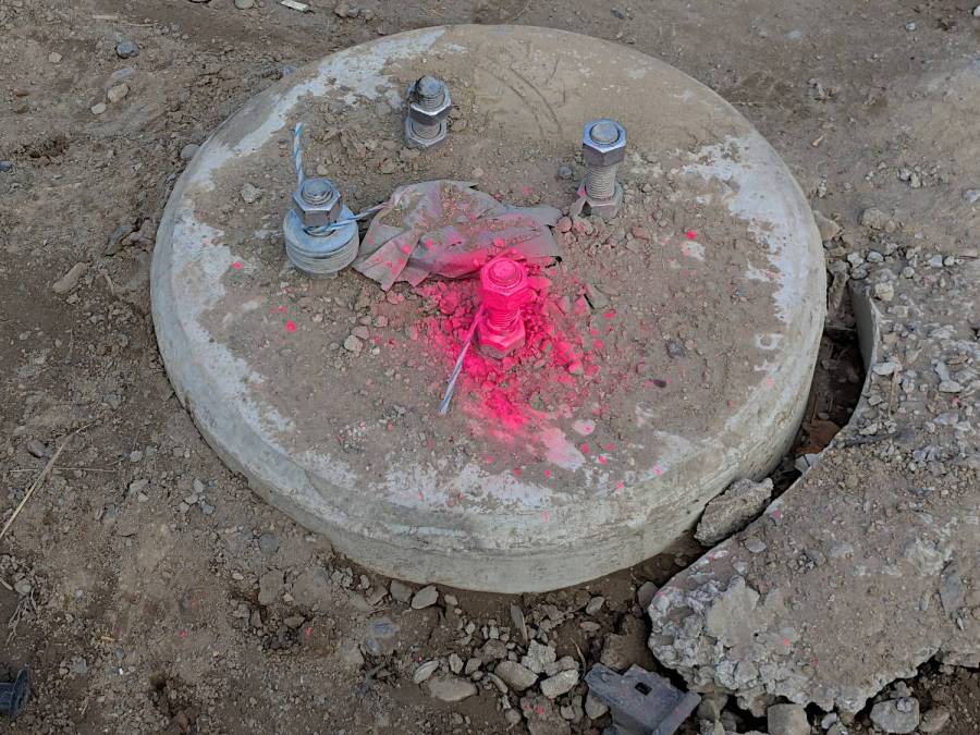
NYS DOT installed rows of street lamp foundations along both sides of Rt 376 as part of the intersection reconstruction that will eventually put a fourth traffic circle along Raymond Avenue. Until the intersection of Rombout House Lane with Rt 376 vanishes, this lamp base at the corner sits well within the turning radius of the heavy trucks entering & exiting the contractor’s material dump & equipment marshalling yard:
Street Lamp Base – A
The fluorescent paint appeared after something heavy ran over the base and bent two of the bolts that should secure the lamp post.
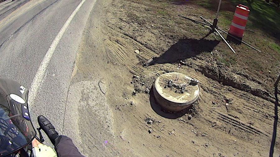
A few days and a few more passes killed those bolts dead:
Street Lamp Base – A – more destruction
The barrier barrel in the background sat atop the base for a few days, but obviously didn’t affect the outcome.
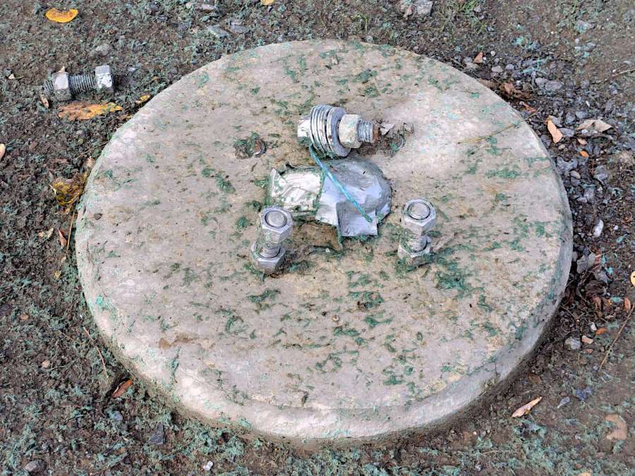
A few hundred feet south, a heavy metallic mass sheared off another pair of bolts and bent the survivors:
Street Lamp Base – B
Someone eventually moved the sheared bolt atop the base, so perhaps the damage has been noted where that note will have some effect.
The “bolts” are the threaded end of long rods embedded in the three or four feet of pre-cast concrete forming the lamp base. The concave concrete mass to the right in the first picture is residue from the poured concrete in the hole anchoring the base to the ground.
A four foot deep trench along the row of lamps holds electrical conduit between them for the wiring that will eventually surface through the conduit covered by the duct tape. The white-and-blue cord hauls the pull tape from one base to the next to pull the conductors through the conduit.
Replacing those cast-in-place bases won’t be a trivial (pronounced “inexpensive”) operation and I suspect a powerful motivation to just un-bend the wounded bolts and pretend they’re not severely weakened. I doubt a base with just two bolts will pass final inspection, but maybe the inspector won’t look inside the lamp pole covers.
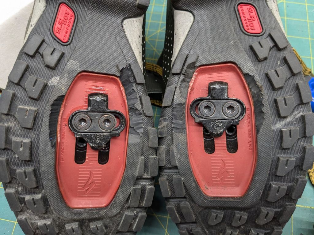
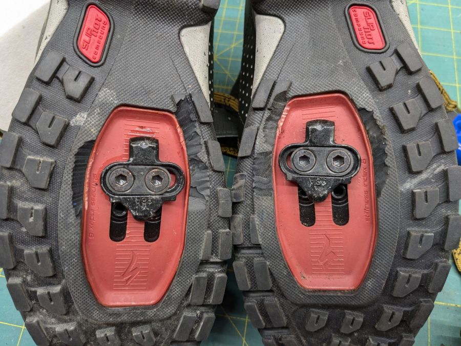
As before, the sole & lugs on Mary’s new Specialized cycling shoes requires too much torque to release the cleat, so I once again carved off everything that got in the way:
Cycling shoe sole carving
A field test prompted a little more carving, but you get the general idea.
This surely affects the shoes’ lateral stability, but getting her feet out of the cleats when & where needed outweighs everything else.
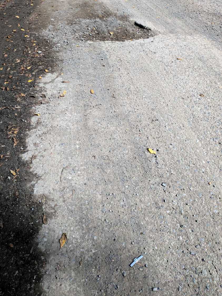
Spotted while walking on Rombout House Lane out of the Vassar Preserve:
Pothole vs wheel weight
Looks like somebody hit that pothole at a pretty good clip and knocked a wheel weight loose.
Rombout House Lane is a tiny L-shaped road serving as a Preserve entrance and exit not at the intersection of Rt 376 / Raymond / Hooker, but it’s slated for oblivion when NYS DOT finishes constructing the roundabout / rotary. With plenty of heavy equipment now crushing it, a walking pace is as fast as anyone should drive (or bicycle!) there.
Being an Old Guy, I lift dumbbell weights after bike rides for load-bearing upper-body exercise, but need a few more dumbbell nuts (a.k.a. “collars”) to simplify adjusting the weights for each set. Such things are commercially available, but the reviews suggest abysmally bad thread QC and a high return rate.
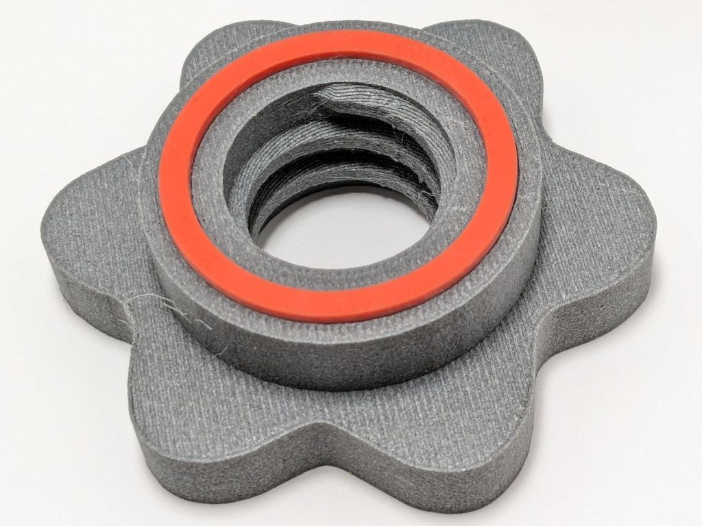
Given that I treat my toys carefully, this should suffice:
Dumbbell Nut – finished
Start with a scan of a steel nut in GIMP:
Dumbbell Nut – scan
Blow out the contrast, trace it, smooth out some irregularities, get a mask:
Dumbbell Nut – mask
Select by color, convert the selection to a path, save as SVG, import into OpenSCAD, add a nut with threads from the incomparably useful BOSL2 library, extrude a few features, and this pops out:
Dumbbell Nut – solid model
Run it through PrusaSlicer, print on the MK4, and iterate a few times to get everything right:
Dumbbell Nut – test pieces
I naively thought the threads were something standard like Acme, but they’re full-frontal custom trapezoidal. I knew the first pass would be wrong, so the small hex nut on the left started the whole process. Upper left is a revised Acme thread with all the other features, lower middle is the custom trapezoidal thread, and the nut on the upper right worked. Make three more, just like the first one, enjoying the magic of 3D printing.
Draw the bumper washer in LightBurn based on the dimensions in the OpenSCAD code, cut a set from stamp-pad rubber & adhesive sheet, then assemble:
Dumbbell Nut – assembly
As the saying goes, we got nuts:
Dumbbell Nut – installed
The gray PETG-CF looks black against a white background and gray against black iron.
With a set of precisely fitting nuts in hand, I discovered one of the four bars in my weight sets is slightly larger than the others, so the code now produces an embiggened root diameter and I have two spares.
The garden hose leading from the standpipe / hose bibs outside Mary’s garden to her drip irrigation plumbing has an octagonal fitting requiring more torque than her hand can easily produce. I offered to make a larger grip for the fitting, which amounts to a disk with a grippy rim sized to her hand and an interior opening suitable for gluing to the fitting.
A couple of laser-cut MDF sizing prototypes accompanied me to the garden:
Hose Fitting Grip – MDF prototype
The springy fingers around the fitting soak up the inevitable distortions found in a battered hose and will eventually be filled with adhesive to lock the grip in place.
MDF being obviously the wrong material for a permanent installation, the final grip will be 3D printed, with the LightBurn layout modified to produce the internal structure:
Hose Fitting Grip – LightBurn layers
From left to right:
The stacked pieces in order of printing
Main grip with springy fingers
Spacer keeping the fingers away from the narrower opening
Support layer
Narrow opening to align the grip with the end of the fitting
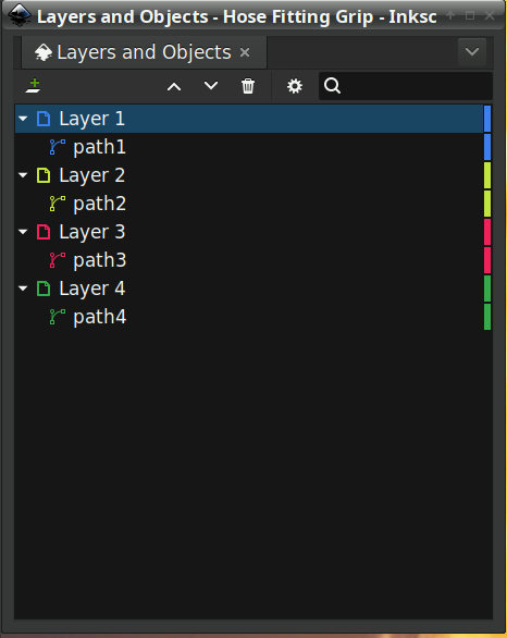
Exporting the SVG images and making a bank shot off Inkscape to create layer names:
Hose Fitting Grip – Inkscape layers
The ascending layer name + numbers allow a simple OpenSCAD program to extract the SVG shapes by name, extrude them to the proper thickness, put them at the proper height, then combine the result:
The hideous mess generating the Level vector happens because OpenSCAD does not have mutable variables and I hate retyping numbers. One can use a recursive function to add the values, but copypasta makes more sense in this case.
Which produces this solid model, with garish colors for pedagogic purposes:
Hose Fitting Grip – top – solid model
The thin yellow band will be one thread thick to provide support for the green layer with a smaller ID than the springs below it. The gray layer below the yellow is the air gap above the springs.
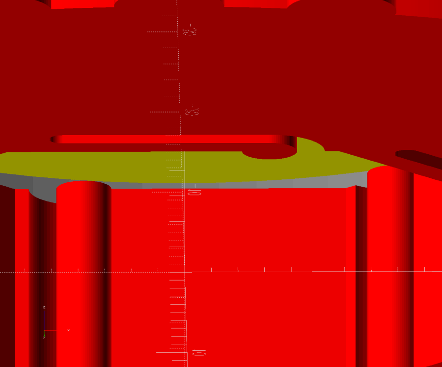
Peering inside the bottom shows the (gray) layer providing clearance between the springs and the (yellow) support layer:
Hose Fitting Grip – bottom interior – solid model
Exporting the model as a 3mf file, importing it into PrusaSlicer, and slicing it with suitable parameters (Extrusion Multipler = 0.8) does what you’d expect. This top view shows the internal structure just below the support bridge across the middle:
Hose Fitting Grip – spring detail – PrusaSlicer
Printing it in gray PETG-CF was uneventful, with the bridging layer coming out surprisingly well:
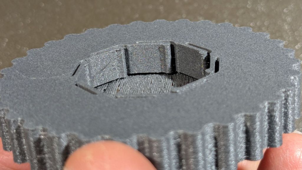
Hose Fitting Grip – as printed
The springs definitely have an air gap in there:
Hose Fitting Grip – printed interior
And the support layer cuts out neatly with an Xacto knife:
Hose Fitting Grip – support removed
We’ve had enough rain over the last few days (something to do with a continental-scale storm) to keep me and my adhesives out of the garden, but it hasn’t needed any watering, either.
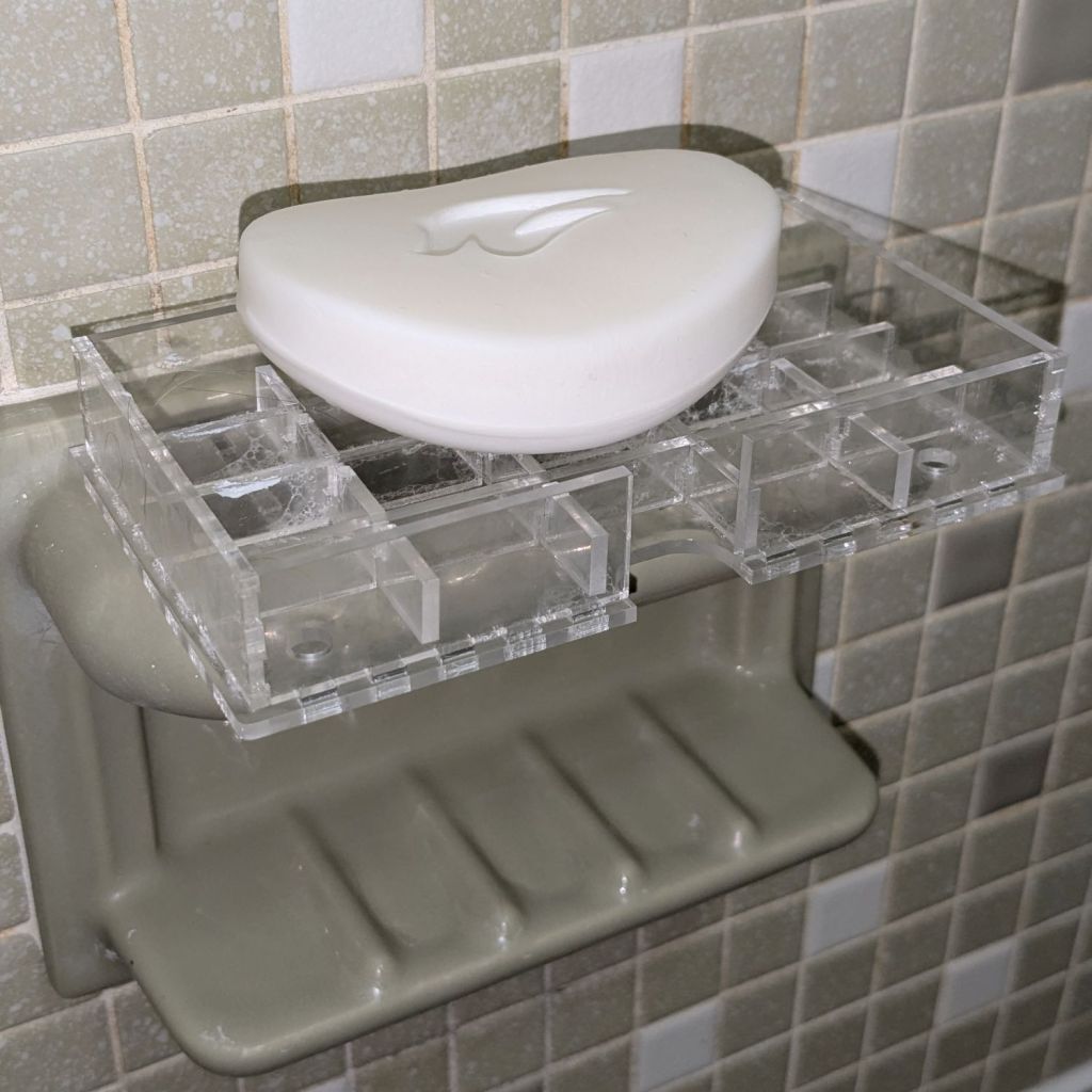
As expected, the adhesive foam strips I used on the bathtub soap tray didn’t survive continued exposure to hot soapy water, so Version 2 includes hooks securing it to the ceramic soap tray and a few other tweaks:
Bathtub Soap Tray – V2 – LightBurn layout
The view from the top:
Soap Tray V2 – top
The hooks are more visible from the bottom, as is the 10 AWG copper wire preventing the whole affair from rotating around the ceramic handle from the weight of the soap bar:
Soap Tray V2 – bottom
Ignore the usual crud you’ll find on your ceramic soap tray, too.


