Ed Nisley's Blog: Shop notes, electronics, firmware, machinery, 3D printing, laser cuttery, and curiosities. Contents: 100% human thinking, 0% AI slop.
Mary’s compadres sometimes send her pictures of garden vegetables and quilting projects. Those pictures usually pass through Microsoft Outlook (or its ilk) and emerge in winmail.dat files that aren’t particularly useful in a Linux context. That page gives a good overview of the problem and how to resolve it; I’m just documenting the process here, so I can find it again.
Start by installing both tnef and convmv. I think the latter isn’t needed in our situation, because most folks use flat ASCII file names that come through just fine.
Save the attachment in, say /tmp and unleash tnef on it:
cd /tmp
tnef --file=winmail.dat
That unpacks all the attachments into /tmp, where one may have one’s way with them.
It’s not worth my effort to bolt that into the email programs and then maintain that mess across updates, so we’ll do it by hand as needed.
Microsoft certainly had a good reason for inventing Yet Another Encapsulation Format, although I wonder why good old ZIP wouldn’t have worked nearly as well…
Just like fire extinguishers and bike helmets, you never know when you’ll need to use this thing in a hurry… then it’s too late to clean out all the crap that accumulates on any flat (or concave) spot.
Not that I’m completely innocent, of course.
The DSC-H5 had been outdoors for a few hours, hiking with us at 25 °F, so the lens fogged instantly when we walked through the greenhouse door.
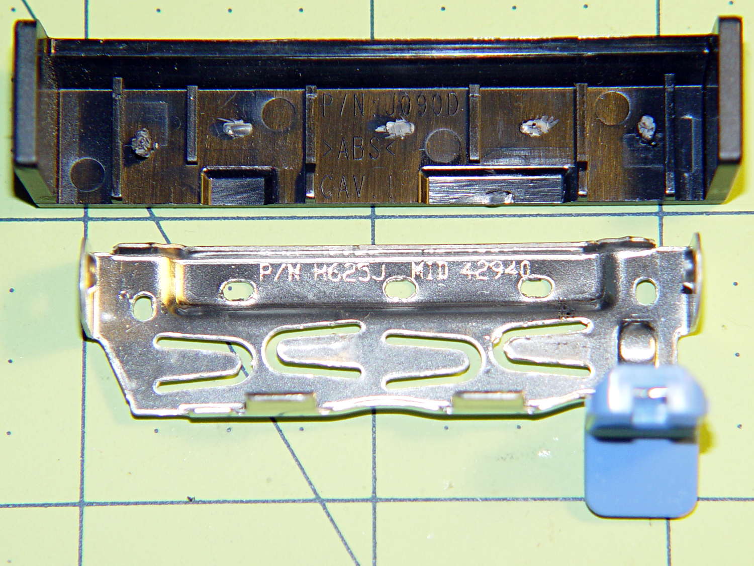
The new-to-me Optiplex 980 has a tool-free clamp securing the PCI card brackets to the chassis, with a nice plastic dress cover that really finishes off that side of the case. Alas, it’s secured by five small heat-staked plastic pegs that I managed to shear off as part of a finger fumble that you’ll recognize when it happens to you and which I need not further discuss:
Optiplex 980 PCI Clamp Cover – disassembled
So I drilled two slightly undersized holes for the tiniest screws in the Little Box o’ Tiny Screws:
Optiplex 980 PCI Clamp Cover – drilling
The two end plates sticking up are the only square parts of the cover, so that thing is actually clamped by the right-side plate and sheer will power. I ran the drill down 3 mm from the top of the post at the slowest manual jog speed from the Joggy Thing and I did not break through the top and did not hit that lathe bit under the cover.
The screw threads and a dab of epoxy hold them in place:
Optiplex 980 PCI Clamp Cover – tiny screws
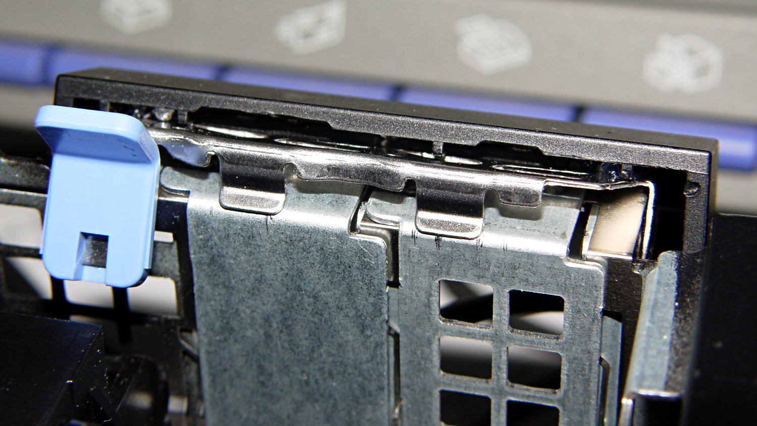
I’d like to say the finished repair looked like this:
Optiplex 980 PCI Clamp Cover – in place
But, alas, the eagle-eyed reader will note that the screws are gone, replaced by two dabs of clear acrylic caulk; those faint threads and epoxy were no match for the snap of that latching lever and the slight distortion caused by the spring fingers applying force to the brackets.
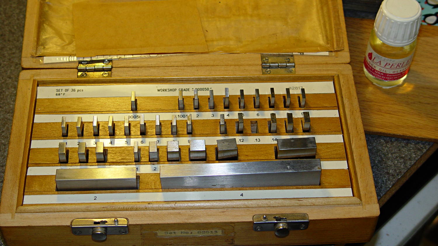
Turns out that it’s 0.1340 inches, determined by bracketing the sliver above that 0.1300 block with feeler gauges. I don’t believe that last zero, either, as the Basement Shop was about 10 °F below the block’s 68 °F calibration temperature. [grin]
The actual size of that gap makes absolutely no difference whatsoever, but fooling around with the gauge blocks gave me an excuse to renew my acquaintance with them and, en passant, massage some oil over their long-neglected bodies:
Gauge block set
I used La Perle Clock Oil, which isn’t Official Gauge Block Oil, but doesn’t go bad on the shelf. Verily, this bottle may be the last of its kind, as it’s no longer available from any of the usual sources; it appears I bought it back in 2000.
The blocks are in good shape, probably because they don’t often see the light. FWIW, I have experimentally determined that my body oil doesn’t etch fingerprints into steel.
The block set, which is similar to a current box o’ blocks from Enco, claims “Workshop Grade”, but the ±0.00050 inch = 1.27 μm tolerance shown in the top row of the labels is much worse than even grade B’s sub-micron tolerance. That newer box claims “Economy” accuracy with the same spec, so I suppose somebody kvetched about mis-using the terms.
Ah, well, they’re far better than any measurements I’ve needed in a while and entirely suitable for verifying my other instruments.
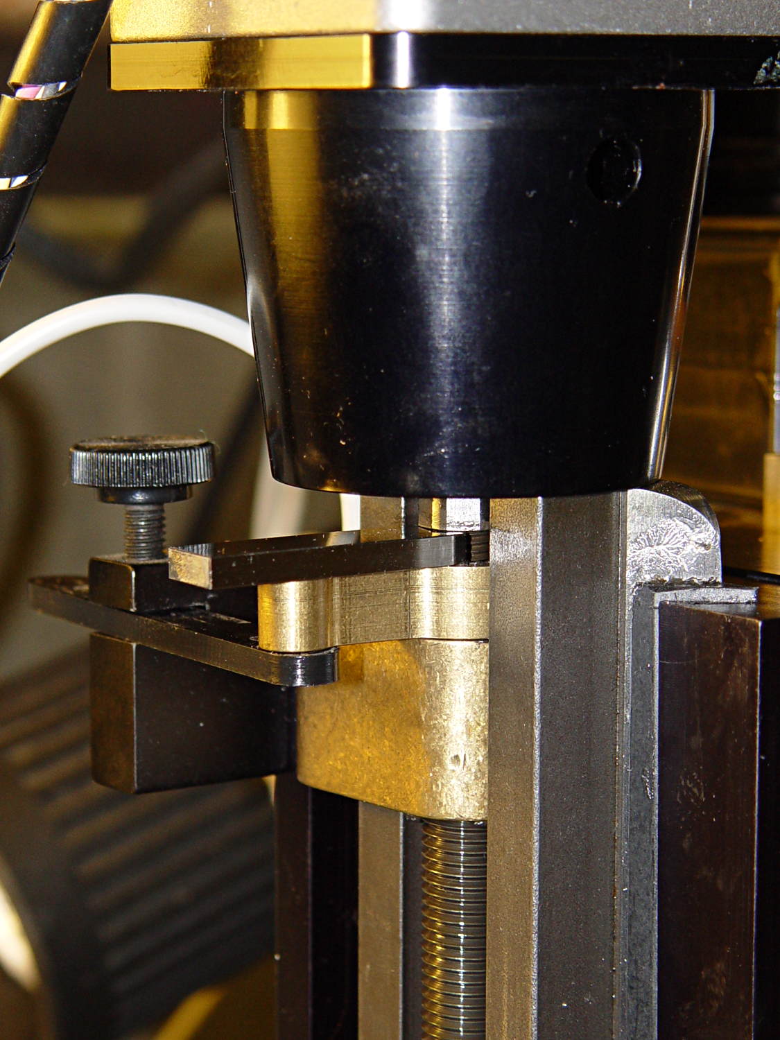
Turns out that I managed to crunch it, exactly as I expected: I’d added a block to the Z-axis stage that poked the home switch just slightly before the anti-backlash nut unscrewed from the top of the leadscrew, but the stage could continue moving another few millimeters.
You can see the gap just above the brass anti-backlash nut:
Sherline Z-axis leadscrew nut – top end
At that point, the nut has barely a single micro-smidgen of thread engaged; that last 0.1340 inch of travel (yeah, I measured it) isn’t usable.
Rather than put a collar around the end of the leadscrew, I opted for a brute-force block atop the Z-axis saddle nut that will slam into the bottom of the stepper motor mount just before the anti-backlash nut disengages:
Sherline Z-axis Overrun Block – rear view
A strip of tapeless sticky (double-sided tape, minus the tape) holds the block in place on the saddle nut. It’s not subject to any particular stress: as long as it doesn’t fall off, it’s all good.
I ran the stage upward until it stalled, then epoxied a new switch (with the old fluorescent tape) in place. This shows the result after backing the stage down a few millimeters:
Sherline Z-axis Overrun Block – side view
The solid model shows off the bevel that provides a bit more room for anti-backlash nut adjustment, not that I ever adjust it that much:
Sherline Z-Axis Overrun Prevention Block – solid model
Obviously, it doesn’t print in that position, but it’s easier to design it in the natural orientation and flip it around for printing.
The OpenSCAD source code:
// Sherline Z-axis Overrun Prevention Block
// Ed Nisley KE4ZNU December 2013

Layout = "Show";			// Show Build

//- Extrusion parameters must match reality!
//  Print with 2 shells and 3 solid layers

ThreadThick = 0.25;
ThreadWidth = 0.40;

HoleWindage = 0.2;

Protrusion = 0.1;			// make holes end cleanly

//----------------------
// Dimensions

BlockZ = 30.0;				// overall height
ZLimit = 17.0;				// Z travel limit

TongueX = 9.0;				// beside Z axis dovetail
TongueY = 10.0;

StubX = 6.0;				// behind Z axis pillar
StubY = 3.0;

BlockX = TongueX + StubX;	// overall X

TabY = 3.0;					// behind brass bracket
TabX = BlockX - sqrt(2)*TabY;
TabZ = BlockZ - ZLimit;

BlockY = TongueY + StubY + TabY;	// overall Y

//----------------------
// Useful routines

module ShowPegGrid(Space = 10.0,Size = 1.0) {

  Range = floor(50 / Space);

	for (x=[-Range:Range])
	  for (y=[-Range:Range])
		translate([x*Space,y*Space,Size/2])
		  %cube(Size,center=true);

}

//- The Block

module Block() {

	difference() {
		cube([BlockX,BlockY,BlockZ]);

		translate([-Protrusion,-Protrusion,-Protrusion])	// remove column
			cube([(StubX + Protrusion),(TongueY + Protrusion),2*BlockZ]);

		translate([-BlockX/2,-Protrusion,-Protrusion])		// form tab
			cube([2*BlockX,(TongueY + StubY),(TabZ + Protrusion)]);

		translate([0,BlockY,(BlockZ/2 - 0*Protrusion)])
			rotate(45)
				cube([3*StubY,2*StubY,(BlockZ + 2*Protrusion)],center=true);

		translate([0,0,-Protrusion])
			cube([sqrt(2)*TabY,2*BlockY,(TabZ + Protrusion)]);
	}
}

//-------------------
// Build it...

ShowPegGrid();

if (Layout == "Show")
	Block();

if (Layout == "Build")
	translate([-BlockZ/2,-BlockY/2,BlockX])
	rotate([0,90,0])
		Block();
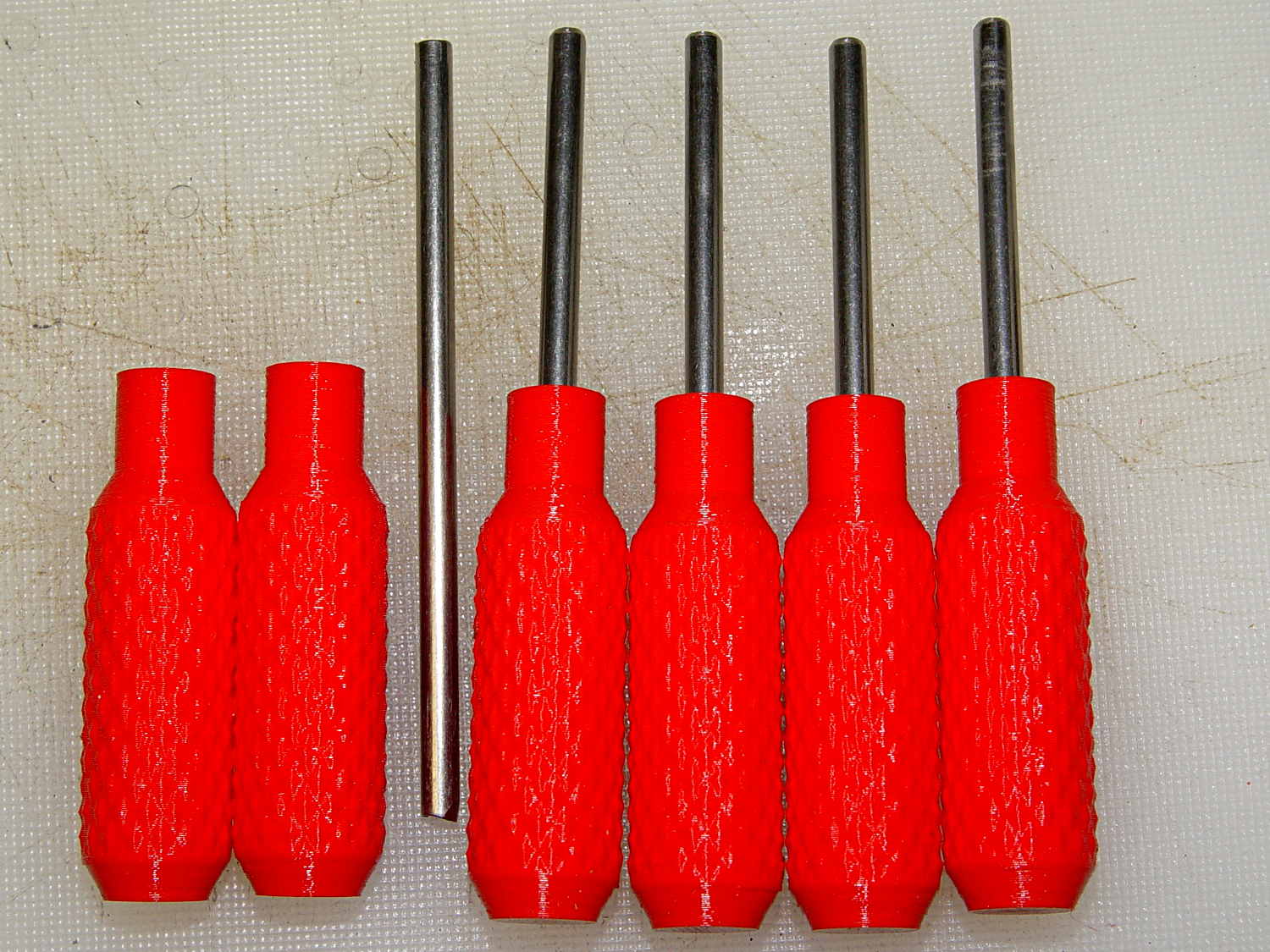
While putting the speed wrenches in the box with the Sherline four-jaw chuck, it occurred to me that I had all the makings of a handle for Sherline’s steel tommy bars:
Sherline Tommy Bar Handle – solid model
Because these are intended for pushing, rather than twisting, I dialed the knurl back to 32 DP, reduced the depth to 0.5 mm, and ran the bar almost all the way through the handle for strength:
Sherline Tommy Bar Handles
A dab of urethane adhesive inside the handle holds the bar in place. They started out a snug slip fit, so we’ll see how well that holds the bars in place.
A tommy bar holds the spindle against the torque from the collet pusher:
Sherline CNC mill – tommy bar and collet pusher
A pair will come in handy with the three-jaw chuck the next time that one appears.
The white slab is a very early 3D printed tool from my Thing-O-Matic, made to hold the pin at exactly the proper distance from the pulley so it fits squarely into the pusher and locks it to the spindle:
Locking pin holder – spindle end view
Other folks make much nicer tommy bar handles than mine, but I’d say my 3D printed handles beat a common nail any day!
The OpenSCAD source code:
// Knurled handles for Sherline tommy bars
// Ed Nisley - KE4ZNU - December 2013

use <knurledFinishLib_v2.scad>

//- Extrusion parameters must match reality!
//  Print with 2 shells and 3 solid layers

ThreadThick = 0.20;
ThreadWidth = 0.40;

HoleWindage = 0.2;			// extra clearance

Protrusion = 0.1;			// make holes end cleanly

PI = 3.14159265358979;
inch = 25.4;

//----------------------
// Dimensions

ShaftDia = 10.0;				// un-knurled section diameter
ShaftLength = 10.0;				//  ... length

SocketDia = 4.0;				// tommy bar diameter
SocketDepth = 40.0;

KnurlLen = 35.0;				// length of knurled section
KnurlDia = 15.0;				//   ... diameter
KnurlDPNom = 32;				// Nominal diametral pitch = (# diamonds) / (OD inches)

DiamondDepth = 0.5;				//   ... depth of diamonds
DiamondAspect = 2;				// length to width ratio

NumDiamonds = floor(KnurlDPNom * KnurlDia / inch);
echo(str("Num diamonds: ",NumDiamonds));

NumSides = 4*(NumDiamonds - 1);		// 4 facets per diamond. Library computes diamonds separately!

KnurlDP = NumDiamonds / (KnurlDia / inch);				// actual DP
echo(str("DP Nom: ",KnurlDPNom," actual: ",KnurlDP));

DiamondWidth = (KnurlDia * PI) / NumDiamonds;

DiamondLenNom = DiamondAspect * DiamondWidth;					// nominal diamond length
DiamondLength = KnurlLen / round(KnurlLen/DiamondLenNom);		//  ... actual

TaperLength = 0.75*DiamondLength;

//----------------------
// Useful routines

module PolyCyl(Dia,Height,ForceSides=0) {			// based on nophead's polyholes

  Sides = (ForceSides != 0) ? ForceSides : (ceil(Dia) + 2);

  FixDia = Dia / cos(180/Sides);

  cylinder(r=(FixDia + HoleWindage)/2,
           h=Height,
           $fn=Sides);
}

module ShowPegGrid(Space = 10.0,Size = 1.0) {

  Range = floor(50 / Space);

	for (x=[-Range:Range])
	  for (y=[-Range:Range])
		translate([x*Space,y*Space,Size/2])
		  %cube(Size,center=true);
}

//- Build it

ShowPegGrid();

difference() {
	union() {
		render(convexity=10)
		translate([0,0,TaperLength])
			knurl(k_cyl_hg=KnurlLen,
				  k_cyl_od=KnurlDia,
				  knurl_wd=DiamondWidth,
				  knurl_hg=DiamondLength,
				  knurl_dp=DiamondDepth,
				  e_smooth=DiamondLength/2);
		color("Orange")
		cylinder(r1=ShaftDia/2,
					r2=(KnurlDia - DiamondDepth)/2,
					h=(TaperLength + Protrusion),
					$fn=NumSides);
		color("Orange")
		translate([0,0,(TaperLength + KnurlLen - Protrusion)])
			cylinder(r2=ShaftDia/2,
					r1=(KnurlDia - DiamondDepth)/2,
					h=(TaperLength + Protrusion),
					$fn=NumSides);
		color("Moccasin")
		translate([0,0,(2*TaperLength + KnurlLen - Protrusion)])
			cylinder(r=ShaftDia/2,h=(ShaftLength + Protrusion),$fn=NumSides);

	}
	translate([0,0,(2*TaperLength + KnurlLen + ShaftLength - SocketDepth + Protrusion)])
		PolyCyl(SocketDia,(SocketDepth + Protrusion),6);
}