The Smell of Molten Projects in the Morning

Ed Nisley's Blog: Shop notes, electronics, firmware, machinery, 3D printing, laser cuttery, and curiosities. Contents: 100% human thinking, 0% AI slop.

Author: Ed

  • Victoreen 710-104 Ionization Chamber

    Using radiation to generate random numbers reminded me of some Victoreen 710-104 ionization chambers that have been in the pile basically forever:

    Victoreen 710-104 Ionization Chamber
    Victoreen 710-104 Ionization Chamber

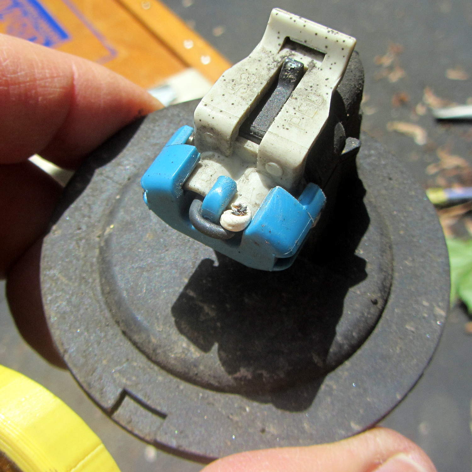
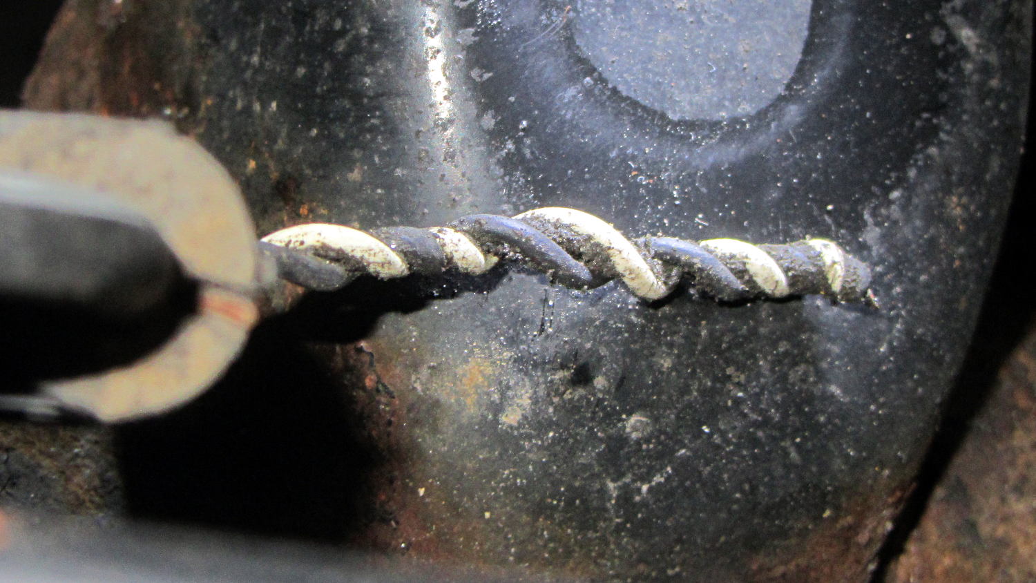
    The central contact seems to be double-insulated from the chamber with glass (?) seals in a soldered-in-place assembly:

    Victoreen 710-104 Ionization Chamber - terminal detail
    Victoreen 710-104 Ionization Chamber – terminal detail

    That might be rosin left over from soldering, but you’d think they would have rinsed it off to reduce the leakage. Some cleaning will be in order.

    A picture in The Fine Manual for the CD-V-710 Model 5 Radiation Survey Meter showed that the circuit board used point-to-point wiring, with the range switch soldered directly to that bent metal contact:

    Victoreen CD-V-710 Model 5 Manual - Page 10 - circuit layout
    Victoreen CD-V-710 Model 5 Manual – Page 10 – circuit layout

    Another page gave some useful values and a simplified schematic:

    Victoreen CD-V-710 Model 5 Manual - Page 5
    Victoreen CD-V-710 Model 5 Manual – Page 5

    Never fear, the manual also has the full schematic; they don’t write manuals like that any more.

    The chamber bias voltage was +22.5, from one carbon-zinc battery available back in the 1950s. You can still get 22.5 V batteries at about ten bucks a pop, but 24 V from a pair of cheap & readily available 12 V A23 alkaline batteries should be close enough. There’s no current drain, so the batteries should last their entire shelf life.

    The “HI-MEG” resistor represents a trio of glass-body resistors selected by the range switch:

    • R5 = 100 GΩ → 0.5 R/h
    • R6 = 10 GΩ→ 5 R/h
    • R7 = 1 GΩ→ 50 R/h

    As the saying goes, if you must select R7 in an actual emergency, you should sit down, put your head between your legs, and kiss your ass goodbye.

    The steel-wall chamber responds only to gamma radiation, with a nominal current of 5 pA at 0.5 R/h. However, given an op amp like the LMC6081 with 10 fA bias current, maybe building an electrometer-style amplifier that can respond to background gamma radiation or maybe secondary gamma rays from cosmic ray air showers would be feasible; I haven’t done anything like that in a while and even a faceplant would be interesting.

    Alas, radium-226 and its progeny, including radon-222 decay through alpha and beta emission that’s specifically excluded by the can.

    This is not a new idea, by any means, as shown by some extensive discussion and well-done circuitry. Any amplifier that works with the Victoreen can will certainly work with a homebrew ionization chamber.

  • Sony HDR-AS30V: Still Image Quality

    Although I got the Sony HDR-AS30V action camera for my bike helmet and don’t like its aggressive video compression, it has the optics for good still pictures (clicky for more dots):

    Walkway South View - Sony HDR-AS30V still image
    Walkway South View – Sony HDR-AS30V still image

    A dot-for-dot crop from the middle at full size:

    Walkway South View - Sony HDR-AS30V still image - detail
    Walkway South View – Sony HDR-AS30V still image – detail

    The thing has absolutely no affordance for hand-holding, so perching it on the Walkway handrail 200 feet over the Hudson required tamping down my usual risk aversion.

    Both images have been slightly contrast-tweaked and lightly compressed from the original data, but not by enough to matter here. Generally, I apply ruthless compression to keep the image size under control, so these look a lot better than the usual pix around here.

  • 125 mm OD White LED Ring Current vs. Voltage

    I picked up a pair of 125 mm OD white LED rings for the hand magnifier project from the usual eBay source, which arrived with the expected level of build quality:

    LED Ring - SMD soldering
    LED Ring – SMD soldering

    But, hey, all the LEDs lit up more-or-less uniformly.

    With 20 mA in each of 13 parallel strings of 3 white LEDs, the ring should draw 260 mA. It’s nominally a 12 V device sorta-kinda intended for automotive “angel eye” use, where the actual battery charging voltage runs around 14 V. The 180 Ω ballast resistors seem to be sized with that in mind:

    LED Ring - SMD soldering
    LED Ring – SMD soldering

    The reciprocal of that 45.5 mA/V slope is 220 V/mA = 220 Ω, which is close enough to the actual (we presume from their marking) 180 Ω resistors for comfort.

    Driving it at 14 V to get 250 mA dissipates 3.5 W and makes it pleasantly warm.

    For use with a magnifying lens, I think it deserves a brightness control. Perhaps hacking a bigger trimpot with a knob onto a cheap & tiny boost converter will suffice.

  • Toyota Sienna: Rear ABS / Speed Sensor Failure

    Given a hint that the Sienna’s left rear ABS / speed sensor had failed, we took a look:

    Sienna ABS failure - removing lug nuts
    Sienna ABS failure – removing lug nuts

    She removed the wheel under field conditions using only in-the-car tools for practice, with the jack stand and wheel chock because we weren’t really beside the road. It turned out that breaking The Last Lug free required bouncing her full weight on the wrench handle, which is what we expected based on previous experience.

    Yes, I pointed out the inadequacy of that footwear. Yes, she loosened the lugs before jacking the van.

    With the van up, the first look showed the ABS diagnostic blink code was dead on:

    Sienna ABS failure - sensor cable
    Sienna ABS failure – sensor cable

    That bit of tubing in her fingers should contain a pair of wires, which was a bit of a puzzle.

    The connector remained snapped onto the sensor head, but the whole affair came out easily enough:

    Sienna ABS failure - connector on sensor head
    Sienna ABS failure – connector on sensor head

    We thought those wires seemed very tightly twisted, too. I guessed that a clip holding the sensor head in place had gone missing, allowing it to rotate in place.

    Which was partially true, as the “missing” wires were very very very tightly twisted inside that flexible tubing and, thus, much shorter than they should be:

    Sienna ABS failure - hypertwisted sensor cable
    Sienna ABS failure – hypertwisted sensor cable

    Lining up the removable parts:

    Sienna ABS failure - sensor head disassembly
    Sienna ABS failure – sensor head disassembly

    The sensor head should be firmly glued onto the back of the wheel hub, with no clips or screws holding it in place, as we found by comparing it with the right rear wheel. That slightly rough gray ring just outside of the central cylinder was the adhesive…

    She soldered longer wires to the pigtails on the connector and applied heatshrink. The hyper-twisted wires under the car got un-twisted a bit, straightened, cleaned up, then rejoined to the connector with pair of gel-filled beanie compression splices and more tubing to ease the strain.

    We buttered up the sensor head flange with JB Kwik epoxy, squished it back in place for a good seal, spun the hub to make sure the sensor fingers weren’t hitting anything, then she practiced ten minutes of meditation while holding it in place and awaiting a firm set.

    It turns out that the sensor head is not a replaceable part: it’s factory-bonded to the back of the hub and should never, ever come loose. Given that this one had made maybe a dozen orbits and was finger-loose in the back of the hub, with some dust & crud visible inside the hub where it shouldn’t be, replacing the wheel hub is in the plan.

    Also, we still don’t know why different versions of “the same cable” have such a huge price difference; despite their sensor attribute, they definitely don’t include the sensor head.

    After repairing the cable, she put the wheel back in place, reset the ABS codes, drove the van around the block, found a patch of sand to check out the ABS braking, and reported normal operation.

    We’ll replace both the cable and hub, then declare victory.

  • Toyota Sienna: ABS Trouble Codes

    The Sienna lit up the tire pressure warning light and the ABS trouble light on the trip from Rochester. The pressures were OK, if a bit low, but the early Toyota TPMS used wheel rotation sensors rather than direct pressure sensors, and we suspect a sensor went bad.

    The ABS doesn’t report errors through the OBD II interface, requiring a jumper between TC and E1 in the ABS diagnostic interface block under the hood. Our Larval Engineer shows much respect for the engineer who included the pin ID layout under the flip-top lid, eliminating the need for scratch paper.

    Despite diligent searching, there seems to be no Official Documentation of the blink codes appearing on the ABS trouble indicator. Fragmentary evidence suggests that a table applying to a Toyota MR2 MKII sports car would be generally applicable, which is hereby ripped to forestall link rot:

    Code Number Diagnosis
    11 open circuit in solenoid relay circuit
    12 short circuit in solenoid relay circuit
    13 open circuit in pump motor relay circuit
    14 short circuit in pump motor relay circuit
    21 open or short circuit in 3 position solenoid of front right wheel
    22 open or short circuit in 3 position solenoid of front left wheel
    23 open or short circuit in 3 position solenoid of rear wheels
    31 front right wheel speed sensor signal malfunction
    32 front left wheel speed sensor signal malfunction
    33 rear right wheel speed sensor signal malfunction
    34 rear left wheel speed sensor signal malfunction
    35 open circuit in front left or rear right wheel speed sensor
    36 open circuit in front right or rear left wheel speed sensor
    41 abnormal battery voltage ( < 9.5 or > 17 )
    51 pump motor of actuator locked or open circuit in pump motor circuit in actuator
    ALWAYS ON computer malfunction

    The  3-4 blink code indicates a left rear wheel sensor failure. Such sensors (or their cables) seem to be either $35 or $175 from the usual sources, with no indication of why some are far more expensive than others. The pictures and descriptions are unhelpful, to say the least.

    We’ll try cleaning the sensor, which probably won’t improve the situation, and then replace the poor thing.

  • Caig DeoxIT Bottle Holder

    Having found my lifetime supply of DeoxIT slouched against something that didn’t appreciate a thin coating of red oil:

    Caig DeoxIT bottle holder
    Caig DeoxIT bottle holder

    The solid model consists of two squashed cylinders atop a slab:

    DeoxIT Bottle Holder
    DeoxIT Bottle Holder

    Applying the resize() operator to both cylinders separately, before the difference() operation, maintains a uniform (and grossly overqualified) 5 mm wall thickness, which you wouldn’t get by squashing them after the difference().

    The 2.5 mm slab gets nice, rounded corners from a hull() shrinkwrapping a quartet of squat cylinders; Slic3r applies Hilbert Curve infill to the top & bottom surfaces to produce a nice pattern. I admit to being easily pleased.

    The OpenSCAD source code took about ten minutes to write and two hours to print:

    // CAIG DeoxIT Bottle Holder
    // Ed Nisley KE4ZNU - June 2015
    
    //- Extrusion parameters - must match reality!
    
    ThreadThick = 0.25;
    ThreadWidth = 0.40;
    
    function IntegerMultiple(Size,Unit) = Unit * ceil(Size / Unit);
    
    Protrusion = 0.1;
    
    HoleWindage = 0.2;
    
    //------
    // Dimensions
    
    BottleOD = [40,21,30];			// actual dia, holder depth
    
    Clearance = [1.0,1.0,0.0];				// around bottle
    
    WallThick = 5.0;
    
    PlateThick = IntegerMultiple(2.5,ThreadThick);
    PlateRound = 5.0;
    
    NumSides = 8*4;
    
    //- Build it
    
    union() {
    	hull() {
    		for (i=[-1,1], j=[-1,1]) {
    			translate([i*(BottleOD[0] - PlateRound),j*(BottleOD[0] - PlateRound),0])
    				cylinder(r=PlateRound,h=PlateThick,$fn=NumSides);
    		}
    	}
    	difference() {
    		resize(BottleOD + 2*Clearance + [2*WallThick,2*WallThick,WallThick])
    			cylinder(d=BottleOD[0],h=1,$fn=NumSides);
    		translate([0,0,WallThick])
    			resize(BottleOD + 2*Clearance + [0,0,WallThick])
    				cylinder(d=BottleOD,h=1,$fn=NumSides);
    	}
    }
    

    I loves me my 3D printer…

  • Road Conditions: Rt 376 Northbound – Diddell to New Hackensack

    Entering Rt 376 from Diddell Road after leaving the Dutchess Rail Trail:

    Rt 376 - Diddell to New Hackensack - 1
    Rt 376 – Diddell to New Hackensack – 1

    All of Rt 376 has thick gravel along the shoulder from the deteriorating asphalt.

    The wheel-trapping longitudinal cracks on the shoulder show where the previous surface extended beyond the bottom paving layer. Basically, you must ride to the right of the edge of the “new” cap over the travel lane and left of the parallel cracks:

    Rt 376 - Diddell to New Hackensack - 2
    Rt 376 – Diddell to New Hackensack – 2

    Sometimes, you must use the road surface. Fortunately, it’s not too bad at this spot:

    Rt 376 - Diddell to New Hackensack - 3
    Rt 376 – Diddell to New Hackensack – 3

    But it quickly returns to normal:

    Rt 376 - Diddell to New Hackensack - 4
    Rt 376 – Diddell to New Hackensack – 4

    In some places, the travel lane is developing longitudinal cracks, so moving off the shoulder will require taking the lane:

    Rt 376 - Diddell to New Hackensack - 5
    Rt 376 – Diddell to New Hackensack – 5

    Chooosing your line requires the ability to ride precisely between gravel, cracks, and traffic:

    Rt 376 - Diddell to New Hackensack - 6
    Rt 376 – Diddell to New Hackensack – 6

    I can ride along this plateau every time, but it seems unreasonable to expect that level of ability from every bicyclist:

    Rt 376 - Diddell to New Hackensack - 7
    Rt 376 – Diddell to New Hackensack – 7

    In this spot, the potholes expose three layers of paving. The only “safe” line seems to be on the very edge of the “new” cap, just to the right of the potholes:

    Rt 376 - Diddell to New Hackensack - 8
    Rt 376 – Diddell to New Hackensack – 8

    The “new” cap didn’t adhere to the previous asphalt very well, perhaps because the thickness dropped below the spec. I’m crossing the travel lane to reach the left turn storage lane at the New Hackensack signal, having avoided a drain grate that occupies the ever-narrowing shoulder:

    Rt 376 - Diddell to New Hackensack - 9
    Rt 376 – Diddell to New Hackensack – 9

    A map showing the route:

    Rt 376 - Diddell to New Hackensack - map
    Rt 376 – Diddell to New Hackensack – map

    [Edit: A comment from someone who shall remain anonymous:

    This person has found an amusing way to get attention to potholes: he just adds a penis drawing to the pothole with spray paint.

    https://www.minds.com/blog/view/643183911223963656

    Well, there goes my PG rating…]