Ed Nisley's Blog: Shop notes, electronics, firmware, machinery, 3D printing, laser cuttery, and curiosities. Contents: 100% human thinking, 0% AI slop.
Lining the shield support box with copper foil tape turned out to be surprisingly easy:
Electrometer amp – shield – end view
The flat surface is two overlapping strips of 2 inch wide copper tape. I traced the exterior of the support box on the tape, cut neatly along the lines, slit the corners, bent the edges upward, peeled off the backing paper, stuck the tape into the box, pressed the edges into the corners, and didn’t cut myself once.
Applying 1 inch wide tape to the wall went just as smoothly, after I realized that I should cut it into strips just slightly longer than the hexagon’s sides.
The tape along the rim is adhesive copper mesh that’s springy enough to make contact all around the edge. I cut the 1 inch wide tape in half, which was just barely wide enough to reach::
Electrometer amp – shield – mesh soldering
Although you’re supposed to join the entire length of each seam for best RF-proofing, I tacked the corners and the middle of the long edge, then hoped for the best. The copper mesh seems to be plated on plastic threads that requires a fast hand to solder without melting, but I’m getting better at it. The adhesive is said to be conductive, but I loves me some good solder blob action.
The resistance from the flat bottom to the side panels and the fabric on the edge started out at a few ohms before soldering and dropped to 0.0 Ω after soldering, so I’ll call it a success. Didn’t even melt the outside of the PETG box, but I admit I didn’t take it apart to see what the copper-to-PETG surface looks like.
Covering the foil on the sides with 1 inch Kapton tape completed the decoration. I didn’t bother to cover the flat surface, because none of the circuitry should reach that far, and didn’t worry about covering the fabric tape for similar reasons. As madbodger pointed out, this violates the no-plastic-on-the-inside rule, but I’m still hoping for better results than having the entire plastic structure with all its charges on the inside.
A strip of horribly clashing orange plastic tape (which might be splicing tape for reel-to-reel recording tape) covers the outside edges of the fabric, prevents fraying, and gives the black electrical tape that holds the box down a solid grip:
Electrometer amp – shield – exterior
Yeah, like you’d notice mismatched colors around here.
Using black tape as an anchor seemed easier and better than messing with nesting pins & sockets. The copper fabric tape makes good contact with the rim of the PCB all the way around the perimeter and the black tape holds it firmly in place.
Early reports suggest the shield works pretty well…
We spent a pleasant evening hour walking & sitting on the town beach in North East PA on our way back from Detroit:
Sunset over Lake Erie – North East PA
The entire area smells strongly of the grapes that grow well in the hilly terrain south of Lake Erie. A local expert said that Welch’s (a major local employer) moved its CHQ to Concord MA to put a better hometown name on the company’s letterhead; being based in North East evidently didn’t have the same ring.
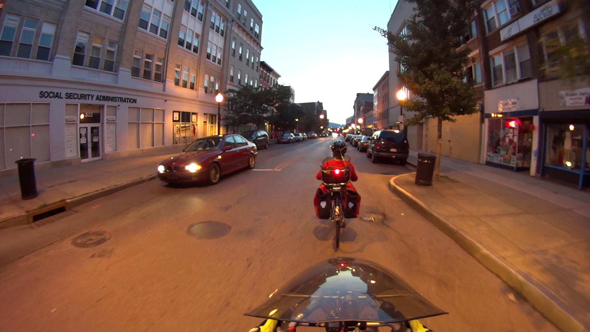
The Sony HDR-AS30V camera takes surprisingly good pictures in low light conditions, at least if you’re not too fussy about details like license plates…
At dusk, on our way to the City of Poughkeepsie’s Independence Day fireworks show:
Night Ride 2015-07-04 – AS30V – 0
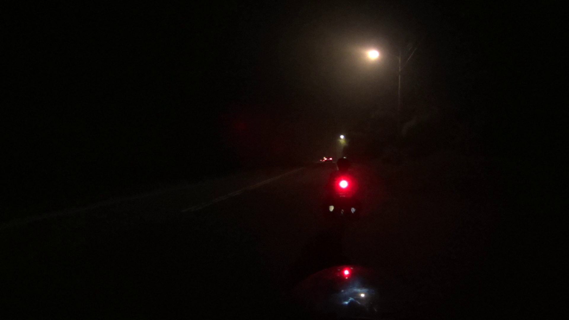
Returning in full dark:
Night Ride 2015-07-04 – AS30V – 1
A light fog set in as we got out of the city:
Night Ride 2015-07-04 – AS30V – 2
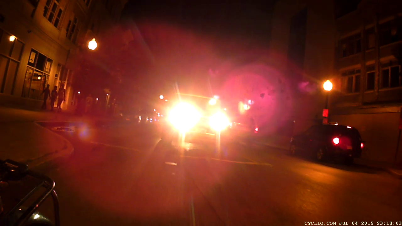
The Cycliq Fly6 faces a major challenge from in-its-face headlights, even with some background streetlighting:
Night Ride 2015-07-04 – Fly6 – 1
In full dark, it’s enough for mood-setting:
Night Ride 2015-07-04 – Fly6 – 2
That ride marks the annual exception to our general Don’t Bike After Dark rule. We set our blinky taillights to the legally required steady mode, although I think a low-power blink mode would be more conspicuous. Perhaps an occulting light (constant bright with dim pulses) would be better, but I’m not sure that’s legal.
A roadie on a fancy bike, riding dark without lights and reflectors, passed us. Watching him dodge a car that entered an intersection without seeing him once again demonstrated that cyclists are, in general, their own worst enemy.
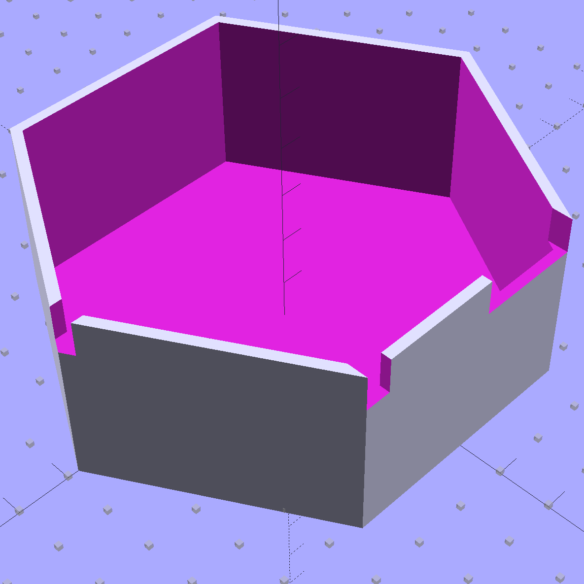
Although I’d thought of a Mu-metal shield, copper foil tape should be easier and safer to shape into a simple shield. The general idea is to line the interior with copper tape, solder the joints together, cover with Kapton tape to reduce the likelihood of shorts, then stick it in place with some connector pin-and-socket combinations. Putting the tape on the outside would be much easier, but that would surround the circuitry with a layer of plastic that probably carries enough charge to throw things off.
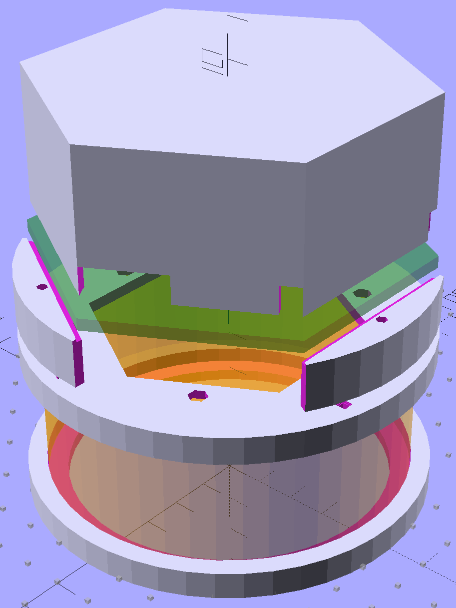
Anyhow, the hexagonal circuit board model now sports a hexagonal cap to support the shield:
Victoreen 710-104 Ionization Chamber Fittings – Show with shield
The ad-hoc openings fit various switches, wires, & twiddlepots:
At this instant, neither of us realized the other was present:
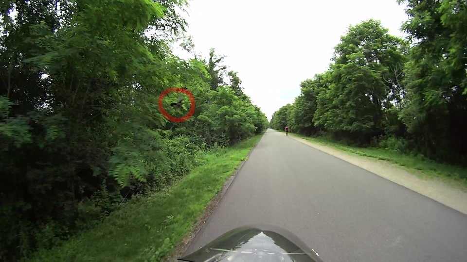
Starling-0145
Despite what it looks like, the blackbird (maybe a starling) passed just beyond arm’s reach directly ahead of the bike at eye level:
Starling-0167
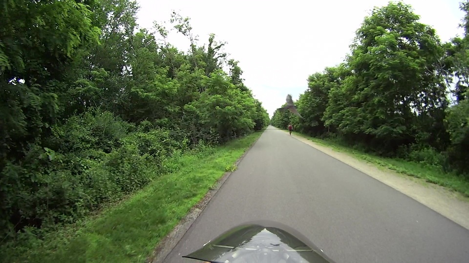
And away!
Starling-0173
At 60 frames per second, that’s 466 ms of elapsed time.
Stepping through the video, frame by frame, the bird’s wings flap at a consistent three frames per stroke = 50 ms/stroke = 20 stroke/s = 1200 stroke/min. A bit of rummaging produces a study suggesting a starling’s normal rate is 10 stroke/s, so the critter had the throttles firewalled at war emergency power.
It makes my pedal pushing seem downright inconsequential…
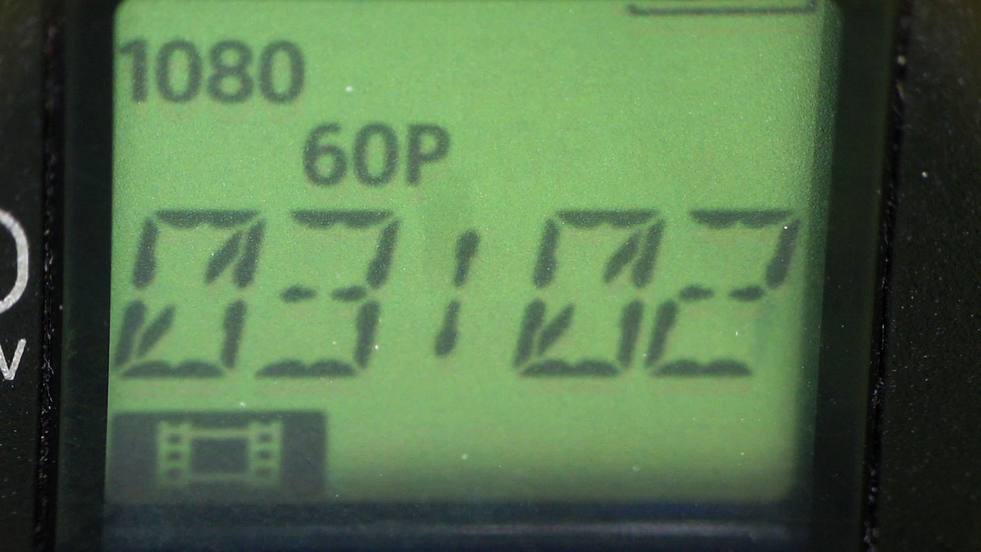
After about 1 TB of data spread over three months and maybe 100 bike rides, the second Sony SR-64UY 64 GB MicroSDXC card I bought last summer has failed… barely two weeks inside the one year warranty.
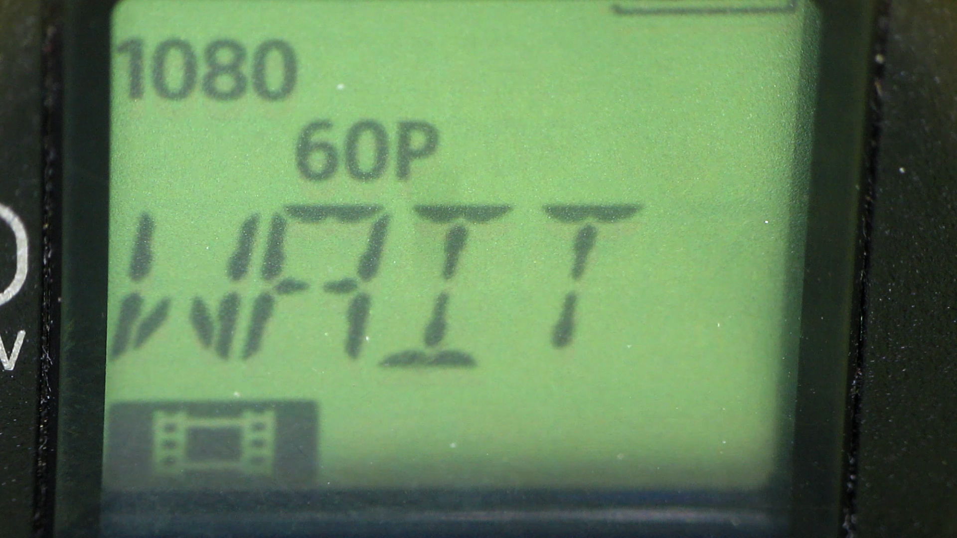
As with the first card, this one works fine except for the speed: it cannot record at 1920x1080p @ 60 fps. The only indication comes from aiming another camera at the display to capture the failure as it happens.
Just before the failure:
HDR-AS30V – MicroSDXC failure – 1
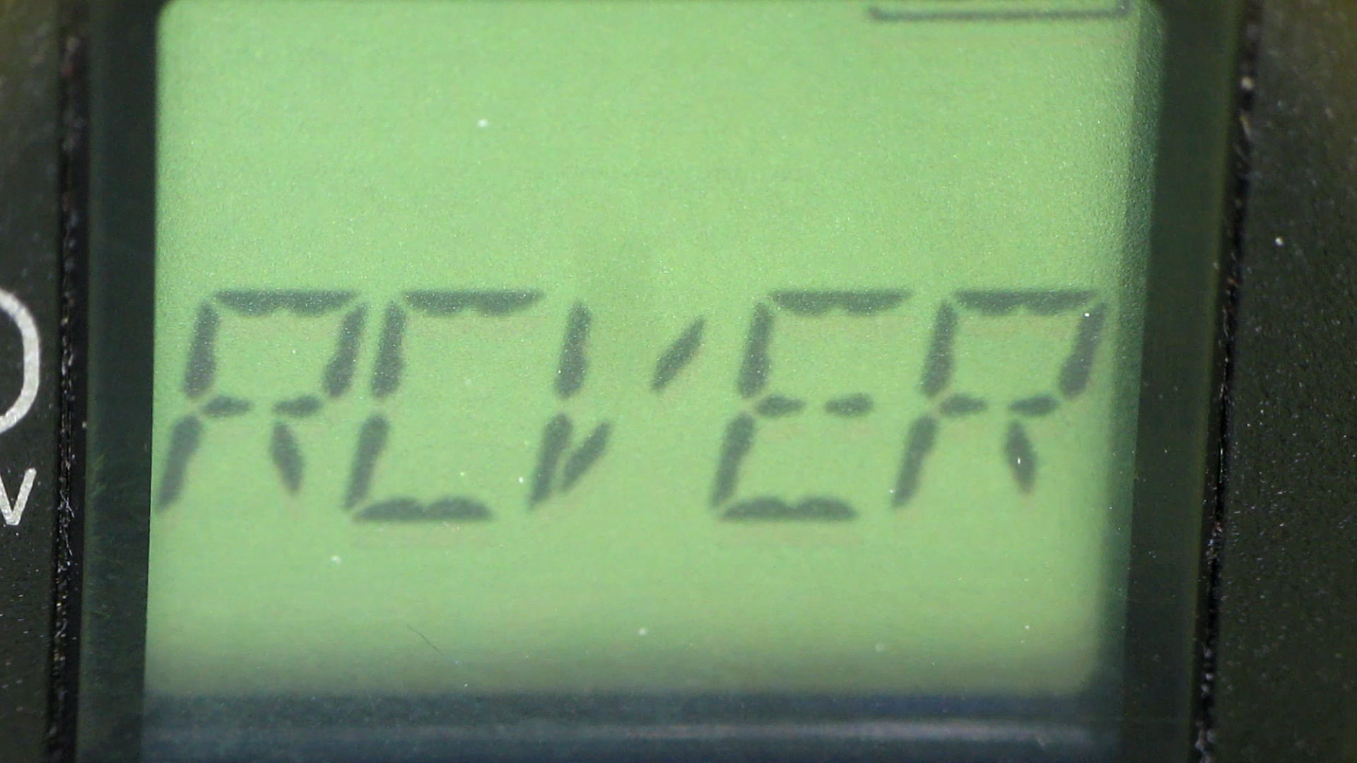
It’s taking stock of the situation:
HDR-AS30V – MicroSDXC failure – 2
Presumably, it’s patching up the abruptly terminated file:
HDR-AS30V – MicroSDXC failure – 3
Another box is on its way to Sony Media Services…
Over the last year, the price of an almost certainly genuine Sony SR-64UY Class 10 UHS-1 MicroSDXC card has dropped by 2.2 dB: $40 to $24. Now, however, the SR-64UY is the “old model”, so you can pay $30 (-1.3 dB) for an SR-64UY2 rated at 70 MB/s transfer speed (up from 40 MB/s), albeit with no change in the card’s speed class.
Huh.
Both cards failed after writing 1 TB of data (give or take maybe 20%) in 4 GB chunks over the course of 100 recording sessions. The cards still work, in the sense that they can store and accurately retrieve data, just not at the Class 4 (not Class 10) speed rating required by the HDR-AS30V at 1920x1080p @ 60 fps.
The table in the Wikipedia Secure Digital article says Class 4 = 4 MB/s, which is slightly faster than the camera produces 4 GB files in 22:43 min:sec = 3 MB/s. A Class 10 card should write at a sustained 10 MB/s, so the SR-64UY write speed has dropped by at least a factor of 3 from the spec. I’d expect the root problem to be the error correction / block remapping / spare pool handling time has grown as the number of failed blocks eats into the card’s overcapacity, but I have no inside information.
When the replacements slow down, I’ll see how they work as Raspberry Pi memory…